

Page 1
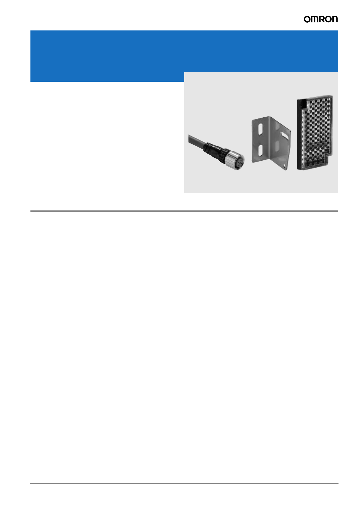
Sensor connectors, reflectors, mounting brackets, accessories
XS, Y92E, E39
The sensor accessory portfolio provides the products required to
connect, mount or operate the main photoelectric and inductive sensors. The accessories are designed to match the performance levels
of the respective sensors from general applications to the most challenging enviroments.
• Reflectors for standard applications, special mounting requirements
or special environments
• M8, M12 cable connectors
• Special fiber and photomicrosensor connectors
• Mounting brackets for square and cylindrical sensor shapes
Content
Cable connectors – quick guide and selection table . . . . . . . . . . . . . . . . . . . . . . . . . . . . . . . . . . . 2
Mounting accessories for standard photoelectric, inductive and capacitive sensors . . . . . . . . . . 24
Reflectors for retro-reflective photoelectric sensors . . . . . . . . . . . . . . . . . . . . . . . . . . . . . . . . . . . 34
1
Page 2

Cable connectors – quick guide and selection table
Size Shape Type Features
M8
M12
General
purpose
(screw)
Detergent
resistant
Robotic 4 pin Brass (CuZn)
General
purpose
(screw)
Detergent
resistant
105°C
Heat
resistant
3 pin (LED
optionally)
4pin
4 pin
3 wire (LED
optionally)
4 wire
5 wire
4 wire
4 wire
Material Order code
Nut Cable
Brass (CuZn)
Stainless
steel
(SUS316L)
Brass (CuZn)
Stainless
steel
(SUS316L)
Stainless
steel
(SUS316L)
PVC 2 m
PUR 2 m
PVC 2 m
PUR 2 m
PVC 2 m
Robotic
PVC 2 m
PVC 2 m
PUR 2 m
PVC 2 m
PUR 2 m
PVC 2 m
PUR 2 m
PVC 2 m
Heat resistant PVC
2m
Extended
Portfo lio
and Specs
on Page
XS3F-M8PVC3S2M
XS3F-M8PUR3S2M
XS3F-M8PVC4S2M
XS3F-M8PUR4S2M
Y92ES08PVC4S2M-L
XS3F-M421-402-R XS3F-M422-402-R 8
XS2F-M12PVC3S2M
XS2F-M12PUR3S2M
XS2F-M12PVC4S2M
XS2F-M12PUR4S2M
XS2F-M12PVC5S2M
XS2F-M12PUR5S2M
Y92ES12PVC4S2M-L
XS2F-E421-D80-E XS2F-E422-D80-E 12
XS3F-M8PVC3A2M
XS3F-M8PUR3A2M
XS3F-M8PVC4A2M
XS3F-M8PUR4A2M
Y92ES08PVC4A2M-L
XS2F-M12PVC3A2M
XS2F-M12PUR3A2M
XS2F-M12PVC4A2M
XS2F-M12PUR4A2M
XS2F-M12PVC5A2M
XS2F-M12PUR5A2M
Y92ES12PVC4A2M-L
3
3
6
3
3
3
6
Fiber
amplifier (E3X)
connector
Photomicrosensor
(EE-SX)
connector Cable
connector
M8/M12
Twist & click 4 wire
Robotic 4 wire Brass (CuZn)
Special
fiber
connector 4 wire
Fiber
amplifier
connectors
Cable
connector
Confection-
able
Special
fiber
connector +
M8 plug
Special
fiber
connector +
M12 plug
standard
cable
robotic
cable
Plugs and
connectors
for self
assembly
Nickel plated
Zinc
PBT PVC 2 m
Plug: Zinc
diecast
Nylon PVC 1 m
Brass n.a.
PVC 2 m
PUR 2 m
Robotic
PVC 2 m
PVC 30 cm
with M8
4-pin plug
PVC 30 cm
with M12
4-pin plug
XS5F-D421-D80-A
XS5F-D421-D80-P
XS2F-D421-D80-R XS2F-D422-D80-R 8
E3X-CN21 19
E3X-CN21-M3J-2 0.3M 19
E3X-CN21-M1J 0.3M 19
EE-1017 1M 21
EE-1017-R 1M 21
XS2G, XS2C
Y92E_conf
XS5F-D422-D80-A
XS5F-D422-D80-P
14
15
M12
M8/M12
2
Field I/0
boxes
T-connectors,
covers,
accessories
and extended
wiring
portfolio
Direct
wiring or
DeviceNet
communication
n.a. -
-
XW3B, DRT2 18
XS2R, XS3R, XY2F, .. 23
Page 3
General purpose connectors (M8/M12)
XS3F, XS2F
Ordering information
Type Size
M8
M12
General purpose
M8
M12
Material
Nut Cable
PVC
Brass
(Nickel plated)
PUR
Features Shape
angled
3 pin
straight
angled
4 pin
straight
angled
3 wire
straight
angled
4 wire
straight
angled
5 wire
straight
angled
3 pin
straight
angled
4 pin
straight
angled
3 wire
straight
angled
4 wire
straight
angled
5 wire
straight
Length
(m)
2 XS3F-M8PVC3A2M
5 XS3F-M8PVC3A5M
2 XS3F-M8PVC3S2M
5 XS3F-M8PVC3S5M
2 XS3F-M8PVC4A2M
5 XS3F-M8PVC4A5M
2 XS3F-M8PVC4S2M
5 XS3F-M8PVC4S5M
2 XS2F-M12PVC3A2M
5 XS2F-M12PVC3A5M
2 XS2F-M12PVC3S2M
5 XS2F-M12PVC3S5M
2 XS2F-M12PVC4A2M
5 XS2F-M12PVC4A5M
2 XS2F-M12PVC4S2M
5 XS2F-M12PVC4S5M
2 XS2F-M12PVC5A2M
5 XS2F-M12PVC5A5M
2 XS2F-M12PVC5S2M
5 XS2F-M12PVC5S5M
2 XS3F-M8PUR3A2M
5 XS3F-M8PUR3A5M
2 XS3F-M8PUR3S2M
5 XS3F-M8PUR3S5M
2 XS3F-M8PUR4A2M
5 XS3F-M8PUR4A5M
2 XS3F-M8PUR4S2M
5 XS3F-M8PUR4S5M
2 XS2F-M12PUR3A2M
5 XS2F-M12PUR3A5M
2 XS2F-M12PUR3S2M
5 XS2F-M12PUR3S5M
2 XS2F-M12PUR4A2M
5 XS2F-M12PUR4A5M
2 XS2F-M12PUR4S2M
5 XS2F-M12PUR4S5M
2 XS2F-M12PUR5A2M
5 XS2F-M12PUR5A5M
2 XS2F-M12PUR5S2M
5 XS2F-M12PUR5S5M
Order code
Note: M12 2-wire models are available for AC and DC applications.
Contact your Omron representative
3
Page 4
Specifications
M8 M12
Rated current 1A 4A
Rated voltage 125 VDC 125 VDC, 250 VAC
Degree of protection IP67 (IEC 60529)
Ambient temperature
PUR
PVC -25°C to 70°C
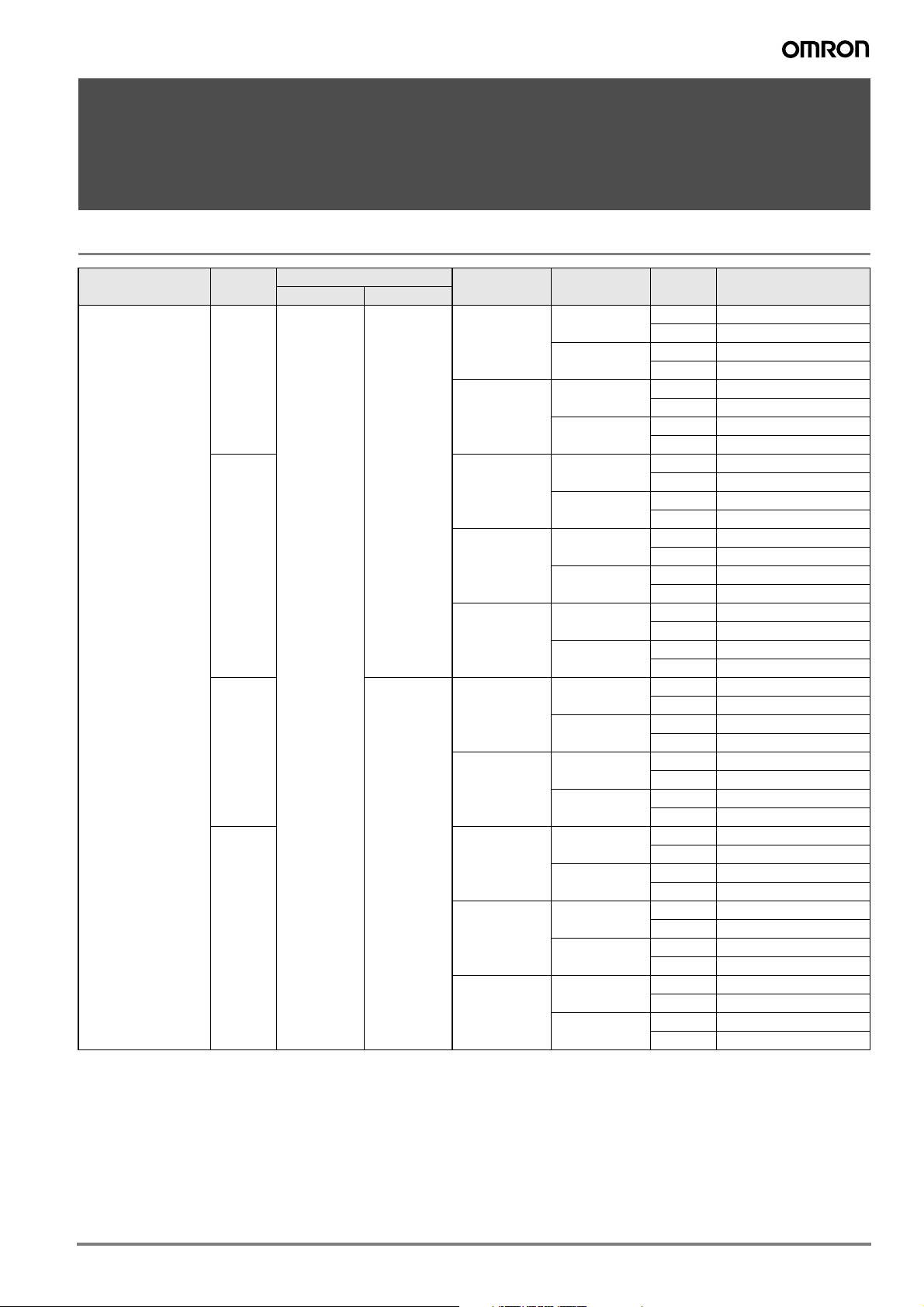
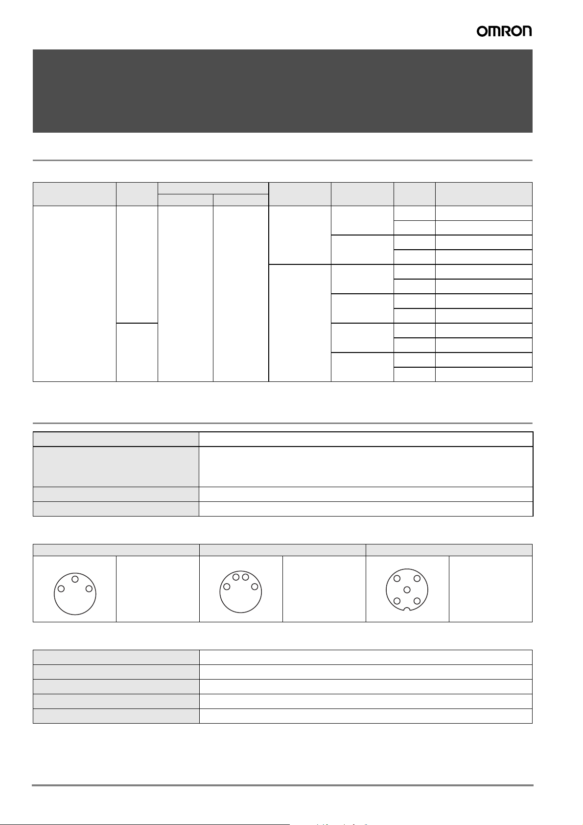
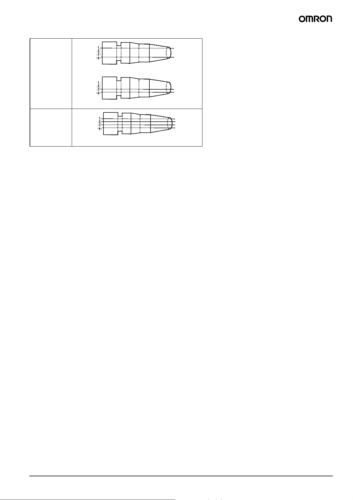
Pin arrangement
M8 3 poles M8 4 poles
4
31
M12 3 poles M12 4 poles M12 5 poles
34
1 = brown
2 = n.c.
21
3 = blue
4 = black
1 = brown
3 = blue
4 = black
Fixed cable: -50°C to 80°C
Moving cable: -25°C to 80°C
34
5
21
1 = brown
2 = white
3 = blue
4 = black
5 = n.c.
42
31
34
21
1 = brown
2 = white
3 = blue
4 = black
5
1 = brown
2 = white
3 = blue
4 = black
5 = green / yellow
Materials
Pin block PBT resin (UL 94V-0)
Contacts Brass/ nickel base, 0.4 µm gold plating
Fixture Brass/ nickel plated
Cover Polyester elastomer (UL 94V-O)
O-ring Rubber
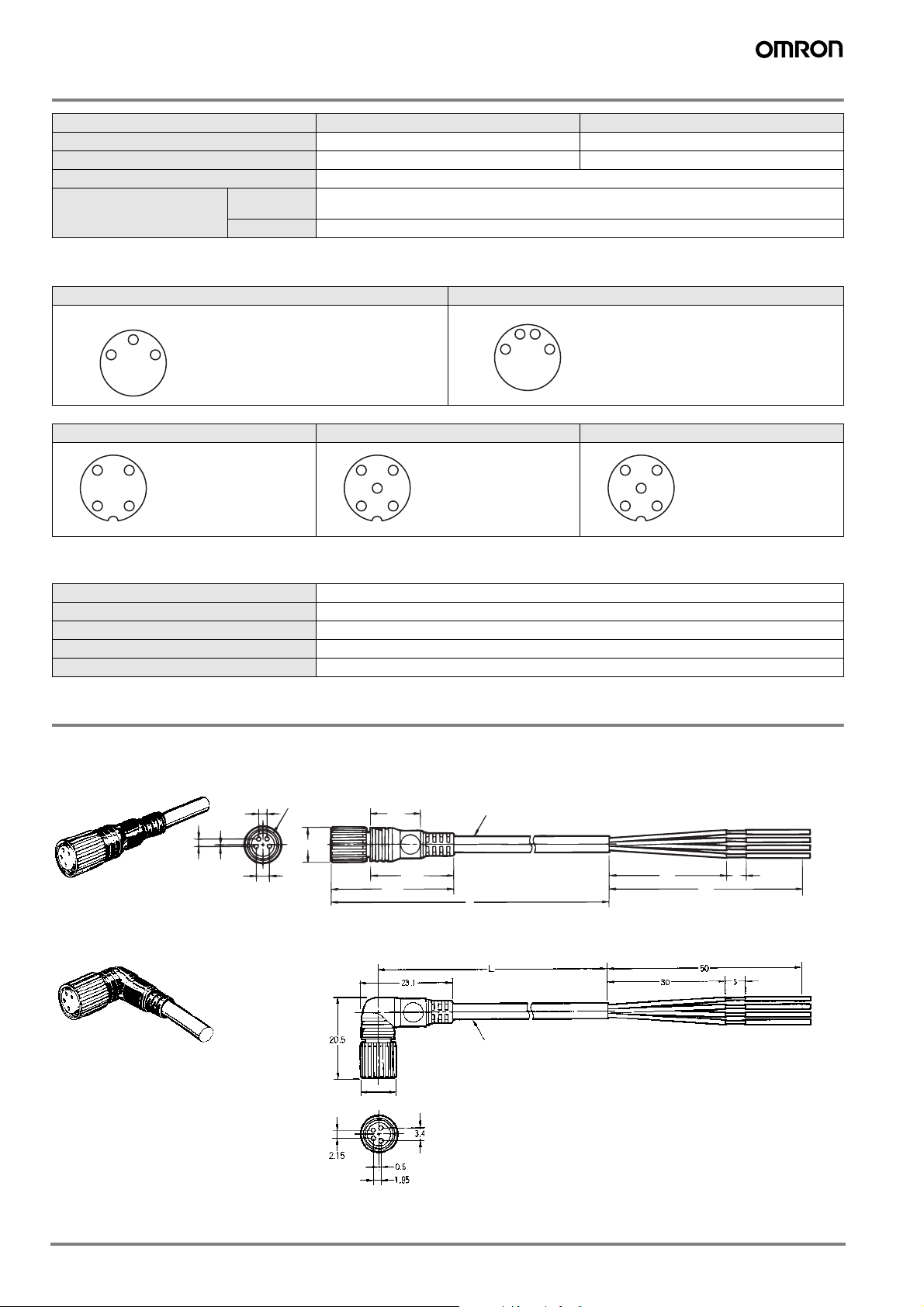
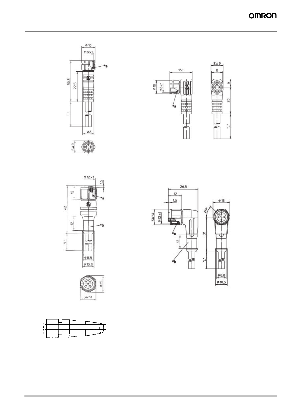
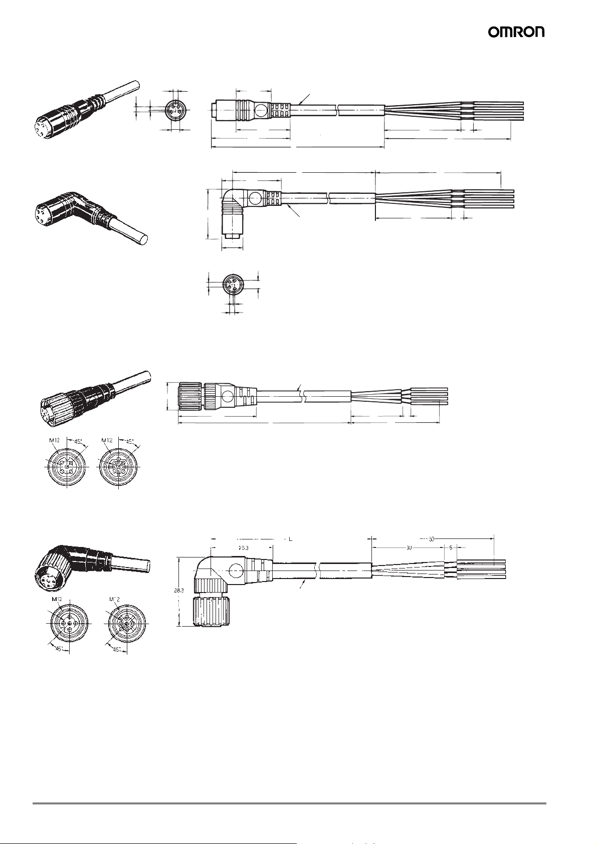
Dimensions
XS3F
M8 Screw-on cable connectors
Straight Connectors
M8
L-shaped Connectors
1.95 0.5
2.15
4
2
9 dia.
1
3
3.4
12.9
21.5
31.4
4 dia.
L
30
5
50
4 dia.
9 dia.
12
34
4
Page 5
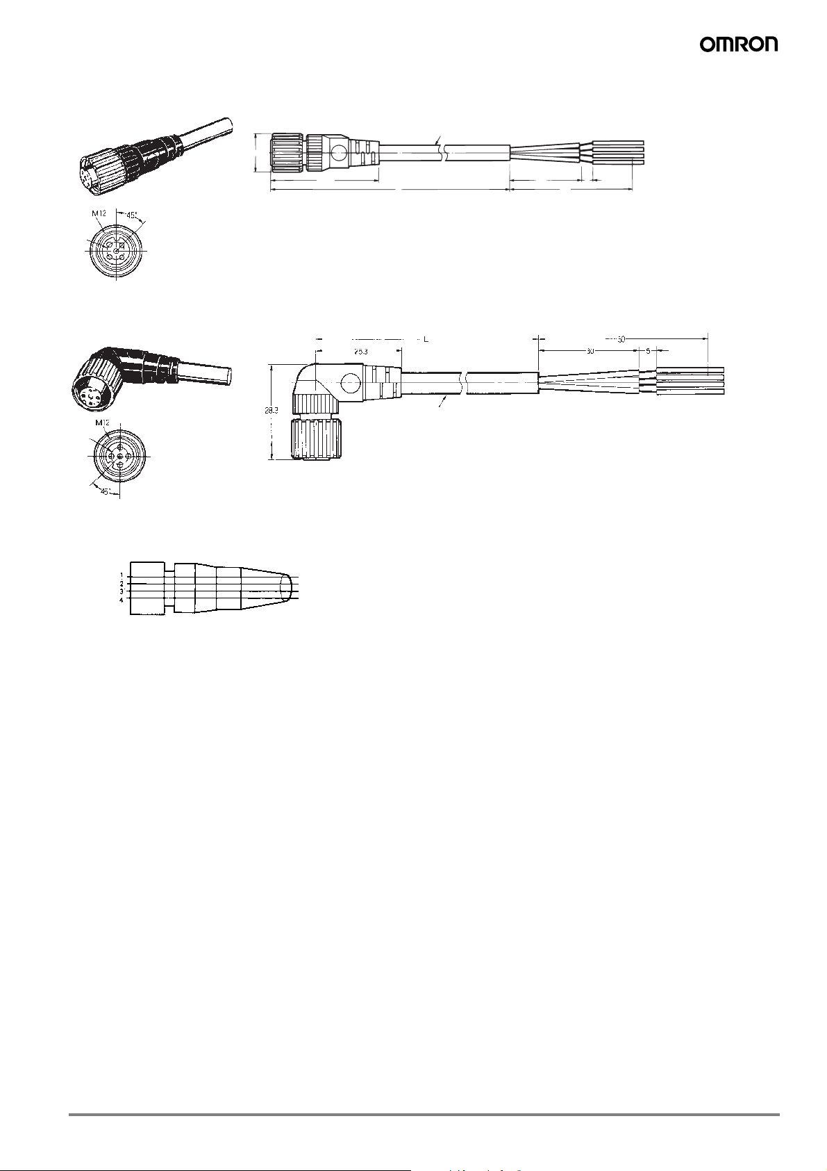
XS2F
DC
5 dia.
5 dia.
6 dia.
M12 Screw-on cable connectors
Straight Connectors
14.9 dia.
6 dia.
5 dia. 5 dia.
DC
L-shaped Connectors
Wiring Diagram (M8 and M12)
Contact No.
40.7 30
Brown
White
Blue
Black
Cable lead colors
L50
5
5
Page 6
Detergent resistant cable connectors (M8 / M12)
Y92E-S
Ordering information
Detergent resistant models
Typ e Size
M8
detergent resistant
M12
*1
For different cable length please contact your Omron representative
Material
Nut Cable
SUS 316L PVC
Specifications
Rated current
Rated voltage
Degree of protection
Ambient temperature
4A
M8 3 pin: 60 VDC
M8 4 pin: 30 VDC
M12 4-wire: 250 VDC
IP67 (IEC 60529); IP69k (after DIN 40050-1)
-25°C to +70°C
Features Shape
Angled
3 pin
Straight
Angled
Straight
4 pin
Angled
Straight
Length
*1
(m)
2 Y92E-S08PVC3A2M-L
5 Y92E-S08PVC3A5M-L
2 Y92E-S08PVC3S2M-L
5 Y92E-S08PVC3S5M-L
2 Y92E-S08PVC4A2M-L
5 Y92E-S08PVC4A5M-L
2 Y92E-S08PVC4S2M-L
5 Y92E-S08PVC4S5M-L
2 Y92E-S12PVC4A2M-L
5 Y92E-S12PVC4A5M-L
2 Y92E-S12PVC4C2M-L
5 Y92E-S12PVC4S5M-L
Order code
Pin arrangement
M8 3 pin M8 4 pin M12 4 pin
4
31
1 = brown
3 = blue
4 = black
42
31
1 = brown
2 = white
3 = blue
4 = black
34
21
Materials
Pin block
Contacts
Fixture
Cover
O-ring
PVC
CuSn, nickel base, 0.3 µm gold plating
Stainless steel
PVC
EPDM
6
1 = brown
2 = white
5
3 = blue
4 = black
5 = n.c.
Page 7
Dimensions
Y92E-S08
Y92E-S12
Wiring Diagram (M8 and M12)
Contact No.
Brown
White
Blue
Black
Cable lead colors
7
Page 8
Robot Cable Connectors (M8/M12)
XS3F-_-R, XS2F-_-R
Ordering Information
Typ e Size
Vibration-proof robot
cable (screw on)
M8
Vibration-proof robot
cable (snap on)
Vibration-proof robot
cable (screw on)
M12 Brass (CuZn) PVC
Vibration proof robot
cable (srew on) for AC
usage
Material
Nut Cable
Brass (CuZn) PVC 4 pin
Thermoplastic PVC 4 pin
Features Shape
2 wire
4 wire XS2F-D421-D80-R
2 wire
4 wire XS2F-D421-G80-R
2 wire
4 wire XS2F-D422-D80-R
2 wire
4 wire XS2F-D422-G80-R
2 wire
4 wire XS2F-A421-D90-R
2 wire
4 wire XS2F-A421-G90-R
2 wire Angled
Straight
Angled
Straight
Angled
Straight
Angled
Straight
Length
(m)
2 XS3F-M421-402-R
5 XS3F-M421-405-R
2 XS3F-M422-402-R
5 XS3F-M422-405-R
2 XS3F-S421-402-R
5 XS3F-S421-405-R
2 XS3F-S422-402-R
5 XS3F-S422-405-R
2
5
2
5
2
5
2 XS2F-A422-DB0-R
5 XS2F-A422-GB0-R
Order code
XS2F-D421-DA0-R
XS2F-D421-GA0-R
XS2F-D422-DA0-R
XS2F-D422-GA0-R
XS2F-A421-DB0-R
XS2F-A421-GB0-R
8
Page 9
Specifications
M8 M12
Rated current 1 A 3 A
Rated voltage 125 VDC 125 VDC, 250 VAC
Degree of protection IP67 (IEC529) IP67 (IEC529)
Ambient temperature Operating: -25C to 70C Operating: -25C to 70C
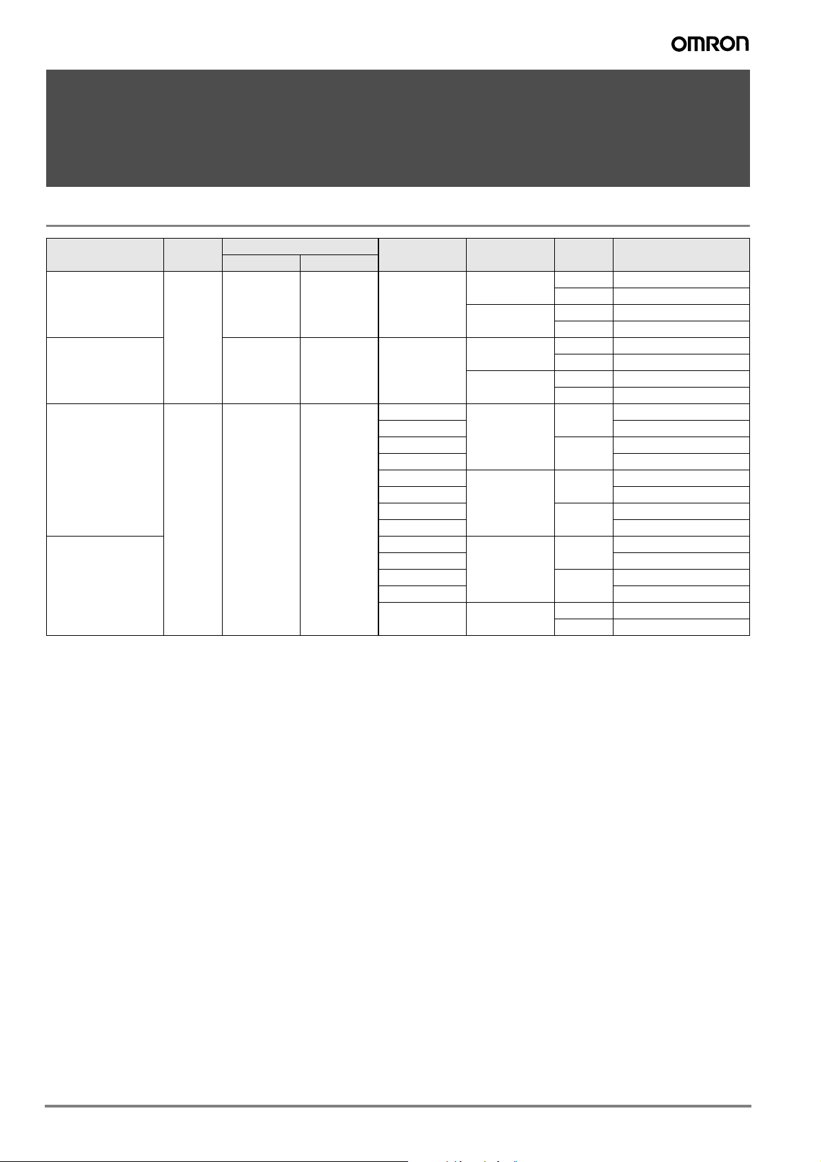
Pin arrangement
M8 M12
DC type AC type
Socket
Materials
M8 M12
Pin Block PBT resin/light gray or black PBT resin (UL94V-0), light grey or dark grey
Contacts Brass/nickel base, 0.4-m gold plating
Fixture Brass/nickel plated
Cover Thermoplastic elastomer/black Polyester elastomer
O-ring Rubber
Phosphor bronze, nickel base, 0.4-m gold
plating
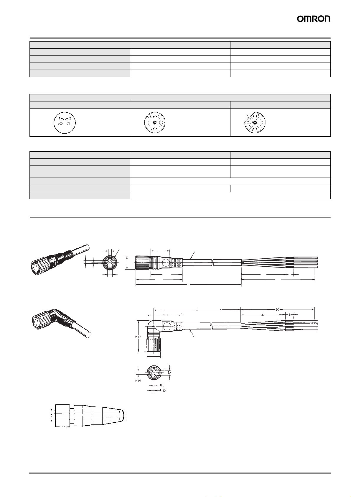
Dimensions
XS3F-_-R
M8 Screw-on cable connectors
Straight Connectors
1.95 0.5
Angled Connectors
M8
2.15
4
2
9 dia.
1
3
3.4
12.9
21.5
31.4
9 dia.
12
34
L
4 dia.
4 dia.
30
5
50
Wiring Diagram (M8)
Contact No.
Brown
White
Blue
Black
Cable lead colors
9
Page 10
M8 Snap-on cable connectors
Straight Connectors
Angled Connectors
4 dia.
4 dia.
2.15
2
1
4
3
3.4
0. 5
1.95
L
30.7
21.1
13.9
50
5
30
2.15
3.4
0.5
1.95
8.2 dia.
19.8
1
3
2
4
23.1
L5 0
5
30
DC AC
5 dia. 5 dia.
14.9 dia.
6 dia.
L50
5
40.7 30
Straight Connectors
XS2F-_-R
M12 Screw-on cable connectors
Angled Connectors
5 dia.
DC AC
10
5 dia.
6 dia.
Page 11
Wiring Diagram (M12)
2-wire model
4-wire model
Contact
No.
Contact
No.
Contact
No.
Brown
Blue
(DC)
Brown
Blue
(AC)
(DC/AC)
Brown
White
Bl
ue
Black
11
Page 12

Heat & chemical resistant cable connectors
XS2F-_-E
Ordering information
Typ e Size
Heat and detergent
resistant
M12 SUS316L
Material
Nut Cable
Heat resistant
PVC
Features Shape
4 pin
Specifications
Rated current 3A
Rated voltage 125 VDC, 250 VAC
Degree of protection IP67 (IEC 60529); IP69k (DIN 40050 part 9)
Ambient temperature -25°C to 105°C
Pin arrangement
M12 4 pin
34
5
21
Materials
1 = brown
2 = white
3 = blue
4 = black
5 = n.c.
straight
angled
Length
(m)
2 XS2F-E421-D80-E
5 XS2F-E421-G80-E
2 XS2F-E422-D80-E
5 XS2F-E422-G80-E
Order code
Pin block PBT (UL94V-0), light gray
Contacts Phosphor bronze, nickel base, 0.4 µm gold plating
Fixture SUS316L
Cover TPEE (UL94V-0), black
O-ring Rubber
12
Page 13

Dimensions
40.7
ø 6
M12
Color: Black
50
+20
–10
5±330±5
Straight knurl mO. 1
TWIST TIE
25.3
Color: Black
ø 6
28.3
Straight knurl
30±5
50
+20
–10
5±3
TWIST TIE
M12
Wiring Diagram (M12)
Contact No.
Brown
White
Blue
Black
Cable lead colors
13
Page 14

Twist & click (M12)
XS5F
Ordering information
Typ e Size
Twist & Click M12 Brass PVC
Note: The XS5F connectors can be attached to standard M12 plug connectors (screw-fix) and to XS5 plug connectors (twist & click). For details on the twist & click
locking mechanism refer to XS5 data sheet.
Material
Nut Cable
Features Shape
For standard
4 pin or Omron
Smartclick connectors
Angled
Straight
Length
(m)
2 XS5F-D422-D80-A
5 XS5F-D422-G80-A
2 XS5F-D421-D80-A
5 XS5F-D421-G80-A
Order code
Specifications
Rated current 4A
Rated voltage 125 VDC, 250 VAC
Degree of protection IP67 (IEC 60529)
Ambient temperature -25°C to 70°C
Pin arrangement Materials
M12 4 poles
34
5
21
1 = brown
2 = white
3 = blue
4 = black
5 = n.c.
Pin block PBT resin (UL94V-0)
Contacts Phosphor bronze/nickel base, 0.4 µm gold plating
Fixture Zinc alloy/nickel plated
Cover Polyester elastomer (UL94V-0)
O-ring Rubber
Dimensions
14.9 dia.
M12
40.7
L (Cable length)
6 dia.
305
50
14
Page 15

Confectionable plugs and connectors (self-assembly)
XS2C, XS2G, Y92E-_-conf
Ordering information
Type Size Material Nut Features Shape Order code
Plug (male)
Connector (female)
M8
M12
M8
M12
Polyester
elastomer
3 pin
4 pin Y92E-MM08PVC4Sconf-L
crimp
4 pin
5 pin screw fix
4 pin twist &
click
(for 4-5mm
cables)
3 pin
4 pin Y92E-M08PVC4Sconf-L
4 pin
5 pin screw fix
solder XS2G-D423
solder angled XS2G-D424
screw fix
crimp
solder XS2C-D423
crimp
solder XS2C-D424
straight
straight
straight XS2G-D5S1
angled XS2G-D5S2
straight XS2G-D4S3
angled XS2G-D4S4
straight
straight
angled
straight XS2C-D5S1
angled XS2C-D5S2
Y92E-MM08PVC3Sconf-L
XS2G-D4C3
Y92E-M08PVC3Sconf-L
XS2C-D4C3
XS2C-D4C4
Specifications
Y92E XS2G, XS2C
Rated current 4A
Rated voltage 36 VDC 125 VDC, 250 VAC
Degree of protection IP67 (IEC60529)
Ambient temperature -25°C to 70°C
Pin arrangement
M8 M12
Plug Connectors Plug Connectors
4 pin 4 pin 4 pin 5 pin 4 pin 5 pin
24
13
Materials
Pin block PVC PBT resin (UL94V-0)
Contacts
Fixture Brass/nickel base
Cover PVC PBT resin (UL94V-0)
O-ring FKM Rubber
42
31
4 pin: 1 = brown
2 = white
3 = blue
4 = black
5 = n.c.
Y92E XS2G, XS2C
CuSn, nickel base, 0.3 µm gold plating
4 3
12
4 3
5
12
Brass/nickel base, 0.4 µm gold plating
34
5
21
5 pin: 1 = brown
2 = white
3 = blue
4 = black
5 = green / yellow
15
Page 16

Dimensions
Plugs (male)
XS2G-D4C@ (Crimping Model, Straight),
XS2G-D42@ (Soldering Model, Straight)
45°
5 dia.
M12
DC
XS2G-D5S1 (Screw-on model, Straight)
XS2G-D42@ (Soldering Model, L-shaped)
45°
DC
XS2G-D5S2 (Screw-on model, angled)
5 dia.
M12 ´ 1
14.9 dia.
M12 ´ 1
14.9 dia.
20 dia.
M12 ´ 1
14.9 dia.
14.2 dia.
47.1
58.7
14 dia.
35.7
23
39.7
Connectors (female)
XS2C-D4C@ (Crimping Model, Straight),
XS2C-D42@ (Soldering Model, Straight)
DC
XS2C-D5S1 (Screw-on model, straight)
5 dia.
14.9 dia.
M12 ´ 1
20 dia.
14.9 dia.
39.6
14 dia.
14.2 dia.
54.9
20 dia.
14.9 dia. 14 dia.
16
Page 17

XS2C-D4C@ (Crimping Model, L-shaped)
XS2C-D42@ (Soldering Model, L-shaped)
5 dia.
DC
XS2C-D5S2 (Screw-on model, angled)
M12 ´ 1
14.9 dia.
20 dia.
35.9
14.9 dia.
39.6
14 dia.
17
Page 18

Field I/0 boxes
XW3B, XW3D, DRT2
Ordering information
Typ e Nr of inputs/ outputs
4 x M12 inputs
Direct wiring
Direct wiring with M12 Twist&click
DeviceNet
*1
NPN types are available on request
*2
For details refer to Omron XS5 product information
*3
Separate power supply. Models with power supply via DeviceNet cable are available
6 x M12 inputs XW3B-P653-G11
8 x M12 inputs XW3B-P853-G11
4 x M12 with smartclick inputs
8 x M12 with smartclick inputs
4 x M12 inputs
8 x M12 inputs
16 x M12 inputs
8 x M12 inputs + 8 x M12 outputs DRT2-MD16CL-1
Output
configuration
*1
PNP
*1
PNP
*1
PNP
Connection Order code
5m pre-wired
5m pre-wired
M12
(M12 DeviceNet cables
are available)
Specifications
XW3B/XW3D DRT2
Rated current
Rated voltage 10 to 30 VDC 24 VDC
Degree of protection IP67 (IEC 60529)
Operating temperature -25°C to 70°C -10°C to 55°C
4 A/port (signal lines)
12 A/box (power lines)
6 mA input
0.5 A per point (output)
XW3B-P453-G11
XW3D-P453-G11
XW3D-P853-G11
DRT2-ID04CL-1
DRT2-ID08CL-1
DRT2-HD16CL-1
*2
*2
*3
*3
Note: For details and dimensions refer to separate datasheet or www.industrial.omron.eu
18
Page 19

Fiber amplifier connectors
E3X-CN
Ordering information
Type Size Features Order code
4 wire; 2 m PVC cable E3X-CN21
3 wire; 2 m PVC cable E3X-CN11
Fiber amplifier connector Special connector 17,8x10x15,1
*1
Slave connectors can be used to reduce wiring effort. The setup requires 1 master amplifier with the slave amplifiers directly mounted attached. The power supply
is then provided by the master amplifier via the clipped on slave connectors. For 4-wire masters use 2-wire slaves and for 3-wire masters 1-wire slaves.
2 wire slave cable; 2 m PVC
1 wire slave cable; 2 m PVC
M8 4-pin plug with 30 cm PVC cable E3X-CN21-M3J-2 0.3M
M12 4-pin plug with 30 cm PVC cable E3X-CN21-M1J 0.3M
E3X-CN22
E3X-CN12
Specifications
Rated current 2.5 A
Rated voltage 50V
Degree of protection IP50 (EC 60529)
Groups of 1 or 2 amplifiers: -25 to 55°C
Ambient temperature
Groups of 3 to 10 amplifiers: -25 to 50°C
Groups of 11 to 16 amplifiers: -25 to 45°C
*1
*1
Materials
Housing Polybuthylene terephthalate (PBT)
Contacts Phosphor bronze/ gold plated/ nickel
Pin arrangement
42
31
M8
3 4
M12
21
Connector Cable colour
1brown+
2 orange/white
3blue–
4
black
pink Ext. Input
Output 2 or
ext. input
Output 1
19
Page 20

Dimensions
Master connectors
E3X-CN21/E3X-CN11
2.9
+50
10
6
2.6
14.4
6.8
10.7
4
2,000
*
0
4 dia.
*1
Only E3X-CN21
Slave connectors
E3X-CN22/E3X-CN12
*2
Only E3X-CN22
2.9
6
0.8
* E3X-CN21: 4-dia. vinyl-insulated round cable with 4 conductors (Conductor cross section: 0.2 mm2, Insulator diameter: 1.1 mm)
10
6
2.6
14.4
6
8
0.
* E3X-CN21: 4-dia. vinyl-insulated round cable with 4 conductors (Conductor cross section: 0.2 mm2, Insulator diameter: 1.1 mm)
8.4
6.8
8.4
15.1
10.7
15.1
2
30
+50
50
0
+50
2,000
0
4
*
4 dia.
2
30
+50
50
0
*1
2
10
*2
2
10
20
Page 21

Photomicrosensor connectors
EE-1
Ordering information
Type Size Features Applicable sensors Ordercode
Pin connector for soldering 13x4x10.8
13x4x13.5
Cable connector
10x5.8x8
Cable connector for EE-SX91
pigtail versions
10x5.8x8 robotic cable EE-SX91 EE-1016-R
Specifications
Rated voltage 5 to 24 VDC
Degree of protection IP50 (IEC 60529)
Ambient temperature range
operating: -25 to 55°C
storage: -30 to 80°C
For dark on
For light on EE-1001-1
standard cable EE-1010 2M
robotic cable EE-1010-R 2M
standard cable
robotic cable EE-1017-R 1M
EE-SX47/67
EE-SX97
EE-1001
EE-1017 1M
Material
EE-1001 EE-1010/EE-1016 EE-1017
Housing Nylon
Contacts Phosphor bronze
Cable – PVC 2 m
PVC 1 m
(3 m are available on request)
Pin arrangement
EE-1001, EE-1010 EE-1016 EE-1017
1 +Brown+Brown+Brown
2 L Pink output 2 White 1 Black
3 out Black – Blue 2 White
4 – Blue output 1 Black – Blue
Note: For the connector EE-1001-1 the pins 1(+) and 2 (L) are short circuited
21
Page 22

Dimensions
3.9
±
0.4
2.8
±
0.1
0.6
10.8
6
5
1.5
0.8
13
4
1.4
3
7.62
2.54
5.5
±
0.4
2
10
5.8
8 10 7162,000
1
2
3
4
Robot cable of 2.8 dia., 4 cores,
(0.15 mm
2
with 0.8-mm dia.insulator);
Standard length: 2 m
1
2
3
4
Connector with Cable: EE-1017
Vinyl insulated round cord: 4 dia., 4 cores,
(Cross section area of conductor: 0.2 mm
2
/ insulator: 1.1 mm dia.)
Connector with Robot Cable: EE-1017-R
Robot instrumentation cord: 4 dia., 4 cores,
(Cross section area of conductor: 0.2 mm
2
/ insulator: 1.1 mm dia.)
2
10
5.8 8
20
±5
1,000
+50
0
25
±5
15
±5
(8)
Connector with Robot Cable
EE-1017-R
Connector
EE-1001
13
±
0.15
2.54
4
0.6
10.8
6
±
1
2.9
Connector
(short-circuited between positive (+) and L terminals)
EE-1001-1
Connector with Cable
EE-1010
Connector with Robot Cable
EE-1010-R
EE-1010 cable
EE-1010-R cable:
Vinyl-insulated round
cable of 4 dia., 4 cores,
2
(0.2 mm
with 1.1-dia.
insulator)
13
7.62
2.54
4
0.6
2.5
3 24 1
1.4
Two, C1
5
13.5
±
5
20
2000
±
5
25
Connector with Robot Cable
EE-1016-R
±
5
15
22
Page 23

T-connectors, Covers, Accessories, extended wiring portfolio
XS2
Name Model Appearance
XS2W Plug connectors (Connector end)
Cable connectors with plugs
(open end or connector end)
XS2H Plug connectors (Open end)
XS2F Crimp Tool (for Crimping Connectors)
Connector Assembly Accessories (Crimping, Soldering, or
Screw-on)
Panel-mounting Connectors
T-Joints and Y-Joints
Used for branching and for
daisy-chain connections.
XS2U Crimping pin (for XS2G/XS2C)
XW4Z Screwdriver (for Screw-on Connectors)
XS2P Sockets (M12)
XS3P Sockets (M8)
Flange-mounting Plugs
XS2M Plugs (M12)
XS3M Plugs (M8)
Screw-mounting Plugs
T-Joints
XS2R T-Joint/Y-Joint Plug/Socket
Connectors (M12)
XS3R Y-Joint Plug/Socket Connectors
(M8)
Y-Joints
Dust covers
Used to protect unused
connector ports
Note: For details on these products, contact your Omron representative
XS2Z (M12)
XS3Z (M8)
Connector plugs
Connector covers
23
Page 24

Mounting accessories for standard photoelectric, inductive and capacitive sensors
E39, Y92E
Mounting brackets and covers
For cylindrical shapes
Shape
Product
group
Typ e Housing material Features Applicable sensors Order code
Mounting
brackets
general purpose screw fix
general purpose snap fix
general purpose screw fix
quick access snap fix
quick access clamp fix
plastic
stainless steel
plastic
stainless steel
- cost efficient mounting
bracket
- for M8, M12, M18, M30
- surface mounting
- for dia 20 mm -E3FZ (snap mount) E39-EL8
-for M18
- for dia 34 mm -E2K-C Y92E-A34
- snap fix for quick
sensor access
- for M8, M12, M18, M30
- surface mounting
- clamp fix for quick
sensor access with
exact repositioning
- for M8, M12, M18, M30
- through mounting
-E3F2
-E2A
-E3FZ (mounting with
M18 nuts)
-E3F2
-E3F2
(metal housing)
-E2A
(metal housing)
Y92E-B8
Y92E-B12
Y92E-B18
Y92E-B30
E39-EL12
Y92E-BC8
Y92E-BC12
Y92E-BC18
Y92E-BC30
Y92E-G8
Y92E-G12
Y92E-G18
Y92E-G30
24
Page 25

Shape
Product
group
Typ e Housing material Features Applicable sensors Order code
general purpose
sensor head
protection
sputter protection for
sensor head
general purpose lens
protection
Protective covers
polyarylate
silicone rubber
metal rim with glas
cover
- for M8, M12, M18, M30
- for shielded and
unshielded
- increased protection in
weld fields
- for M12, M18, M30
- for shielded sensors
For square shapes
Shape Typ e Housing material Features Mounting type
side wall mounting
Y92E-E8
Y92E-E12
Y92E-E18
Y92E-E30
-E2A
Y92E-E12-2
Y92E-E18-2
Y92E-E30-2
E3F2 E39-F31
Applicable
Sensors
Order code
E39-L43
General purpose
mounting
Stainless steel
(SUS 304)
inclination angle
adjustment
horizontal and
inclination angle
adjustment
up/down position
adjustment
back wall mounting E39-L44
surface mounting E39-L104
back wall mounting
surface mounting E39-L116
E3Z
E39-L117
E3T-S
25
Page 26

Shape Type Housing material Features Mounting type
Applicable
Sensors
Order code
General purpose
mounting
Stainless steel
(SUS 304)
up/down position
adjustment
inclination angle
adjustment
back wall mounting
E3T-F
side wall mounting E39-L120
back wall mounting
E3G-R
side and back wall
mounting
surface mounting E3G-L
E39-L119
E39-L132
E39-L131
-E39-L139
-E39-L140
26
Page 27

Shape Typ e Housing material Features Mounting type
Applicable
Sensors
E3G, E3Z E39-EL4
Order code
General purpose
mounting
Side protection
Stainless steel
(SUS 304)
3D rotation
inclination angle
adjustment
surface, side and
backwall mounting
protective side wall
mounting
E39-EL5
E3T, E3Z, E3C
E39-EL6
E3T-S E39-L118
27
Page 28

Shape Type Housing material Features Mounting type
Applicable
Sensors
Order code
Full protection
Stainless steel
(SUS 304)
inclination angle
adjustment
horizontal angle
adjustment
- 360° horizontal
rotation
- max telescope
length
protective side wall
mounting
protective surface
mounting
side and back wall
mounting
E39-L142
E3Z
(pre-wired types)
E39-L144
-E3Z E39-L98
-E39-L150
-E39-L151
-E3Z
-E39-R3
Telescope
mounting
3D rotation around
x, y, and z-axis
Extension pipe with
XY joint
Reflector adapter
for E39-L93_
side wall, back wall
and surface mounting
pipe mounting E39-L93_ E39-L93XY
telescope mounting
-E39-R1
-E39-R1S
E39-L93FH
E39-L93FV
E39-L96
28
Page 29

Slit, filters and other accessories
0.2
1
4.9
10.8
7.4
11.231.4
Shape Typ e Features Mounting type
Applicable
Sensors
Order code
E3Z-T E39-S65
Precision detection slit cover
Mutual interference prevention
Adjustment aid
- slit width from dia 0.5 mm for min object size detection of dia 0.2 mm
polarizing filter for close mounting
of multiple sensors through beam sensors
adjustment aid for sensitivity adjustment
snap on
E3T-@T
-E39-S63
-E39-S64
E3Z-T@A E39-E11
E3T-ST1 E39-E10
photo electric sensors with adjusta-
E39-G2
ble potentiometers
29
Page 30

Dimensions
E39-L43
E39-L44
E39-L87
Model
(typical)
A B
E3Z 188 59
E39-L93FH
1.2
30
3.5
Four, 3.2 dia.
R2
4.2
4.2
20°
0.1
±
R20
3.4
4.2
10
25
12.4
4.1
6.2 8.2
R2
13
1.5
7.5
R1
9.2
7.2
3.5
1.2
16.2
8.7
3.5
R3.5
9
6
18
6
R1
3.4
8
14
R1
26.3
20.9
E3Z
12 dia.
A
7
25.4
40
15
3.4
6
5
10
41
25.4
215
25.4
183
0.1
±
20°
R25.4
R2
23.2
1.2
3.2 dia.
36
3.2
31.2
48
15°
15°
4.2
75.6
43.7
2.6
15
54
6
30
35
50
26
48
B
Two,
6.6 dia.
22.5
45
30
Page 31

E39-L93FV
26.3
Model
(typical)
A B
E3Z 181 53
Note: The E39-L93XY consists of only the
one joint holder (A) and pipe (B), and
the two hexagonal bolts and nuts. It
cannot be mounted to the Sensor
alone.
E39-L93XY
Model
(typical)
A B
E3Z 170 40
E39-L96
E39-L98 (Vertical)
20.9
197
165
48
22
8
208
176
38
11
189
23
15
Holder (A)
B
12 dia.
A
Pipe (B)
12 dia.
20.9
26.3
E3Z
15˚
15˚
8
24
48
213
8
48
24
12
53
29
E3Z
12 dia.
35
50
15°
15°
A
B
Two, 6.6 dia.
60
E39-R1
reflector
9.5
29.5
15.5
Center of
pole brace
34.5
Mounting holes
E3S-R
E39-L96
27
61
38.5
Two, M6
Two, R28
±0.2
44
Stainless steel
(SUS304)
8.2
Screw
(provided)
16
(A)*
56
* The Mounting Bracket can
also be attached to surface A.
Four, R3.3
(For E3Z)
48
2
30° 30°
Two, R22
4 6.5
25.4
8
56 dia.
(E3S-R)
20
16
25
24
34
31
Page 32

R1
R1
R1.7
R1.7
3.4
5.8
12.5
(13.7)
4.5
6
29
3.4
R20
14°
Two, 3.2 dia.
3.5
16
R3.5
37.8
(39)
3.2
R25.4
10°
R1.6
8.8
1.2
E39-L104
E39-L116
Nut Plate
E39-L117
E39-L119
E39-L120
E39-L131
Three,
M2
R1.5 max.
7
(Four, R2)
9
15
90°
3
1.2
20.5
31.2
(17.8)
11
9.5
4.1
7.5
4
1.6
(Two, R1.7)
(Two, R2)
5
10
Two, 3.4
(Two, R2)
2.2
(Two, R1.1)
(Two, R1.2)
2.4
Nut Plate
Three,
M2
3.4
11.2
4.2
1216
7
4.5
(Four, R2)
9
15
Two, R2(Two, R1.7)
3.1
3.1
(Two, R1.7)
14
8
3
20.5
(Two, R2)
1811.5
22.5
13.56
9
15
(23)
Four, M2 Tap processing
1.2
90°
10.5
15
R1
max.
90°
1.2
2.4
4
9
5
10
(11.2)
1.2
2.4
2.4
Two, 2.2
(Two, R1.1)
(5.4)
8
5
3.2
Four, M2 Tap processing
1216
Two, R3.2
15°
1.5
R25
65.5
±1°
90°
4.2
R34
7
5.5
6.4
2-R3.2
Four, R1
R25
4.2
Four, R2.1
Two,
4.2 dia.
8.5
3.2
2.4
2.4
11.5
23.5
8
23.5
±0.1
25
35.5
8
9
6.4
22
35
±0.1
25
45
32
Page 33

E39-L132
1.5
5
37
55
12
4.5
R12
14
°
5
4
7.8
4.5
7
4.5
15.3
25.4
1.5
15.8
22
7
8.7
14
14
Four, 3.4-dia. holes
E39-L142
E39-L144
Model (typical) A B C D E F
E3Z 84.5 47.5 16.3 10.9 10 37
Model L
E39-L150 100
E39-L151 200
E39-L150 (Vertical)
E39-L151 (Vertical)
E39-L150
90°
±1°
Two, R3.2
Two, R17
Two, 50°
6.4
5.5
22
11.5
6.4
Four, R1.6
23.5
15°
Two, R3.2
R34
25
14.2
Two, R2.2
10
±0.1
25
4.4
21
1.5
4.2 dia.
23
38.5
23.5
11.5
Four, R1.6
7.3
25.4
8.5
4
Two, R25.4
5°
3.5
AL
F max.
20
14
Two, 3.5
C
Polybutylene
D
terephthalate
5.5
4.5
Two, 3.5 dia.
E
B
Two, 6.5 dia.
21
Polybutylene
terephthalate
25.4
20
6.8
Stainless steel
(SUS304)
10 dia.
8
19
35
32
46
33
Page 34

Reflectors for retro-reflective photoelectric sensors
E39-R
Accessories
Shape Type
General
purpose
reflectors
Small size
Housing
material
ABS base
Acrylic
surface
Features Size in mm Applicable Sensor Order code
Surface screw mounting (diagonal holes)
Surface screw mounting (holes on one side
only)
Side screw mounting
or surface selfadhesive
40x60x7.5
35.4x42.3x8 E39-R9
51.4x60.3x8.5 E39-R42
Retro-reflective photoelectric sensors – without
41.8x22.5x11 E39-R3
23x13.7x4.9 E39-R4
M.S.R
Retro-reflective photoelec-
tric sensors – with
*1
M.S.R.
E39-R1S
Large size
*1
Mirror Surface Rejection (MSR) is realized by using polarization filters
Surface screw
mounting
100x100x9 E39-R8
84.5x84.5x8.7 E39-R40
34
Page 35

Shape Typ e
Housing
material
Features Size in mm Applicable Sensor Order code
High
precision
Simple
mounting
Snap
mounting
ABS base
Acrylic
surface
ABS base
Acrylic
surface
Microtripel for improved
performance with fine
beam sensors
Round shape with
centered mounting
hole for simple screw
mounting
Snap mounting for fast
installation
52x40x4.8
E39-R6
30x45 E39-R12
Recommended for fine
beam coaxial models
(E3C-LR, E3Z-LR, E3TSR4)
14x23x1 E39-R37-CA
12x24 E39-R13
Diameter: 84
Depth: 7.4
Diameter: 30
Diameter of snap
mount tool: 5
Photoelectric sensors with
and without M.S.R.
*1
Recommended for snap
mounting sensor E3FZ
E39-R7
E39-R49
Enhanced
detergent
PVC
resistance
Highest
detergent
resistance
Heat
resistant
Non-fogging
reflector
*1
Mirror Surface Rejection (MSR) is realized by using polarization filters
SUS316L
Borosilicat
Borosilicat
ABS
Acrylic
surface
40x60x7.5
E39-R50
Surface screw
mounting
IP69k after DIN 40050
part 9
20x60x6 E39-R51
Surface screw
mounting
Surface screw mounting
450°C heat resistance
Suitable for vacuum
environment
43x30x5 E39-R16
95x51x8 E39-R47
Recommended for harsh
environment sensors
Anti-fogging coating 40x60x7.5 E39-R1K
35
Page 36

Shape Type
Housing
material
Features Size in mm Applicable Sensor Order code
Special
polarizing
General
purpose tape
reflectors
ABS base
PMMA
surface
Acrylic
Special polarizing filter
to PET
Self adhesive
Pre cut
Self adhesive
Self cut/roll material
40x80x8.5 E3ZM-B E39-RP1
35x10x0.7
Photoelectric sensors with
and without M.S.R.
Optimised for
E3T-SR4
*1
E39-RS1
E39-RS1-CA
E39-RS2
40x35x0.7
Optimised for
E3T-SR4
E39-RS2-CA
E39-RS3
80x70x0.6
25 mm x 5 m
25 mm x 22.8 m
50 mm x 5 m
50 mm x 22.8 m
Optimised for
E3T-SR4
E39-RS3-CA
E39-RS25 5
m
E39-RS25
22.8 m
E39-RS50 5
m
E39-RS50
22.8 m
High
precision
tape
reflectors
*1
Mirror Surface Rejection (MSR) is realized by using polarization filters
Self adhesive
Pre cut
195x22
Recommended for fine
beam and laser sensors
(E3Z-LR, E3C, E3X)
E39-RS4
108x46 E39-RS5
36
Page 37

Dimensions
E39-R1S
E39-R1K *
34
40.3
5259.9
2.7
8
1.6
7.5
7
Two, 3.5 dia.
Material, reflective
surface: acrylic
Rear surface: ABS
*E39-R1 only
Coating on reflective surface
E39-R9
42.3
#30.9
15
25
35.4
8
3.5
5.5
8
(21)
4
Two, 3.6 dia.
Material, reflective surface: acrylic
Rear surface: ABS
E39-R42
4.5
84
7.4
or M3
9
100
100
92
92
E39-R3
29
4.5
6
R20
3.4
7
18.45
22.9
11
20
0.2
0.2
16
22.5
19.3
34
3834.8
2-M3
41.8
10.1
1.2
25.4
R25.4
3.4
10˚
1.2
2.6
Stainless steel
(SUS304)
Adhesive tape side
Two, 3.2 dia.
13.7
14˚
3.4
Material, reflective
surface: acrylic
Rear surface: ABS
E39-R4
13.7
9.7
2
4
23
19
Two, 2.2 dia.
1.4
4.9
4
2
Material:
Reflective surface:
acrylic
Rear surface: ABS
E39-R6
40
34
40
52
3.5
3.5
4.8
Material, reflective
surface: acrylic
Rear surface: ABS
E39-R37-CA
10.2
8.7
(1.1)
13.7
13.7
8-R1
18.323
18.3 23
2-R1.55
Mounting
bracket: t 0.5
Two, 3.1 dia.
Reflector: t0.6
(adhesive tape side)
Reflector
Mounting bracket
Material:
Mounting plate: stainless steel (SUS301)
Reflective surface: acrylic
Note: The reflective plate and mounting plate (1) come as a set.
72
63.680
44
Two , 3.5-dia.
Reflective surface
3
8.5
0.2
E39-RP1
E39-R7 E39-R40 E39-R8
7.4
4.5
84
8.7
for M3
84.5
77
77
84.5
ffor M3
9
100
92
92
100
E39-R12/-R14
45
37
30
E39-R13
24
17.2
12
37
Page 38

In the interest of product improvement, specifications are subject to change without notice.Cat. No. E26E-EN2-04
OMRON EUROPE B.V.
Wegalaan 67-69,
NL-2132 JD, Hoofddorp,
The Netherlands
Phone: +31 23 568 13 00
Fax: +31 23 568 13 88
www.eu.omron.com
38
 Loading...