

Page 1

Fluid level sensor (contact type)
E32-D82F
High-accuracy detection of
fluid level in washing tank.
● Uses Teflon (PFA) with excellent chemical and oil
resistance.
● Capable of detecting high-temperature fluids
such as sulfuric acid in a wafer washing tank.
(-40 to +200°C)
● Achieves a high repetition precision of 0.5 mm
(in pure water).
● Employs a dripping prevention mechanism.
Ordering Information
Fiber Units
Sensor type Shape Model Remarks
E32-D82F1
Diffuse-reflective
E32-D82F2
Length of no-bending section:
150 mm from tip
Length of no-bending section:
350 mm from tip
E32-D82F
Applicable amplifier unit
Model
E3X-DA-N
E3X-NA
Rating/performance
Sensor type Diffuse-reflective
Item Model E32-D82F1 E32-D82F2
Standard sensing object Pure water at 25°C
Differential distance 3 mm max.
Repetition precision 0.5 mm or less
Permissible angle of detection
object inclination
Perim-
Teflon section within
eter
1.5 m of fiber tip*1
Tem-
Parts other than the
pera-
above
ture
Ambient humidity Operating/storage: 35 to 85% RH
Peripheral pressure Operating: -50 kPa to 500 kPa
Admissible bending radius
(10% under fluid level)
average)
Material
Protective structure IEC Standard IP68*2
Weight (Packed state) Approx. 75 g
Accessories Fiber cutter
*1. Teflon is a registered trademark of Dupont Company and Mitsui Dupont Chemical Company for their
fluoride resin.
*2. Only applies to Teflon section; the standard requires no bubbling when air at 98 kPa is injected for 30 sec-
onds at a depth of 100 mm in water.
Length of nobending section
Sensor case Teflon (PFA)
Fiber cladding Black polyethylene
Connector Brass-nickel coating
±10° or less
Operating: -40 to +200°C, Storage: -40°C to +85°C
(with no icing or condensation)
Operating/storage: -40 to +85°C
(no ice formation or condensation)
40 mm or higher (25 mm for plastic fiber section)
150 mm from tip 350 mm from tip
Principle of operation
Air
Liquid
• In air, the difference between the index
of refraction of the Teflon section and
that of air is larger, and the light is
reflected by the detected surface and
returns to the light receiver.
• In the fluid, there is almost no difference
between the index of refraction of the
Teflon section and that of the fluid, and
the light radiates into the fluid.
A-361E32-D82F
Page 2
Operation
● Teaching type
1. Using teaching without work
Perform teaching with the tip of the fiber unit in the fluid. (The
sensitivity is set to the top 10% of the received light intensity in
fluid for stronger performance with respect to fluctuations in
received light intensity due to fluid leakage, and thus teaching
without work for high viscosity fluids is effective.)
2. Using teaching with/without work
Perform teaching after the object has been removed from the
fluid, and then repeat teaching with the object in the fluid.
(Teaching with/without work is effective for fluids in which
bubbles form at high temperature.)
Note: If set to the maximum sensitivity with the object removed from the fluid,
detection of the fluid will no longer be possible.
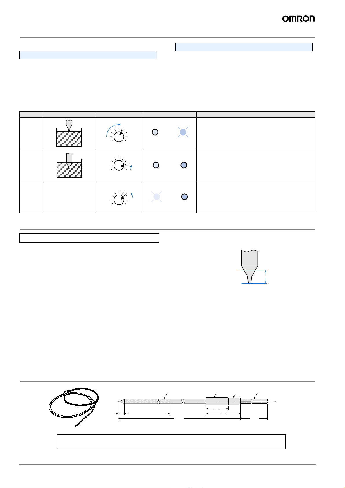
● Sensitivity control type
Sequence Detection state Sensitivity adjuster Indicator state Adjustment procedure
(A)
1
18
2
3
---
18
18
(B)
(A)
(C)
(B)
Green Red
OFF OFF
Green Red
OFF OFF
Green Red
ON OFF
Determine the position A at which the incident light indicator lamp
(red) illuminates as the sensitivity control is gradually increased
from the minimum setting after the object has been removed from
the fluid.
• If the red indicator lamp illuminates at the maximum sensitivity
setting, gradually decrease the sensitivity control from the
maximum setting with the object in the fluid, and determine the
position B at which the incident light indicator lamp (red) goes
off.
• If the red indicator lamp goes off at the maximum sensitivity
Set the sensitivity control to C midway between A and B. At this
time, verify that the stability indicator lamp (green) illuminates
both with and without fluid.
Precautions
Correct Use
Installation
• Use the no-bending section to secure the fiber unit. If the
fiber unit is secured without using the no-bending section,
the fluid level detection position may shift.
• Influences from the sides or bottom may interfere with
detection. In that case, remove to a distance that is not subject
to these influences, or apply a black coating to the sides and
bottom.
• If you need to use the system in a dangerous location, use only
the fiber unit in the dangerous location and place the amplifier
unit in a safe location.
Dimensions (Unit: mm)
E32-D82F1
E32-D82F2
Not bend, length: 150 (350) * 1
7.2
● For adjustment
About the fluid level detection position
The fluid level detection
position is located 5.2±2
mm from the tip of the
Teflon section (see the
diagram at right). The
Surface level detection position
±2
5.2
mm (From a Teflon part tip)
fluid level detection
position will vary depending on the surface tension of the fluid
and the dampness of the detection position of the fiber unit.
Miscellaneous
• Operation will not be stable in the following situations. A
Bubbles adhere to the cone of the detector head. B Solutes
have precipitated onto the cone of the detector head. C
The fluid has a high viscosity.
• Some fluids such as those of a milky-white color may not
permit detection.
• Take care not to strike the tip with any object. A damaged or
deformed detector head may cause unstable operation.
Sensing head 6 dia. (Teflon)
* 1. ( ): E32-D82F2 dimensions
* 2. Freely cut because 2m part of optical fiber at amplifier side is made from a plastic fiber.
2,000
Fiber connector 9dia.
(Nickel-plated brass)
27
42
8 dia.
Optical fiber two, 2.2 dia. * 2
2,000
To an amplifier side
ALL DIMENSIONS SHOWN ARE IN MILLIMETERS.
To convert millimeters into inches, multiply by 0.03937. To convert grams into ounces, multiply by 0.03527.
Cat. No. E41E-EN-01
In the interest of product improvement, specifications are subject to change without notice.
A-362 Advanced Photoelectric Sensors
 Loading...