

Page 1
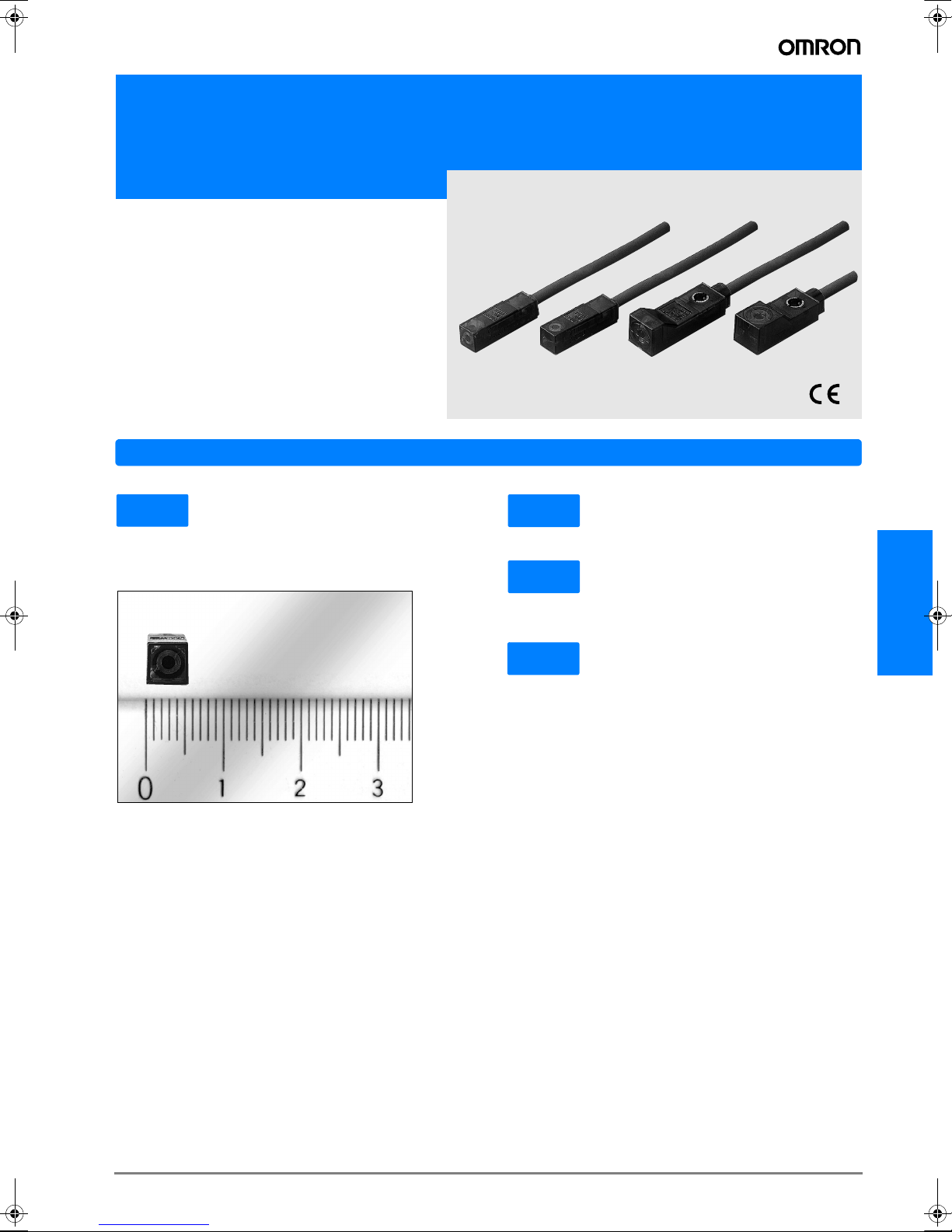
Miniature Square Inductive Proximity Sensor
E2S
• Miniature housing with long sensing ranges
• Front ans side facing sensing surfaces
Features
5.5 mm
The 5.5 mm x 5.5 mm type permits smaller, space-saving machines and devices.
Adopted for more compact machines and devices.
Ultra small housing
5.5mm
1 kHz
IP67
Full sealing structure housing, degree of protection IEC60529 IP67.
1/20
Significantly lower current consumption. The 0.8 mA (for 24
VDC) leakage current for the DC 2-wire type has a ratio of approximately 1/20 compared to the conventional DC 3-wire
type. Optimum solution for multiple-sensor applications such
as cam switches.
High-Speed Response
Environment-Resistant Types
Low Current Consumption (Compared to conventional models)
E2S
D-61E2S
Page 2
Ordering Information
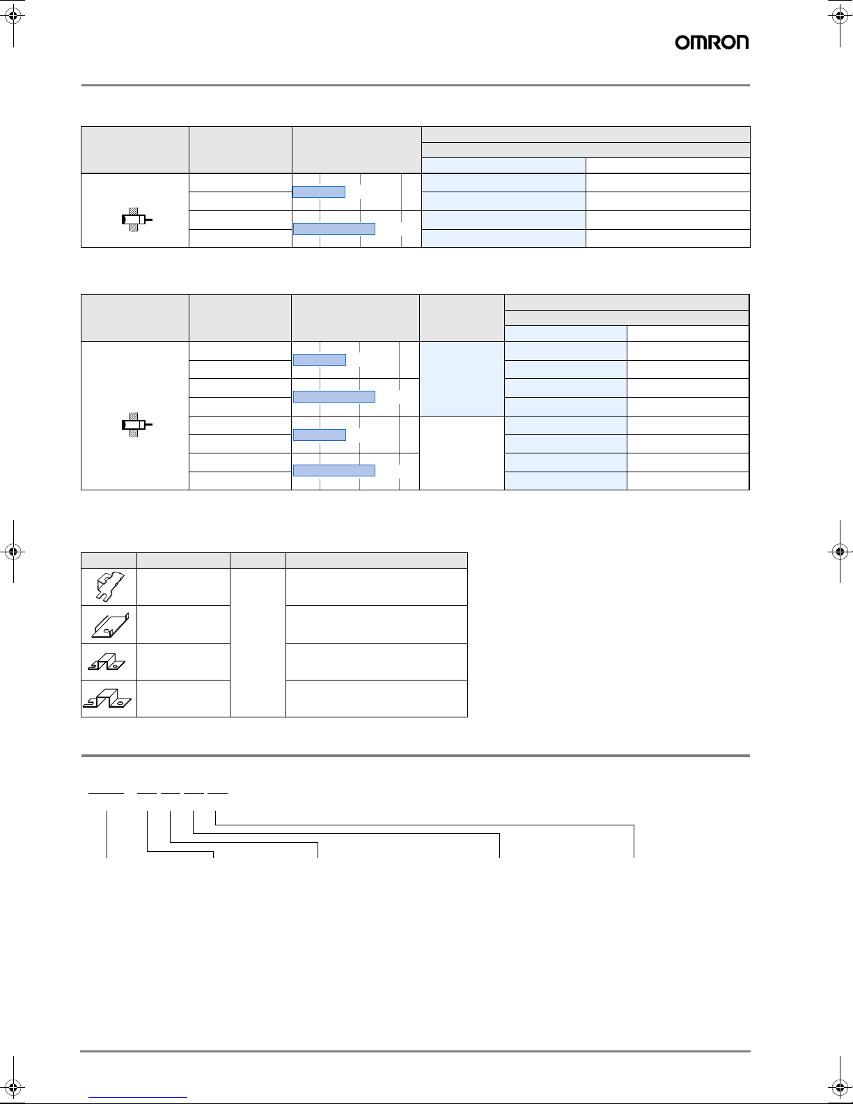
Sensors
DC 2-wire Models
Model
Shape Sensing surface Sensing distance
NO NC
Front face E2S-W11 * E2S-W12
Unshielded
* Models with different response frequency are available (NO only). These model numbers take the form E2S-###B (e.g., E2S-W11B)
End face
Front face
End face
1.6mm
2.5mm
E2S-Q11 * E2S-Q12
E2S-W21 * E2S-W22
E2S-Q21 * E2S-Q22
DC 3-wire Models
Shape Sensing surface Sensing distance
Front face
End face
Front face
Unshielded
* Models with different response frequency are available (NO only). These model numbers take the form E2S-###B (e.g., E2S-W11B)
End face
Front face
End face
Front face
End face
1.6mm
2.5mm
1.6mm
2.5mm
Output
specifications
NPN
PNP
Operating status
Model
Operating status
NO NC
E2S-W13* E2S-W14
E2S-Q13* E2S-Q14
E2S-W23* E2S-W24
E2S-Q23* E2S-Q24
E2S-W15* E2S-W16
E2S-Q15* E2S-Q16
E2S-W25* E2S-W26
E2S-Q25* E2S-Q26
Accessories (Order Separately)
Mounting Brackets
Shape Model Quantity Remarks
Y92E-C1R6
Y92E-C2R5
Y92E-D1R6 ---
Y92E-D2R5 ---
Provided with E2S-#1
Provided with E2S-#2
1
Nomenclature
E2S - ####
ABCDE
A Compact square
series
B Sensing direction
W: Front face sensing
Q: End face sensing
C Size and sensing distance
(standard sensing object)
1: 5.5 x 5.5 mm, 1.6 mm (iron)
2: 8 x 8 mm, 2.5 mm (iron)
##
##
D Output
1: DC 2-wire NO
2: DC 2-wire NC
3: DC 3-wire NPN NO
4: DC 3-wire NPN NC
5: DC 3-wire PNP NO
6: DC 3-wire PNP NC
E Different response
frequency
No: Standard
B: Different response
frequency
D-62 Inductive Sensors
Page 3
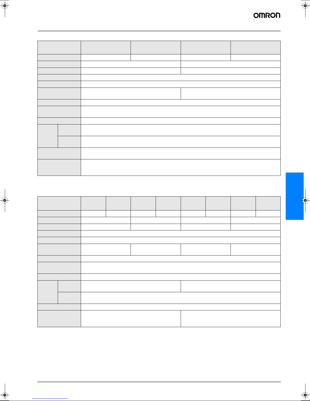
Rating/Performance
DC 2-wire Models
Model
Item
Sensing surface Front face End face Front face End face
Sensing distance 1.6 mm ±10% 2.5 mm ±15%
Setting distance
Differential distance 10% max.
Sensing object Ferrous metal (Sensitivity lowers with non-ferrous metals)
Standard sensing
object
Response frequency 1 kHz min.
Rated supply voltage
(operating voltage)
Leakage current
Switching
Control
output
Indicator lamp
Operating status
(with sensing object
approaching)
* The response frequencies for DC switching are average values measured under the condition that the distance between each sensing object is twice as large as the
size of the sensing object and the sensing distance set is half of the maximum sensing distance.
capacity
Residual
voltage
E2S-W11
E2S-W12
0 to 1.2 mm
Iron, 12 x 12 x 1 mm Iron, 15 x 15 x 1 mm
12 to 24 VDC (10 to 30 VDC), ripple (p-p): 10% max.
0.8 mA max.
3 to 50 mA DC max.
3 V max. (under load current of 50 mA with cable length of 1 m)
##1 models: Operation indicator(red LED), Operation set indicator(green LED)
##2 models: Operation indicator(red LED)
##1 models: NO
##2 models: NC
E2S-Q11
E2S-Q12
E2S-W21
E2S-W22
0 to 1.9 mm
E2S-Q21
E2S-Q22
DC 3-wire Models
Model
Item
Sensing surface Front face End face Front face End face Front face End face Front face End face
Sensing distance 1.6 mm ±10% 2.5 mm ±15% 1.6 mm ±10% 2.5 mm ±15%
Setting distance
Differential distance 10% max.
Sensing object Ferrous metal
Standard sensing
object
Response frequency 1 kHz min.
Rated supply voltage
(operating voltage)
Current consumption 13 mA max. (24 VDC, unload)
Switching
Control
output
Indicator lamp Operation indicator (orange)
Operating status
(with sensing object
approaching)
* The response frequencies for DC switching are average values measured under the condition that the distance between each sensing object is twice as large as the
size of the sensing object and the sensing distance set is half of the maximum sensing distance.
capacity
Residual
voltage
E2S-W13
E2S-W14
0 to 1.2 mm
Iron, 12 x 12 x 1 mm Iron, 15 x 15 x 1 mm Iron, 12 x 12 x 1 mm Iron, 15 x 15 x 1 mm
12 to 24 VDC (10 to 30 VDC), ripple (p-p): 10% max.
NPN open collector 100 mA max. (30 VDC max.) PNP open collector 50 mA max. (30 VDC max.)
1 V max. (under load current of 50 mA with cable length of 1 m)
##3 models: NO
##4 models: NC
E2S-Q13
E2S-Q14
E2S-W23
E2S-W24
0 to 1.9 mm 0 to 1.2 mm 0 to 1.9 mm
E2S-Q23
E2S-Q24
E2S-W15
E2S-W16
##5 models: NO
##6 models: NC
E2S-Q15
E2S-Q16
E2S-W25
E2S-W26
E2S-Q25
E2S-Q26
E2S
D-63E2S
Page 4

Specifications
Item Model E2S-###
Protective circuits Reverse polarity connection and surge absorber
Ambient temperature Operating: -25°C to 70°C, Storage: -40°C to 85°C (with no icing or condensation)
Ambient humidity Operating: 35% to 90%RH, Storage: 35% to 95%RH (with no condensation)
Temperature influence ±15% max. of sensing distance at 23°C in temperature range of -25°C to 70°C
Voltage influence ±2.5% max. of sensing distance within a range of ±10% of rated supply voltage
Insulation resistance 50 M min. (at 500 VDC) between energized parts and case
Dielectric strength 1,000 VAC for 1 min between energized parts and case
Vibration resistance 10 to 55 Hz, 1.5-mm double amplitude for 2 hours each in X, Y, and Z directions
Shock resistance Destruction: 500 m/s2 for 3 times each in X, Y, and Z directions
Protective structure IEC60529 IP67
Connection method Pre-wired models (Standard length: 3 m)
Weight (Packed state) Approx. 10 g
Material Case Polyarylate
Accessories Mounting Brackets
Characteristic data (typical)
Sensing Distance vs. Sensing Object
E2S-W1#/-Q1# E2S-W2#/-Q2#
2
1.5
Distance X (mm)
1
0.5
Iron
SUS
Brass
Copper
X
Aluminum
t=1mm
#d
4
#d
3
Distance X (mm)
2
1
t
mm
=1
X
X
Iron
SUS
Brass
Copper
Aluminum
01020304050
Side length of sensing object d (mm)
0 102030405060
Side length of sensing object d (mm)
D-64 Inductive Sensors
Page 5

Output Circuit Diagram
DC 2-wire Models
Operating
status
NO
NC
Model Timing chart Output circuit
E2S-W11
E2S-W21
E2S-Q11
E2S-Q21
E2S-W12
E2S-W22
E2S-Q12
E2S-Q22
Sensing
object
(%)
Sensing
object
(%)
Rated sensing
distance
Non-sensing
zone
Setting position
Unstable
Sensing
Stable sensing zoneNon-sensing zone
zone
100 080
Sensing zoneNon-sensing zone
100 0
Proximity Sensor
ON
Setting indicator (green)
OFF
ON
Operation indicator (red)
OFF
ON
Control output
OFF
Proximity Sensor
ON
Operation indicator (red)
OFF
ON
Control output
OFF
Main
circuit
Brown
Blue
Load
+V
0V
DC 3-wire Models
Operating
status
NO
NC
NO
NC
specifications
Output
NPN
PNP
Model Timing chart Output circuit
E2S-W13
E2S-W23
E2S-Q13
E2S-Q23
E2S-W14
E2S-W24
E2S-Q14
E2S-Q24
E2S-W15
E2S-W25
E2S-Q15
E2S-Q25
E2S-W16
E2S-W26
E2S-Q16
E2S-Q26
Sensing object
Output transistor (load)
Operation indicator (orange)
Sensing object
Output transistor (load)
Operation indicator (orange)
Sensing object
Output transistor (load)
Operation indicator (orange)
Sensing object
Output transistor (load)
Operation indicator (orange)
Yes
OFF
OFF
Yes
OFF
OFF
Yes
OFF
OFF
Yes
OFF
OFF
ON
ON
No
ON
ON
ON
ON
ON
ON
No
Main
circuit
* Maximum load current: 50 mA
No
Main
circuit
No
* Maximum load current: 50 mA
Brown
Black
Output
Blue
Brown
Black
Blue
E2S
+V
Load
*
0V
+V
*
Load
0V
D-65E2S
Page 6

Precautions
Correct Use
Design
Effects of Surrounding Metal
• Provide a minimum distance between the Sensor and the
surrounding metal as shown in the table below.
• Front Surface Sensing Type (Not exceeding the sensor
head height)
Sensing surface
A
Proximity Sensor
(Unit: mm)
Model Length A B C
E2S-W1#
E2S-W2# 15 10
0
• End Surface Sensing Type
A
C
(Unit: mm)
Model Length A B C
E2S-Q1# 832
E2S-Q2# 15 10 3
Sensing
B
surface
CC
Proximity Sensor
82
B
B
Mutual Interference
If more than one Sensor is located face to face or in parallel,
be sure to maintain enough space between adjacent Sensors
to suppress mutual interference as provided in the following
diagram,.
• Front Surface Sens-
• End Surface Sensing Type
ing Type
A
(Unit: mm)
Model Length A B
E2S-W(Q)1# 50 (40) 20 (5.5)
E2S-W1# 75 (50) 25 (8)
Note: The above values in parentheses are applicable when using two sensors
with different frequencies.
B
A
B
Mounting
Tightening torgues
Do not tighten the E2S-W(Q)2#mounting screws to a torque
exceeding 0.7 Nm.
D-66 Inductive Sensors
Page 7

Dimensions (Unit: mm)
Sensors
E2S-W1#
E2S-Q1#
5.9
8.4
2.9 dia. vinyl-insulated
round cable, 2 / 3 cores
(conductor sectional
2
area: 0.14mm
diameter: 0.9 dia.) ;
standard length: 1 m
, Insulator
E2S-W2#
2.9 dia. vinyl-insulated round
cable, 2 / 3 cores (conductor
sectional area: 0.14mm
Insulator diameter: 0.9 dia.)
; standard length: 1 m
2
,
3.1 dia. mounting holes
5.3
If mounting bracket is attached
2.6
R1.5
22
22.3
25.1
1
19
If mounting bracket is attached
Indicator *
11.3
20
10.1
11.5
15.5
Sensing surface
8
8
7.4
2
2
3.1 dia.
3
2.5
10.8
Sensing surface
6.4
5.5
Indicator *
* E2S-W11#
E2S-W12#
E2S-W13#
E2S-W14#
E2S-W15#
E2S-W16#
7.4
7.8
*E2S-W21#
E2S-W22#
E2S-W23#
E2S-W24#
E2S-W25#
E2S-W26#
2
2.3
5.9
Operation indicator (red)
Setting indicator (green)
Operation indicator (red)
Operation indicator (orange)
2.3
Operation indicator (red)
Setting indicator (green)
Operation indicator (red)
Operation indicator (orange)
If mounting bracket is attached
8.4
2.9 dia. vinyl-insulated
round cable, 2 / 3 cores
(conductor sectional area:
2
, Insulator diameter: 0.9 dia.) ;
0.14mm
standard length: 1 m
2
R1.5
1
E2S-Q2#
2.5
2.9 dia. vinyl-insulated round cable,
2 / 3 cores (conductor sectional area:
0.14m‡u, Insulator diameter: 0.9 dia.) ;
standard length: 1 m
5.3
3.1 dia.
3.1 dia. mounting holes
3
Indicator *
Sensing surface
6.4
5.55.9
2
22.3
25.1
19
* E2S-Q11#
E2S-Q12#
E2S-Q13#
E2S-Q14#
E2S-Q15#
E2S-Q16#
If mounting bracket is attached
3.6
2
2
Sensing surface
8
8.9
*E2S-Q21#
E2S-Q22#
E2S-Q23#
E2S-Q24#
E2S-Q25#
E2S-Q26#
8
8.4
10.8
11.3
23
2.5
Indicator *
14.5
4.1
18.5
2
2.3
5.9
Operation indicator (red)
Setting indicator (green)
Operation indicator (red)
Operation indicator (red)
2.3
Operation indicator (red)
Setting indicator (green)
Operation indicator (red)
Operation indicator (orange)
E2S
Accessories (Order Separately*)
Mounting Brackets
Y92E-C1R6
Material: Stainless
steel (SUS304)
* Provided with
E2S-
#1##
Mounting Brackets
Y92E-D1R6
Material: Stainless
steel (SUS304)
2.4
5.9
8.4
Two, R1.6
7
20.4
17.2
15
14
8
5.3
2
11.3
2.5
R1.2
R1.5
Two, R1.2
9.5
1.52.3
3
M3
3.2
1
5
3
R1.6
17.4
5.6
5.3
5
2
1.5
5.6
6.4
1.1
3.5
1.3
Mounting Holes
17.5
Four, R1
3.2
3
0.9
0.3
2
5.7
Two, R0.7
0.4
Mounting Holes
2.3
2.4 dia. screw
depth 2 min.
Two, M3
12
Mounting Brackets
Y92E-C2R5
Material: Stainless
steel (SUS304)
* Provided with
#2#
E2S-
Mounting Brackets
Y92E-D2R5
Material: Stainless
steel (SUS304)
7.8
Two, R1.6
2.5
3.1 dia.
10.8
11.3
2.5
0.4
8.1
2.3
0.4
2
2
Mounting Holes
11.5
Mounting Holes
Two, M3
dia. 2.4 screw
depth 3 min.
17
M3 screw depth 8 min.
22.4
1
16
3.2
3.2
8
7
R1.6
5
Four, R1
0.2
D-67E2S
Page 8

ALL DIMENSIONS SHOWN ARE IN MILLIMETERS.
To convert millimeters into inches, multiply by 0.03937. To convert grams into ounces, multiply by 0.03527.
Cat. No. E902-E2-02-X
In the interest of product improvement, specifications are subject to change without notice.
D-68 Inductive Sensors
 Loading...