

Page 1
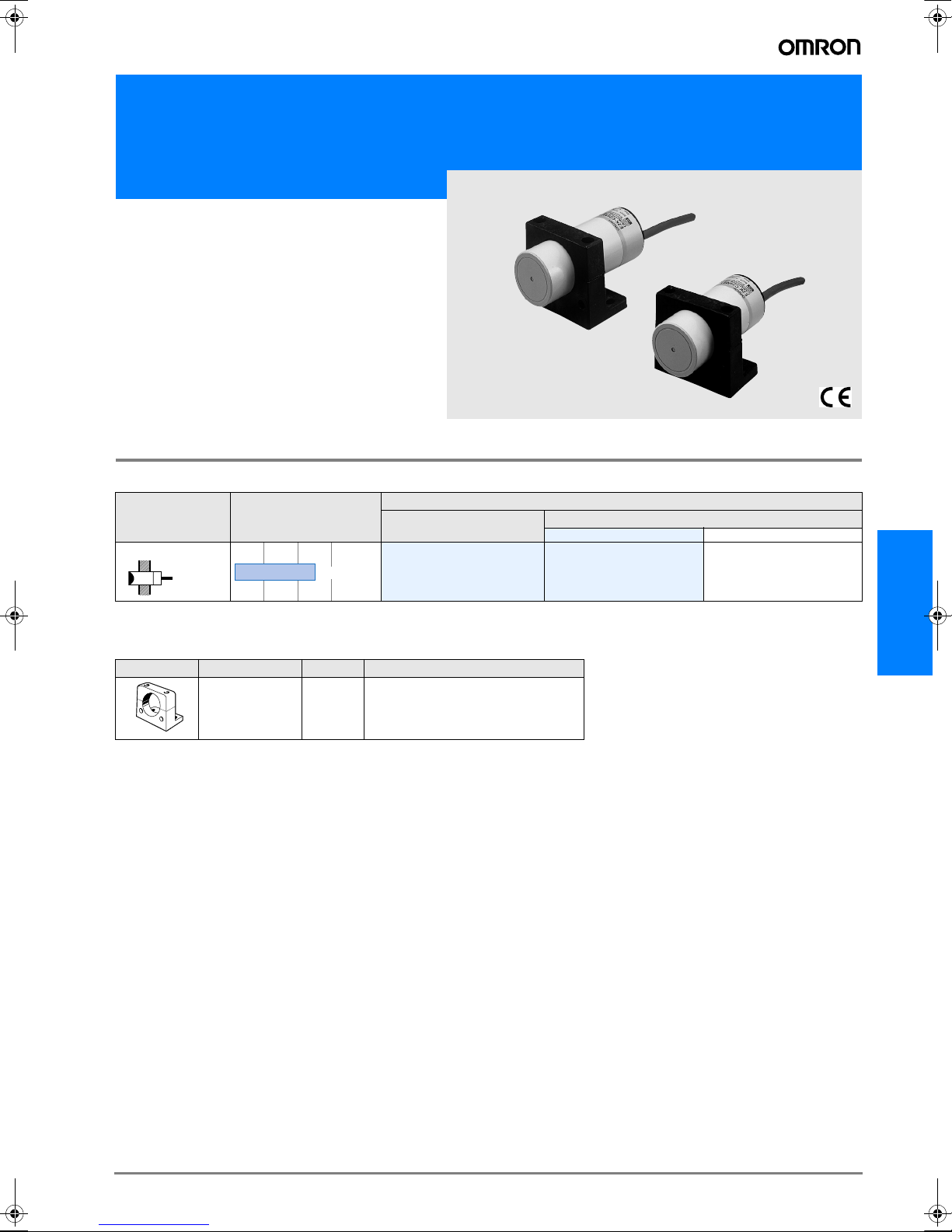
Long-distance Capacitive Proximity Sensor
E2K-C
Capacitive Proximity Sensor
with Adjustable Sensitivity
• Detects both metallic and non-metallic objects (glass,
lumber, water, oil, plastic, etc.) without direct contact.
• DC models acquire CE marking
Ordering Information
Sensors
Shape Sensing distance
Unshielded
34 dia.
3 to 25mm
Output specifications
DC 3-wire NPN
DC 3-wire PNP
Model
Operating status
NO NC
E2K-C25ME1
E2-KC25MF1
E2K-C25ME2
E2K-C25MF2
Accessories (Order Separately)
Mounting Brackets
Shape Model Quantity Remarks
Y92E-A34 1 Supplied with the product.
E2K-C
D-183E2K-C
Page 2
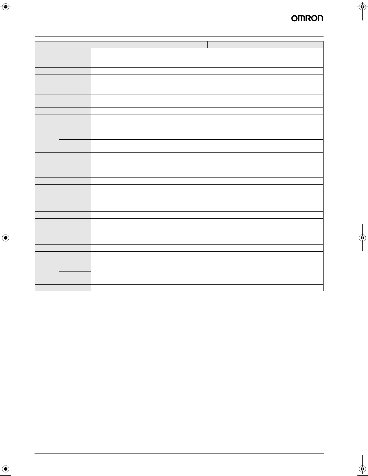
Rating/Performance
Item Model E2K-C25M#1 E2K-C25M#2
Sensing distance * 25 mm
Sensing distance
adjustable range
Sensing object Conductors and dielectrics
Standard sensing object with grounded metal: 50 x 50 x 1t mm
Differential distance 15% max. of sensing distance (when adjusted to 25 mm ±10% with standard object)
Response frequency
Power supply(Operating
voltage range)
Current consumption E models: 10 mA max. at 12 VDC, 16 mA max. at 24 VDC
Leakage current
Switching
Control
output
Indicator lamp Detection indicator (red LED)
Operating status
(with sensing object
approaching)
Protective circuits Reverse connection protection, surge absorber
Ambient temperature Operating/Storage: -25°C to 70°C (with no icing or condensation)
Ambient humidity Operating/Storage: 35% to 95%RH (with no condensation)
Temperature influence ±15%max. of sensing distance at 23° within temperature range -10°C to 55°C
Voltage influence ±2% max. of sensing distance at a voltage between 85% and 115% of the rated power supply voltage
Insulation resistance 50 M min. (at 500 VDC) between current carry parts and case
Dielectric strength
Vibration resistance 10 to 55 Hz, 1.5 mm double amplitude for 2 hours each in X, Y, and Z directions
Shock resistance Destruction: 500 m/s2 for 10 times each in X, Y, and Z directions
Protective structure IEC 60529 IP66
Connection method Pre-wired models (standard length: 2 m)
Weight (Packed state) Approx. 200 g
Material
Accessories Mounting bracket, instruction manual
* The set distances are sensing distances applicable to standard sensing objects. Refer to Engineering Data for sensing distances applicable to other types of objects.
capacity
Residual
voltage
Case
Sensing
surface
3 to 25 mm
70 Hz
12 to 24 VDC, ripple (p-p): 10% max.,(10 to 40 VDC)
Y models: 1 mA max. at 100 VAC (50/60 Hz) with output turned OFF., 2 mA max. at 200 VAC (50/60 Hz)
with output turned OFF.
200 mA max.
2 V max. (under load current of 200 mA with cable length of 2 m)
E1, Y1 models: NO
E2, Y2 models: NC
1000 VAC 50/60 Hz for 1 min
between energized part and case
Heat-resistant ABS resin
D-184 Capacitive Sensors
Page 3

Characteristic data (typical)
Sensing Distance Change by Sensing Object (Typical)
25
20
Sensing distance X (mm)
15
10
5
0
Salt
Flour
Sugar
500 ml milk
(pure water)
(50 x 50 x t1)
Standard sensing object
Phenol resin
(50 x 50 x 15)
(50 x 50 x 15)
Neoprene rubber
Glass
Lavan plate
(200 x 50 x t3)
(160 x 120 x t15)
(Duracon)
Resin pellet
Output Circuit Diagram
DC 3-wire Models
Operating
status
Model Timing chart Output circuit
NO E2K-C25ME1
NC E2K-C25ME2
NO E2K-C25MF1
NC E2K-C25MF2
Sensing object
Load
(between brown and black)
Output voltage
(between black and blue)
Operation indicator (red)
Sensing object
Load
(between brown and black)
Output voltage
(between black and blue)
Operation indicator (red)
Sensing object
Load
(between brown and black)
Output voltage
(between black and blue)
Operation indicator (red)
Sensing object
Load
(between brown and black)
Output voltage
(between black and blue)
Operation indicator (red)
Yes
No
Operates
Releases
H
L
ON
OFF
Yes
No
Operates
Releases
H
L
ON
OFF
Yes
No
Operates
Releases
H
L
ON
OFF
Yes
No
Operates
Releases
H
L
ON
OFF
Brown
Brown
Black
Output
Blue
Brack *1
Output *2
Blue
*2
*1
Load
Load
4.7kW
4.4kW
2.2W
100W
Main
circuit
* 1. 200 mA max. (load current)
* 2. When a transistor is connected
Main
circuit
* 1. Maximum load current: 200 mA
* 2. Current flows in this direction
if the circuit incorporates the transistor.
+V
E2K-C
Tr
0V
+V
Tr
0V
D-185E2K-C
Page 4

Operation
Sensitivity adjustment
Remove the rear rubber cap of the E2K-C and turn the potentiometer in the hole to adjust the sensitivity of the E2K-C.
Remove this rubber
cap and adjust the
potentiometer.
2. Turn the potentiometer counterclockwise until the E2K-C
turns off with the sensing object located within the sensing
distance.
Potentiometer
Stop turning the potentiometer
at the moment the E2K-C turns off.
The sensing distance increases by turning the potentiometer
clockwise and decreases by turning the potentiometer counterclockwise. The potentiometer can make 15±3 valid turns
and then make slip turns because the potentiometer does not
have a stopper. The slip turns will not, however, damage the
potentiometer.
1. Slowly turn the potentiometer clockwise until the E2K-C
turns on with no sensing object.
Potentiometer
Stop turning the potentiometer
at the moment the E2K-C turns off.
3. The E2K-C will be in stable operation if there is a difference
of 1.5 turns or more between the points the E2K-C is turned
on and off, otherwise the E2K-C will not be in stable operation.
The point the
E2K-C turns on.
Stable detection if the
difference is 1.5 turns or more.
The point the
E2K-C turns off.
4. Set the potentiometer midway between the two points.
The point the
E2K-C turns on.
Midway
The point the
E2K-C turns off.
5. If the distance of each sensing object varies, take step 2
with the sensing object located at the farthest sensing distance to be applied.
D-186 Capacitive Sensors
Page 5

Precautions
Correct Use
Design
Effects of Surrounding Metal
During Proximity Sensor installation provide a distance of 80
mm min. from the surrounding metal objects to prevent the
Sensor from being affected by metal objects other than the
sensing object.
If installing the Sensor with the L-shaped mounting bracket,
provide a distance of 20 mm min. between the face of the
sensing head and the mounting bracket.
Be sure to ground
20 mm min. 80 mm min.
Metal
Surrounding conductive object
Sensing surface
80 mm
min.
80 mm min. 80 mm min.
Surrounding conductive object
Mutual Interference
Space the two Sensors at a distance exceeding 100 mm to
prevent mutual interference.
Face-to-dace Mounting Parallel Mounting
100 mm min.
100 mm min.
Effect of High-frequency Electro-magnetic Field
The E2K-C may malfunction if there is an ultrasonic washer,
high-frequency generator, transceiver, or inverter nearby.
Sensing Object
• Sensing Object Material. The E2K-C can detect almost
any type of object. The sensing distance of the E2K-C, however, will vary with the electrical characteristics of the object, such as the conductance and inductance of the object,
and the water content and capacity of the object. The maximum sensing distance of E2K-C will be available if the object is made of grounded metal.
• Indirect Detection. In the case of the detection of objects
in metal containers, each metal container must have a nonmetallic window.
E2K-C
Miscellaneous
Organic Solvents
E2K-C has a case made of heat-resistant ABS resin. Be sure
that the case is free from organic solvents or solutions containing organic solvents.
D-187E2K-C
Page 6

Dimensions (Unit: mm)
Sensors
E2K-C25M##
34 dia.
82
7
Cap cord
13
Screw hole for sensitivity adjustment
Accessories (Order Separately)*
L-shaped Mounting Bracket
Y92E-A34
* Attached to the product.
20
51
30
Cord clamp
5.2
R2.6
14
E type: 6-dia. three conductors vinyl-insulated round cable (cross-sectional
area of conductors: 0.5 m‡u; insulation diameter: 1.9 mm) Standard length: 2 m
Y type: 6-dia. two conductors vinyl-insulated round cable (cross-sectional area
of conductors: 0.5 m‡u; insulation diameter: 1.9 mm) Standard length: 2 m
45
6.3
43
42
54.4
45
57.6
Two elliptic holes
for bracket mounting
2
35
23.5
15
Two, M4 sensor clamping screws
Sensor mounting holes
Two, 5.5-dia. mounting holes *
* The holes are not drilled straight through.
Drill through the holes before using them.
Operation indicator *
30
* E models: Detection indica-
tor (red); Y models: Operation indicator (red)
With Mounting Bracket Attached
E2K Proximity Sensor
6
35
ALL DIMENSIONS SHOWN ARE IN MILLIMETERS.
To convert millimeters into inches, multiply by 0.03937. To convert grams into ounces, multiply by 0.03527.
Cat. No. D016-E2-04-X
In the interest of product improvement, specifications are subject to change without notice.
D-188 Capacitive Sensors
 Loading...