

Page 1
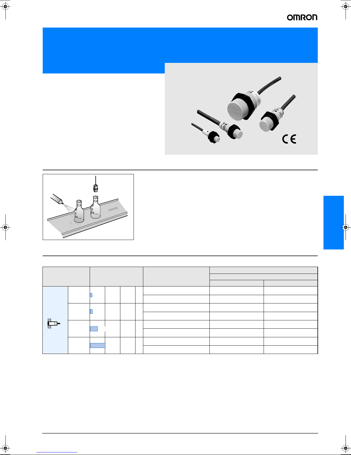
Cylindrical Proximity Sensor in Plastic Housing
E2F
• High quality full body plastic housing for high water
proof requirements
• Polyarylate housing for light chemical resistance
Applications
Detection of bottle caps
Warm water
cleaning
High humidity environment
Ordering Information
Sensors
Model Sensing distance Output specifications
NO NC
M8
Shielded
*1. A different frequency type is available. (E2F-X@@5; e.g.E2F-X5E15)
*2. A short-circuit protection type is available. (E2F-X@Y@-53; e.g. E2F-X5Y1-53) Power supply voltage: 100 to 120 VAC
M12
M18
M30
1.5mm
2mm
5mm
10mm
DC 3-wire NPN E2F-X1R5E1 E2F-X1R5E2
AC 2-wire Models E2F-X1R5Y1 E2F-X1R5Y2
DC 3-wire NPN E2F-X2E1 E2F-X2E2
AC 2-wire Models E2F-X2Y1 E2F-X2Y2
DC 3-wire NPN E2F-X5E1 E2F-X5E2
AC 2-wire Models E2F-X5Y1 E2F-X5Y2
DC 3-wire NPN E2F-X10E1 E2F-X10E2
AC 2-wire Models E2F-X10Y1 E2F-X10Y2
*1 *1
*1
*1
*1
*2
*1
*1
*2
Model
Operating status
E2F
*1
*1
*1
*2
*1
*1
*2
Accessories (Order Separately)
D-29E2F
Page 2
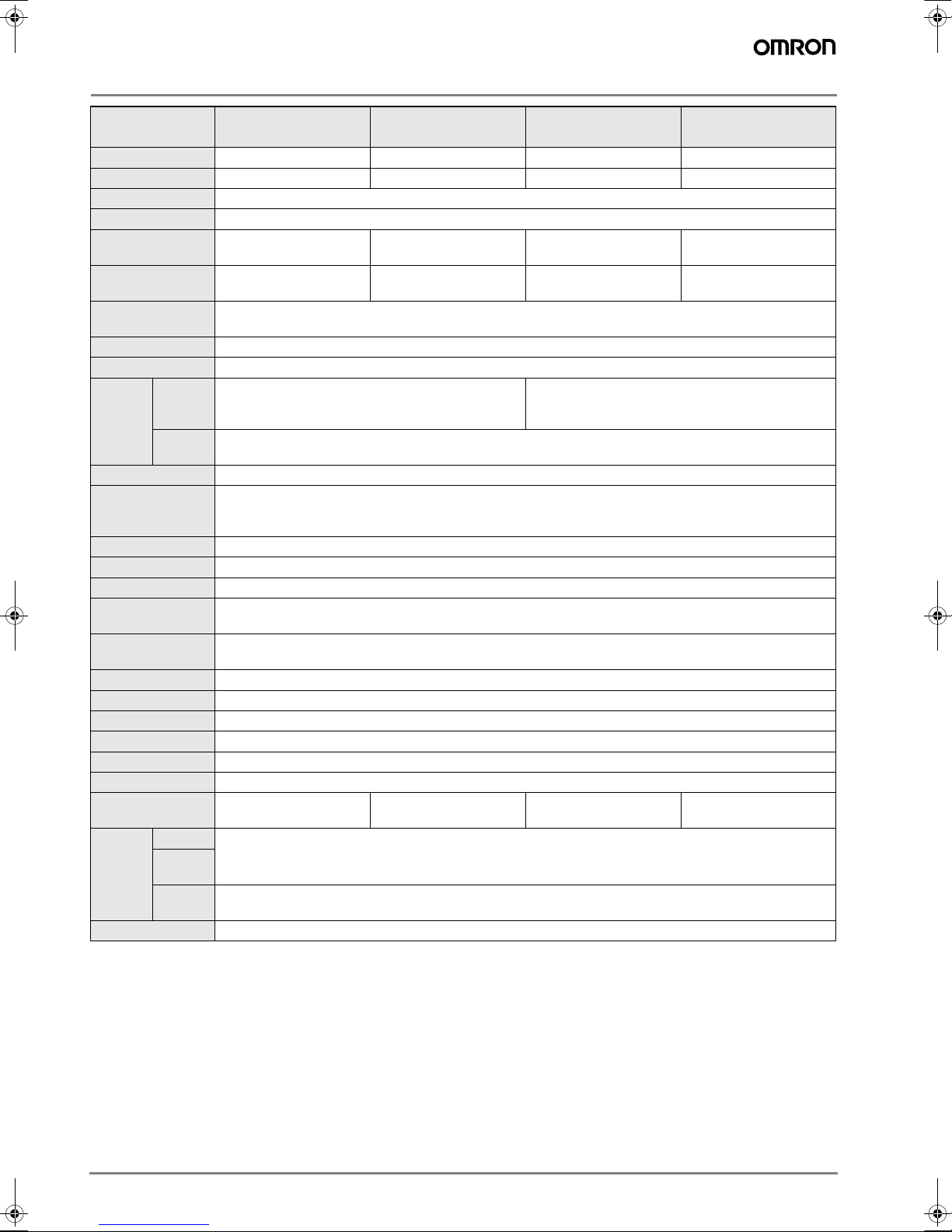
Rating/performance
Model
Item
Sensing distance 1.5 mm ±10% 2 mm ±10% 5 mm ±10% 10 mm ±10%
Setting distance 0 to 1.2 mm 0 to 1.6 mm 0 to 4 mm 0 to 8 mm
Differential distance 10% max.
Sensing object Ferrous metal (Sensitivity lowers with non-ferrous metals)
Standard sensing
object
Response frequen-
cy*1
Power supply(Oper-
ating voltage range)
Current consumption E models: 17 mA max.
Leakage current Y models: 1.7 mA at 200 VAC
Switch-
Control
output
Indicator lamp E models: Detection indicator (red LED) Y models: Operation indicator (red LED)
Operating status
(with sensing object
approaching)
Protective circuits E models: Reverse connection protection, load short-circuit protection, surge absorber Y models: None
Ambient temperature Operating/Storage: -25° C to 70°C (with no icing or condensation)
Ambient humidity Operating/Storage: 35% to 95%RH
Temperature influ-
ence
Voltage influence
Insulation resistance 50 MΩ min. (at 500 VDC) between current carry parts and case
Dielectric strength E models: 1,000 VAC, 50/60 Hz for 1 min between current carry parts and case
Vibration resistance 10 to 55 Hz, 1.5-mm double amplitude for 2 hours each in X, Y, and Z directions
Shock resistance Destruction: 1,000 m/s2 for 10 times each in X, Y, and Z directions
Protective structure IEC IP67
Connection method Pre-wired models (standard length: 2 m)
Weight (Packed
state)
Material
Accessories Instruction manual
*1. The response frequencies are average values measured on condition that the distance between each sensing object is twice as large as the size of the sensing
ing capacity
Residual
voltage
Case
Sensing
surface
Clamp-
ing nut
object and the sensing distance set is half of the maximum sensing distance.
E2F-X1R5E@
E2F-X1R5Y@
Iron, 8 × 8 × 1 mm Iron, 12 × 12 × 1 mm Iron, 18 × 18 × 1 mm Iron, 30 × 30 × 1 mm
E models: 2 kHz, Y mod-
els: 25 Hz
E models: 12 to 24 VDC (10 to 30 VDC), ripple (p-p): 10% max.
Y models: 24 to 240 VAC (20 to 264 VAC)
E models: 200 mA max. Y models: 5 to 100 mA E models: 200 mA max. Y models: 5 to 300 mA
E models: 2 V max. (load current: 200 mA with cable length: 2 m)
Y models: Refer to the Specifications
E1, Y1 models: ON
E2, Y2 models: NC
A maximum fluctuation of ±10% max. of sensing distance at 23°C in temperature range of -25°C and 70° C
E models: ±2.5% max. of sensing distance within a range of ±15% of rated power supply voltage Y models: ±1%
max. of sensing distance within a range of ±10% of rated power supply voltage
Approx.40g Approx. 50 g Approx. 130 g Approx. 170 g
Polyallylate resin
E2F-X2E@
E2F-X2Y@
E models: 1.5 kHz, Y mod-
els: 25 Hz
Polyarylate
E2F-X5E@
E2F-X5Y@
E models: 600 Hz, Y mod-
els: 25 Hz
E2F-X10E@
E2F-X10Y@
E models: 400 Hz, Y mod-
els: 25 Hz
D-30 Inductive Sensors
Page 3

Characteristic data (typical)
n
l
s
s
3
Sensing Distance vs. Sensing Object
E2F-X1R5@@ E2F-X2@@
2.5
#
d
t
mm
=1
2.0
1.5
Sensing distance X (mm)
1.0
0.5
0 5 10 15
X
Side length of sensi
Mild
Stain
(SUS
Bras
Alum
2.4
#d
2.2
2
1.8
1.6
1.4
Sensing distance X (mm)
1.2
1
0.8
0.6
0.4
0.2
0 5 10 15
E2F-X5@@ E2F-X10@@
7
#
d
t
mm
=1
6
5
4
Sensing distance X (mm)
3
2
1
0 5 10 15 20 25 30
X
Side length of sensi
12
#
d
11
X
10
9
8
7
Sensing distance X (mm)
6
5
4
3
2
1
0 102030405060
Output Circuit Diagram
t
mm
=1
X
Side length of sensin
t
mm
=1
Side length of sensing object d (mm)
Mild steel
Stainless steel
(SUS304)
Brass
Aluminum
E2F
Output
DC 3-
wire
AC 2-
wire
Models
Operating
status
NO
NC
NO
NC
Model Timing chart Output circuit
Yes
No
Operates
Reset
ON
OFF
Yes
No
Operates
Reset
H
L
ON
OFF
Yes
No
Operates
Reset
ON
OFF
Yes
No
Operates
Reset
ON
OFF
H
L
Main
circuit
*1. 200 mA max. (source current)
*2. When connecting to the transistor circuit.
Main
circuit
100W
4.7kW
E2F-X1R5E1
E2F-X2E1
E2F-X5E1
E2F-X10E1
E2F-X1R5E2
E2F-X2E2
E2F-X5E2
E2F-X10E2
E2F-X1R5Y1
E2F-X2Y1
E2F-X5Y1
E2F-X10Y1
E2F-X1R5Y2
E2F-X2Y2
E2F-X5Y2
E2F-X10Y2
Sensing object
Load (between brown
and black leads)
Output voltage
(between black and
blue leads)
Detection indicator
Sensing object
Load (between brown
and black leads)
Output voltage
(between black and
blue leads)
Detection indicator
Sensing object
Load
Detection indicator
Sensing object
Load
Detection indicator
2.2W
Brown
Black
Output
*2
Blue
Brown
Blue
+V
Load
*1
Tr
0V
Load
D-31E2F
Page 4

Precautions
Correct Use
Design
Effects of Surrounding Metal
Provide a minimum distance as shown in the table below between the Sensor and the surrounding metal.
l
Mounting
Do not apply excessive torque when tightening any nuts.
Model Tensile strength (torque)
E2F-X1R5@@
E2F-X2@@
E2F-X5@@
E2F-X10@@
0.78 N•m
2 N•m
d dia.
m
Effects of Surrounding Metal(Unit: mm)
Model Item l d D m n
E2F-X1R5@@
E2F-X2@@ 12 8 18
E2F-X5@@ 18 20 27
E2F-X10@@ 30 40 45
0
D
8
0
n
m
l
4.5 12
Mutual Interference
When installing two or more Sensors face-to-face or side-byside, ensure that the minimum distances given in the following
table are maintained.
A
Mutual Interference (Unit: mm)
Model Item A B
E2F-X1R5@@ 20 15
E2F-X2@@ 30 (20) 20(12)
E2F-X5@@ 50 (30) 35 (18)
E2F-X10@@ 100(50) 70(35)
Note: Figures in parentheses are for an E2F used in combination with an E2F
(i.e., E2F-X@@@5) that is operating at a different frequency.
B
● Maintenance and Inspection
Do not use the AC 2-wire models (sensing surface is broken),
where directly exposed to water. There is fear of an electric
shock.
D-32 Inductive Sensors
Page 5

Dimensions (Unit: mm)
DC 3-wire Models AC 2-wire Models
E2F-X1R5E@
E2F-X2E@
15 dia.
13
E2F-X1R5Y@
30
22
20
4
Two, washers
Indicator
Two, clamping nuts
M8 x 1
Note:
Vinyl-insulated round cord, 3.5 dia.,
3 cores (0.12 dia. x 13); Standard length: 2m
15 dia.
13
(see note)
M8 x 1
40
32
29
Indicator
Two, clamping nuts
4
Note:
Vinyl-insulated round cord, 3.5 dia.,
3 cores (0.12 dia. x 13); Standard length: 2m
Two, washers
(see note)
E2F-X2Y@
38
27
17
24
M12 x 1
Note:
Oil-and vibration-resistant,
vinyl-insulated round cord, 6 dia.,
0.5 dia. x 3 cores; Standard length: 2m
The cord can be extended up to 200 m
in an independent metal conduit.
Two, clamping nuts
4
Indicator
17
(see note)
M12 x 1
43
32
29
(see note)
Indicator
Two, clamping nuts
4
Note:
Oil-and vibration-resistant,
vinyl-insulated round cord, 6 dia.,
0.5 dia. x 2 cores; Standard length: 2m
The cord can be extended up to 200 m
in an independent metal conduit.
E2F-X5E@
E2F-X5Y@
E2F
47
40
24
M30 x 1.5
32
29
Indicator
Two, clamping nuts
4
Note:
Oil-and vibration-resistant,
vinyl-insulated round cord, 6 dia.,
0.5 dia. x 2 cores; Standard length: 2m
The cord can be extended up to 200 m
in an independent metal conduit.
24
(see note)
M18 x 1
47
40
32
29
Indicator
Two, clamping nuts
4
Note:
Oil-and vibration-resistant,
vinyl-insulated round cord, 6 dia.,
0.5 dia. x 2 cores; Standard length: 2m
The cord can be extended up to 200 m
in an independent metal conduit.
(see note)
D-33E2F
Page 6

E2F-X10E@
57
E2F-X10Y@
36
M30 x 1.5
Note:
Oil-and vibration-resistant,
vinyl-insulated round cord, 6 dia.,
0.5 dia. x 3 cores; Standard length: 2m
The cord can be extended up to 200 m
in an independent metal conduit.
Mounting Hole Dimension
F
57
50
41
38
Two, clamping nuts
5
Indicator
(see note)
36
M30 x 1.5
Note:
Oil-and vibration-resistant,
vinyl-insulated round cord, 6 dia.,
0.5 dia. x 2 cores; Standard length: 2m
The cord can be extended up to 200 m
in an independent metal conduit.
50
41
38
Two, clamping nuts
5
Model E2F-X1R5@@ E2F-X2@@ E2F-X5@@ E2F-X10@@
F (mm)
8.5-mm dia. 12.5-mm dia. 18.5-mm dia. 30.5-mm dia.
+0 +0 +0 +0
(see note)
Indicator
ALL DIMENSIONS SHOWN ARE IN MILLIMETERS.
To convert millimeters into inches, multiply by 0.03937. To convert grams into ounces, multiply by 0.03527.
Cat. No. D07E-EN-01
In the interest of product improvement, specifications are subject to change without notice.
D-34 Inductive Sensors
 Loading...