

Page 1
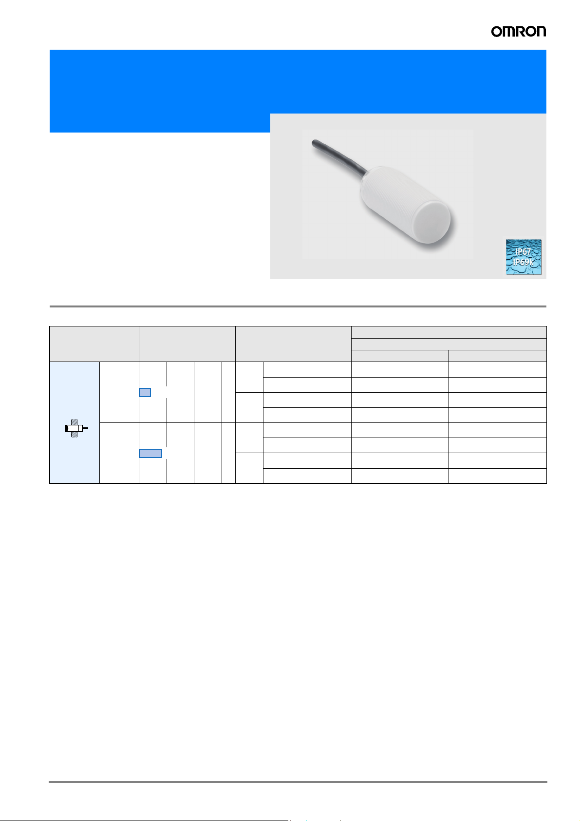
Cylindrical Proximity Sensor in Antimicrobial Plastic Housing
E2F-D
• Bacteria reducing additive in plastic housing for improved machine hygiene
• IP69k tested and certified for highest water resistance
Ordering Information
Sensors
Model Sensing distance Output specifications
NO NC
DC 3-wire PNP E2F-DX4MF1 2M E2F-DX4MF2 2M
short
DC 3-wire NPN E2F-DX4ME1 2M E2F-DX4ME2 2M
DC 3-wire PNP E2F-DX4MF1-L 2M E2F-DX4MF2-L 2M
long
DC 3-wire NPN E2F-DX4ME1-L 2M E2F-DX4ME2-L 2M
DC 3-wire PNP E2F-DX8MF1 2M E2F-DX8MF2 2M
short
DC 3-wire NPN E2F-DX8ME1 2M E2F-DX8ME2 2M
DC 3-wire PNP E2F-DX8MF1-L 2M E2F-DX8MF2-L 2M
long
DC 3-wire NPN E2F-DX8ME1-L 2M E2F-DX8ME2-L 2M
Unshielded
M12
M18
4 mm
8 mm
Model
Operating status
1E2F
Page 2
Rating/performance
Item E2F-DX4M@ E2F-DX8M@
Sensing distance Sn 4 mm ±10%, non shielded 8 mm ±10%, non shielded
Setting distance 0 to 3.2 mm 0 to 6.4 mm
Sensing object Ferrous metal (Sensitivity lowers with non-ferrous metals)
Standard sensing object Iron, 12 × 12 × 1 mm Iron, 24 × 24 × 1 mm
Operating voltage 10 to 35 VDC
Rated supply voltage 12 to 24 VDC, ripple(p-p): 10% max.
Current consumption max. 15 mA at 24 VDC
Differential travel >1%...<15% of sensing distance
Response frequency 2,000 Hz 1,000 Hz
Control output E1 type: NPN-NO E2 type: NPN-NC
F1 type: PNP-NO F2 type: PNP-NC
Control output
max. 300 mA
(switching capacity)
Residual voltage max. 2.5 VDC at 300 mA
Circuit protection Reverse polarity, output short circuit
Indicator Operating indicator (yellow LED)
Ambient temperature Operating/Storage: -25° to 70 ° C
Ambient humidity Operating/Storage: 35% to 95% RH
Temperature influence ±10% max. of Sn at 23 ° C in temperature range of -25 to 70 ° C
Insulation resistance 50 MΩ min. (at 500 VDC) between current carry parts and case
Dielectric strength 1,500 VAC, 50/60 Hz for 1 min between current carry parts and case
Electromagnetic
EN 60947-5-2
compatibility EMC
Vibration resistance 10 to 70 Hz, 1.5 mm double amplitude for 1 hour each in X, Y, and Z directions
Shock resistance Destruction: 300 m/s2 (approx. 30 G) for 6 times each in X, Y, and Z directions
Enclosure rating IP67, IP69k
Connection method Pre-wired models PVC (standard length: 2 m) 3 x 0.25 mm²
Weight 56 g 65 g
Material Case PBT with antimicrobial additive based on silver ions
Nuts PA with antimicrobial additive based on silver ions
E1 type: NPN-NO E2 type: NPN-NC
F1 type: PNP-NO F2 type: PNP-NC
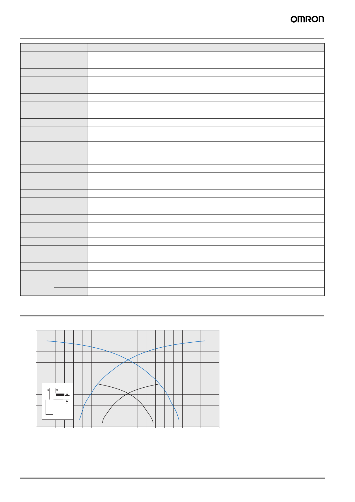
Characteristic data (typical)
Sensing Distance vs. Sensing Object
9,00
8,00
7,00
6,00
5,00
4,00
3,00
Sensing Distance X/mm
2,00
1,00
0,00
-10,00 -9,00 -8,00 -7,00 -6,00 -5,00 -4,00 -3,00 -2,00 -1,00 0,00 1,00 2,00 3,00 4,00 5,00 6,00 7,00 8,00 9,00 10,00
Y
X
Sensor
Distance Y/mm
M18 non-shielded 8mm
M12 non-shielded 4mm
2 Inductive Sensors
Page 3

Output Circuit Diagram
Output Model Timing chart Output circuit
NPN E2F-DX@E@
Sensing object
Yellow indicator
Control output
Yes
Not lit
ON
OFF
NO
No
Lit
NC
Main
circuit
4,7 k
Brown 1
Ω
Load
Black 4 (or 2)
Blue 3
PNP E2F-DX@F@
Sensing object
Yellow indicator
Control output
Yes
No
Not lit
ON
OFF
NO
Lit
NC
Dimensions (Unit: mm)
E2F-DX4M@ 2M E2F-DX8M@ 2M
Ø 3.9
M12x1
41
E2F-DX4M@-L 2M E2F-DX8M@-L 2M
Ø 3.9
M12x1
52,5
M18x1
M18x1
Brown 1
Ω
Black 4 (or 2)
Load
Blue 3
Ø 3.9
0 V
Ø 3.9
Main
circuit
4,7 k
72.5
60
Precautions
Safety Precautions
Power Supply
Do not impose an excessive voltage on the E2F-D, otherwise it may
be damaged. Do not impose AC current (100 to 240 VAC) on any DC
model, otherwise it may be damaged.
Load Short-circuit
Do not short-circuit the load, or the E2F-Dmay be damaged.
The E2F-D’s short-circuit protection function will be valid if the polarity of the supply voltage imposed is correct and within the rated voltage range.
72.5
Wiring
Be sure to wire the E2F-D and load correctly, otherwise it may be
damaged.
Connection with No Load
Be sure to insert loads when wiring. Make sure to connect a proper
load to the E2F-D in operation, otherwise it may damage internal elements.
Do not expose the product to flammable or explosive gases.
Do not disassemble, repair, or modify the product.
3E2F
Page 4

Correct Use
Designing
Power Reset Time
The Proximity Sensor is ready to operate within 100 ms after power
is supplied. If power supplies are connected to the Proximity Sensor
and load respectively, be sure to supply power to the Proximity Sensor before supplying power to the load.
Effects of Surrounding Metal
When mounting the E2F-D within a metal panel, ensure that the
clearances given in the following table are maintained.
l
n
m
l
(Unit: mm)
Typ e
Non-shielded
d dia.
D
m
Dimension
l15 22
m20 48
d40 70
D15 22
n40 70
M12 M18
Power OFF
The Proximity Sensor may output a pulse signal when it is turned
OFF. Therefore, it is recommended that the load be turned OFF
before turning OFF the Proximity Sensor.
Power Supply Transformer
When using a DC power supply, make sure that the DC power supply
has an insulated transformer. Do not use a DC power supply with an
auto-transformer.
Wiring
High-tension Lines
Wiring through Metal Conduit:
If there is a power or high-tension line near the cable of the Proximity
Sensor, wire the cable through an independent metal conduit to prevent against Proximity Sensor damage or malfunctioning.
Cable Extension
Standard cable length is less than 200 m.
The tractive force is 50 N.
Mounting
The Proximity Sensor must not be subjected to excessive shock with
a hammer when it is installed, otherwise the Proximity Sensor may
be damaged or lose its water-resistivity.
Do not tighten the nut with excessive force. A washer must be used
with the nut.
Type Torque
M12 1.5 Nm
M18 2.0 Nm
Maintenance and Inspection
Periodically perform the following checks to ensure stable operation
of the Proximity Sensor over a long period of time.
1. Check for mounting position, dislocation, looseness, or distortion
of the Proximity Sensor and sensing objects.
2. Check for loose wiring and connections, improper contacts, and
line breakage.
3. Check for attachment or accumulation of metal powder or dust.
4. Check for abnormal temperature conditions and other environmental conditions.
5. Check for proper lighting of indicators (for models with a set indicator.)
Never disassemble or repair the Sensor.
Environment
Water Resistivity
The Proximity Sensors are tested intensively on water resistance, but
in order to ensure maximum performance and life expectancy avoid
immersion in water and provide protection from rain or snow.
Operating Environment
Ensure storage and operation of the Proximity Sensor within the
given specifications.
Inrush Current
A load that has a large inrush current (e.g., a lamp or motor) will
damage the Proximity Sensor, in which case connect the load to the
Proximity Sensor through a relay.
<SUITABILITY FOR USE>
OMRON shall not be responsible for conformity with any standards, codes, or regulations that apply to the combination of the products in the
customer’s application or use of the products.
Take all necessary steps to determine the suitability of the product for the systems, machines, and equipment with which it will be used.
<CHANGE IN SPECIFICATIONS>
Product specifications and accessories may be changed at any time based on improvements and other reasons. Consult with your OMRON
representative at any time to confirm actual specifications of purchased product.
In the interest of product improvement, specifications are subject to change without notice.Cat. No. D15E-EN-01
OMRON EUROPE B.V.
Wegalaan 67-69,
NL-2132 JD, Hoofddorp,
The Netherlands
Phone: +31 23 568 13 00
Fax: +31 23 568 13 88
www.eu.omron.com
4 Inductive Sensors
 Loading...