

Page 1

Welding Proximity Sensor
(3) (4) (5) (6)
E2EW
(1) (2)
X
-
(7)
-
(8)
E2EW Series
DC 3-wire
Stable detection in lines containing both
aluminum and iron
• Equivalent sensing distances for both iron and aluminum
• Enables common design for lines with both iron and aluminum
1
1
• The exceptional sensing range 2, which means fewer false
detections and thereby fewer unexpected stoppages.
• OMRON’s unique fluororesin coating technologies enable long-
4
lasting spatter resistance
, eliminates the need to replace for 10
years 3.
• Durable full metal body to reduce unexpected downtime
1
• 2-output (NO+NC) models and models with IO-Link
are also
available.
• Laser printed information (sensing distance on the sensor head,
model on the cable, and model on the metal part of the connector
model) reduce errors during sensor replacement.
5
• Weld field immunity cancels pulse noise from magnetic fields.
• UL certification (UL60947-5-2) and
For the most recent information on models that have been
certified for safety standards, refer to your OMRON website.
1
Be sure to read Safety Precautions on page 23.
CSA certification (CSA C22.2 UL60947-5-2-14)
1. PREMIUM Models only.
2. Based on November 2020 OMRON investigation.
3. This value assumes that the sensor operates 10 hours a day in an arc welding
environment and is cleaned once a month (12 times a year).
If our previous model (E2EF-Q) needs to be replaced once every 3 times it is cleaned, the E2EW-Q Proximity Sensor needs to be replaced
once every 180 times it is cleaned. This means that there is no need to replace the E2EW-Q Proximity Sensor for 10 or more years.
4. Models with spatter-resistant coating only.
5. Models without spatter-resistant coating only.
E2EW Series Model Number Legend
DC 3-wire
No. Type Code Meaning
(1) Case
(2) Sensing distance Number Sensing distance (Unit: mm)
(3) Output configuration
(4) Operation mode
(5) IO-Link baud rate
(6) Size
(7) Connection method
(8) Cable length Number M Cable length
Note: The purpose of this model number legend is to provide understanding of the meaning of specifications from the model number.
Models are not available for all combinations of code numbers.
Blank Without spatter-resistant coating
Q With spatter-resistant coating
B PNP open collector
C NPN open collector
1 Normally open (NO)
2 Normally closed (NC)
3 Normally open, Normally closed (NO+NC)
Blank Non IO-Link compliant
D COM2 (38.4kbps)
T COM3 (230.4kbps)
12 M12
18 M18
30 M30
Blank Pre-wired Models
M1 M12 Connector Models
M1TJ M12 Pre-wired Smartclick Connector Models
1
Page 2

E2EW Series
Ordering Information
PREMIUM Model
E2EW Series (Quadruple distance model)
DC 3-wire [Refer to Dimensions on page 26.]
Shielded
(Sensing distance)
1. When embedding the Proximity Sensor in metal, refer to Influence of Surrounding Metal on page 24.
2. Models with 5-m cable length are also available with "5M" suffix. (Example: E2EW-X7B1T12 5M)
Note: 1. Models in are equipped with IO-Link (COM3). For IO-Link (COM2), select a model number with the format of "E2EW-X
1
Size
M12
(7 mm)
M18
(12 mm)
M30
(22 mm)
Connection method Operation mode
Pre-wired (2 m)
M12 Pre-wired
Smartclick Connector (0.3 m)
M12 Connector
Pre-wired (2 m)
M12 Pre-wired
Smartclick Connector (0.3 m)
M12 Connector
Pre-wired (2 m)
M12 Pre-wired
Smartclick Connector (0.3 m)
M12 Connector
2
2
2
NO E2EW-X7B1T12 2M E2EW-X7C112 2M
NC E2EW-X7B212 2M E2EW-X7C212 2M
NO+NC
NO
NC E2EW-X7B212-M1TJ 0.3M E2EW-X7C212-M1TJ 0.3M
NO+NC
NO
NC E2EW-X7B212-M1 E2EW-X7C212-M1
NO+NC
NO E2EW-X12B1T18 2M E2EW-X12C118 2M
NC E2EW-X12B218 2M E2EW-X12C218 2M
NO+NC
NO
NC E2EW-X12B218-M1TJ 0.3M E2EW-X12C218-M1TJ 0.3M
NO+NC
NO
NC E2EW-X12B218-M1 E2EW-X12C218-M1
NO+NC
NO E2EW-X22B1T30 2M E2EW-X22C130 2M
NC E2EW-X22B230 2M E2EW-X22C230 2M
NO+NC
NO
NC E2EW-X22B230-M1TJ 0.3M E2EW-X22C230-M1TJ 0.3M
NO+NC
NO
NC E2EW-X22B230-M1 E2EW-X22C230-M1
NO+NC
E2EW-X7B3T12 2M E2EW-X7C312 2M
E2EW-X7B1T12-M1TJ 0.3M E2EW-X7C112-M1TJ 0.3M
E2EW-X7B3T12-M1TJ 0.3M E2EW-X7C312-M1TJ 0.3M
E2EW-X7B1T12-M1 E2EW-X7C112-M1
E2EW-X7B3T12-M1 E2EW-X7C312-M1
E2EW-X12B3T18 2M E2EW-X12C318 2M
E2EW-X12B1T18-M1TJ 0.3M E2EW-X12C118-M1TJ 0.3M
E2EW-X12B3T18-M1TJ 0.3M E2EW-X12C318-M1TJ 0.3M
E2EW-X12B1T18-M1 E2EW-X12C118-M1
E2EW-X12B3T18-M1 E2EW-X12C318-M1
E2EW-X22B3T30 2M E2EW-X22C330 2M
E2EW-X22B1T30-M1TJ 0.3M E2EW-X22C130-M1TJ 0.3M
E2EW-X22B3T30-M1TJ 0.3M E2EW-X22C330-M1TJ 0.3M
E2EW-X22B1T30-M1 E2EW-X22C130-M1
E2EW-X22B3T30-M1 E2EW-X22C330-M1
(Example: E2EW-X7B1D12 2M).
Operation mode NO can be changed to NC via IO-Link communications.
2. IO-Link is not supported for NC-type PNP outputs or all types of NPN outputs.
Model
PNP NPN
D
"
2
Page 3

PREMIUM Model
E2EW Series (Triple distance model)
DC 3-wire [Refer to Dimensions on page 26.]
Shielded
(Sensing distance)
1. When embedding the Proximity Sensor in metal, refer to Influence of Surrounding Metal on page 24.
2. Models with 5-m cable length are also available with "5M" suffix. (Example: E2EW-X6B1T12 5M)
Note: 1.
1
Size
M12
(6 mm)
M18
(10 mm)
M30
(20 mm)
Models in
X
D" (Example: E2EW-X6B1D12 2M).
Connection method Operation mode
NO E2EW-X6B1T12 2M E2EW-X6C112 2M
Pre-wired (2 m)
M12 Pre-wired
Smartclick Connector (0.3 m)
M12 Connector
Pre-wired (2 m)
M12 Pre-wired
Smartclick Connector (0.3 m)
M12 Connector
Pre-wired (2 m)
M12 Pre-wired
Smartclick Connector (0.3 m)
M12 Connector
2
2
2
NC E2EW-X6B212 2M E2EW-X6C212 2M
NO+NC
NO
NC E2EW-X6B212-M1TJ 0.3M E2EW-X6C212-M1TJ 0.3M
NO+NC
NO
NC E2EW-X6B212-M1 E2EW-X6C212-M1
NO+NC
NO E2EW-X10B1T18 2M E2EW-X10C118 2M
NC E2EW-X10B218 2M E2EW-X10C218 2M
NO+NC
NO
NC E2EW-X10B218-M1TJ 0.3M E2EW-X10C218-M1TJ 0.3M
NO+NC
NO
NC E2EW-X10B218-M1 E2EW-X10C218-M1
NO+NC
NO E2EW-X20B1T30 2M E2EW-X20C130 2M
NC E2EW-X20B230 2M E2EW-X20C230 2M
NO+NC
NO
NC E2EW-X20B230-M1TJ 0.3M E2EW-X20C230-M1TJ 0.3M
NO+NC
NO
NC E2EW-X20B230-M1 E2EW-X20C230-M1
NO+NC
E2EW-X6B3T12 2M E2EW-X6C312 2M
E2EW-X6B1T12-M1TJ 0.3M E2EW-X6C112-M1TJ 0.3M
E2EW-X6B3T12-M1TJ 0.3M E2EW-X6C312-M1TJ 0.3M
E2EW-X6B1T12-M1 E2EW-X6C112-M1
E2EW-X6B3T12-M1 E2EW-X6C312-M1
E2EW-X10B3T18 2M E2EW-X10C318 2M
E2EW-X10B1T18-M1TJ 0.3M E2EW-X10C118-M1TJ 0.3M
E2EW-X10B3T18-M1TJ 0.3M E2EW-X10C318-M1TJ 0.3M
E2EW-X10B1T18-M1 E2EW-X10C118-M1
E2EW-X10B3T18-M1 E2EW-X10C318-M1
E2EW-X20B3T30 2M E2EW-X20C330 2M
E2EW-X20B1T30-M1TJ 0.3M E2EW-X20C130-M1TJ 0.3M
E2EW-X20B3T30-M1TJ 0.3M E2EW-X20C330-M1TJ 0.3M
E2EW-X20B1T30-M1 E2EW-X20C130-M1
E2EW-X20B3T30-M1 E2EW-X20C330-M1
are equipped with IO-Link (COM3). For IO-Link (COM2), select a model number with the format of "E2EW-
Operation mode NO can be changed to NC via IO-Link communications.
2. IO-Link is not supported for NC-type PNP outputs or all types of NPN outputs.
PNP NPN
E2EW Series
Model
3
Page 4

E2EW Series
PREMIUM Model
E2EW-Q Series (Spatter-resistant Quadruple distance model)
DC 3-wire [Refer to Dimensions on page 26.]
Shielded
(Sensing distance)
1. When embedding the Proximity Sensor in metal, refer to Influence of Surrounding Metal on page 24.
2. Models with 5-m cable length are also available with "5M" suffix. (Example: E2EW-QX7B1T12 5M)
Note: 1.
1
Size
M12
(7 mm)
M18
(12 mm)
M30
(22 mm)
Connection method Operation mode
Pre-wired (2 m)
M12 Pre-wired
Smartclick Connector (0.3 m)
M12 Connector
Pre-wired (2 m)
M12 Pre-wired
Smartclick Connector (0.3 m)
M12 Connector
Pre-wired (2 m)
M12 Pre-wired
Smartclick Connector (0.3 m)
M12 Connector
2
2
2
PNP NPN
NO E2EW-QX7B1T12 2M E2EW-QX7C112 2M
NC E2EW-QX7B212 2M E2EW-QX7C212 2M
NO+NC
NO
NC E2EW-QX7B212-M1TJ 0.3M E2EW-QX7C212-M1TJ 0.3M
NO+NC
NO
NC E2EW-QX7B212-M1 E2EW-QX7C212-M1
NO+NC
NO E2EW-QX12B1T18 2M E2EW-QX12C118 2M
NC E2EW-QX12B218 2M E2EW-QX12C218 2M
NO+NC
NO
NC E2EW-QX12B218-M1TJ 0.3M E2EW-QX12C218-M1TJ 0.3M
NO+NC
NO
NC E2EW-QX12B218-M1 E2EW-QX12C218-M1
NO+NC
NO E2EW-QX22B1T30 2M E2EW-QX22C130 2M
NC E2EW-QX22B230 2M E2EW-QX22C230 2M
NO+NC
NO
NC E2EW-QX22B230-M1TJ 0.3M E2EW-QX22C230-M1TJ 0.3M
NO+NC
NO
NC E2EW-QX22B230-M1 E2EW-QX22C230-M1
NO+NC
E2EW-QX7B3T12 2M E2EW-QX7C312 2M
E2EW-QX7B1T12-M1TJ 0.3M E2EW-QX7C112-M1TJ 0.3M
E2EW-QX7B3T12-M1TJ 0.3M E2EW-QX7C312-M1TJ 0.3M
E2EW-QX7B1T12-M1 E2EW-QX7C112-M1
E2EW-QX7B3T12-M1 E2EW-QX7C312-M1
E2EW-QX12B3T18 2M E2EW-QX12C318 2M
E2EW-QX12B1T18-M1TJ 0.3M E2EW-QX12C118-M1TJ 0.3M
E2EW-QX12B3T18-M1TJ 0.3M E2EW-QX12C318-M1TJ 0.3M
E2EW-QX12B1T18-M1 E2EW-QX12C118-M1
E2EW-QX12B3T18-M1 E2EW-QX12C318-M1
E2EW-QX22B3T30 2M E2EW-QX22C330 2M
E2EW-QX22B1T30-M1TJ 0.3M E2EW-QX22C130-M1TJ 0.3M
E2EW-QX22B3T30-M1TJ 0.3M E2EW-QX22C330-M1TJ 0.3M
E2EW-QX22B1T30-M1 E2EW-QX22C130-M1
E2EW-QX22B3T30-M1 E2EW-QX22C330-M1
Models in are equipped with IO-Link (COM3). For IO-Link (COM2), select a model number with the format of "E2EW-QX
(Example: E2EW-QX7B1D12 2M).
Operation mode NO can be changed to NC via IO-Link communications.
2. IO-Link is not supported for NC-type PNP outputs or all types of NPN outputs.
Model
D
"
4
Page 5

PREMIUM Model
E2EW-Q Series (Spatter-resistant Triple distance model)
DC 3-wire [Refer to Dimensions on page 26.]
Shielded
(Sensing distance)
1. When embedding the Proximity Sensor in metal, refer to Influence of Surrounding Metal on page 24.
2. Models with 5-m cable length are also available with "5M" suffix. (Example: E2EW-QX6B1T12 5M)
Note: 1.
1
Size
M12
(6 mm)
M18
(10 mm)
M30
(20 mm)
Connection method Operation mode
Pre-wired (2 m)
M12 Pre-wired
Smartclick Connector (0.3 m)
M12 Connector
Pre-wired (2 m)
M12 Pre-wired
Smartclick Connector (0.3 m)
M12 Connector
Pre-wired (2 m)
M12 Pre-wired
Smartclick Connector (0.3 m)
M12 Connector
2
2
2
PNP NPN
NO E2EW-QX6B1T12 2M E2EW-QX6C112 2M
NC E2EW-QX6B212 2M E2EW-QX6C212 2M
NO+NC
NO
NC E2EW-QX6B212-M1TJ 0.3M E2EW-QX6C212-M1TJ 0.3M
NO+NC
NO
NC E2EW-QX6B212-M1 E2EW-QX6C212-M1
NO+NC
NO E2EW-QX10B1T18 2M E2EW-QX10C118 2M
NC E2EW-QX10B218 2M E2EW-QX10C218 2M
NO+NC
NO
NC E2EW-QX10B218-M1TJ 0.3M E2EW-QX10C218-M1TJ 0.3M
NO+NC
NO
NC E2EW-QX10B218-M1 E2EW-QX10C218-M1
NO+NC
NO E2EW-QX20B1T30 2M E2EW-QX20C130 2M
NC E2EW-QX20B230 2M E2EW-QX20C230 2M
NO+NC
NO
NC E2EW-QX20B230-M1TJ 0.3M E2EW-QX20C230-M1TJ 0.3M
NO+NC
NO
NC E2EW-QX20B230-M1 E2EW-QX20C230-M1
NO+NC
E2EW-QX6B3T12 2M E2EW-QX6C312 2M
E2EW-QX6B1T12-M1TJ 0.3M E2EW-QX6C112-M1TJ 0.3M
E2EW-QX6B3T12-M1TJ 0.3M E2EW-QX6C312-M1TJ 0.3M
E2EW-QX6B1T12-M1 E2EW-QX6C112-M1
E2EW-QX6B3T12-M1 E2EW-QX6C312-M1
E2EW-QX10B3T18 2M E2EW-QX10C318 2M
E2EW-QX10B1T18-M1TJ 0.3M E2EW-QX10C118-M1TJ 0.3M
E2EW-QX10B3T18-M1TJ 0.3M E2EW-QX10C318-M1TJ 0.3M
E2EW-QX10B1T18-M1 E2EW-QX10C118-M1
E2EW-QX10B3T18-M1 E2EW-QX10C318-M1
E2EW-QX20B3T30 2M E2EW-QX20C330 2M
E2EW-QX20B1T30-M1TJ 0.3M E2EW-QX20C130-M1TJ 0.3M
E2EW-QX20B3T30-M1TJ 0.3M E2EW-QX20C330-M1TJ 0.3M
E2EW-QX20B1T30-M1 E2EW-QX20C130-M1
E2EW-QX20B3T30-M1 E2EW-QX20C330-M1
Models in are equipped with IO-Link (COM3). For IO-Link (COM2), select a model number with the format of "E2EW-QX
(Example: E2EW-QX6B1D12 2M).
Operation mode NO can be changed to NC via IO-Link communications.
2. IO-Link is not supported for NC-type PNP outputs or all types of NPN outputs.
Model
E2EW Series
D
"
5
Page 6

E2EW Series
BASIC Model
E2EW Series (Single distance model)
DC 3-wire [Refer to Dimensions on page 27.]
Shielded
Size
(Sensing distance)
M12
(2 mm)
M18
(5 mm)
M30
(10 mm)
* Models with 5-m cable length are also available with "5M" suffix. (Example: E2EW-X2B112 5M)
Note: IO-Link is not supported for all types of BASIC Model.
Connection method Operation mode
Pre-wired (2 m) *
M12 Pre-wired
Smartclick Connector (0.3 m)
Pre-wired (2 m) *
M12 Pre-wired
Smartclick Connector (0.3 m)
Pre-wired (2 m) *
M12 Pre-wired
Smartclick Connector (0.3 m)
PNP NPN
NO E2EW-X2B112 2M E2EW-X2C112 2M
NC E2EW-X2B212 2M E2EW-X2C212 2M
NO+NC E2EW-X2B312 2M E2EW-X2C312 2M
NO E2EW-X2B112-M1TJ 0.3M E2EW-X2C112-M1TJ 0.3M
NC E2EW-X2B212-M1TJ 0.3M E2EW-X2C212-M1TJ 0.3M
NO+NC E2EW-X2B312-M1TJ 0.3M E2EW-X2C312-M1TJ 0.3M
NO E2EW-X5B118 2M E2EW-X5C118 2M
NC E2EW-X5B218 2M E2EW-X5C218 2M
NO+NC E2EW-X5B318 2M E2EW-X5C318 2M
NO E2EW-X5B118-M1TJ 0.3M E2EW-X5C118-M1TJ 0.3M
NC E2EW-X5B218-M1TJ 0.3M E2EW-X5C218-M1TJ 0.3M
NO+NC E2EW-X5B318-M1TJ 0.3M E2EW-X5C318-M1TJ 0.3M
NO E2EW-X10B130 2M E2EW-X10C130 2M
NC E2EW-X10B230 2M E2EW-X10C230 2M
NO+NC E2EW-X10B330 2M E2EW-X10C330 2M
NO E2EW-X10B130-M1TJ 0.3M E2EW-X10C130-M1TJ 0.3M
NC E2EW-X10B230-M1TJ 0.3M E2EW-X10C230-M1TJ 0.3M
NO+NC E2EW-X10B330-M1TJ 0.3M E2EW-X10C330-M1TJ 0.3M
Model
6
Page 7

BASIC Model
E2EW-Q Series (Spatter-resistant Single distance model)
DC 3-wire [Refer to Dimensions on page 27.]
Shielded
Size
(Sensing distance)
M12
(2 mm)
M18
(5 mm)
M30
(10 mm)
* Models with 5-m cable length are also available with "5M" suffix. (Example: E2EW-QX2B112 5M)
Note: IO-Link is not supported for all types of BASIC Model.
Connection method Operation mode
Pre-wired (2 m) *
M12 Pre-wired
Smartclick Connector (0.3 m)
Pre-wired (2 m) *
M12 Pre-wired
Smartclick Connector (0.3 m)
Pre-wired (2 m) *
M12 Pre-wired
Smartclick Connector (0.3 m)
PNP NPN
NO E2EW-QX2B112 2M E2EW-QX2C112 2M
NC E2EW-QX2B212 2M E2EW-QX2C212 2M
NO+NC E2EW-QX2B312 2M E2EW-QX2C312 2M
NO E2EW-QX2B112-M1TJ 0.3M E2EW-QX2C112-M1TJ 0.3M
NC E2EW-QX2B212-M1TJ 0.3M E2EW-QX2C212-M1TJ 0.3M
NO+NC E2EW-QX2B312-M1TJ 0.3M E2EW-QX2C312-M1TJ 0.3M
NO E2EW-QX5B118 2M E2EW-QX5C118 2M
NC E2EW-QX5B218 2M E2EW-QX5C218 2M
NO+NC E2EW-QX5B318 2M E2EW-QX5C318 2M
NO E2EW-QX5B118-M1TJ 0.3M E2EW-QX5C118-M1TJ 0.3M
NC E2EW-QX5B218-M1TJ 0.3M E2EW-QX5C218-M1TJ 0.3M
NO+NC E2EW-QX5B318-M1TJ 0.3M E2EW-QX5C318-M1TJ 0.3M
NO E2EW-QX10B130 2M E2EW-QX10C130 2M
NC E2EW-QX10B230 2M E2EW-QX10C230 2M
NO+NC E2EW-QX10B330 2M E2EW-QX10C330 2M
NO E2EW-QX10B130-M1TJ 0.3M E2EW-QX10C130-M1TJ 0.3M
NC E2EW-QX10B230-M1TJ 0.3M E2EW-QX10C230-M1TJ 0.3M
NO+NC E2EW-QX10B330-M1TJ 0.3M E2EW-QX10C330-M1TJ 0.3M
E2EW Series
Model
7
Page 8
E2EW Series
Accessories (Sold Separately)
Sensor I/O Connectors
(Models for Pre-wired Connectors) A Sensor I/O Connector is not provided with the Sensor. It must be ordered separately
as required.
Round Water-resistant Connectors XS2 series
Appearance
M12
Connector
Straight type
Right-angle type
Cable
Specification
PVC robot cable
Type
Sockets on One
Cable End
Socket and Plug
on Cable Ends
Cable
diameter
(mm)
6 dia.
6 dia.
Cable Connection
Direction
Straight
Right-angle
Straight (Socket)/
Straight (Plug)
Right-angle (Socket)/
Right-angle (Plug)
Straight (Socket)/
Right-angle (Plug)
Right-angle (Socket)/
Straight (Plug)
Cable
length
(m)
2 XS2F-M12PVC4S2M
5 XS2F-M12PVC4S5M
10 XS2F-M12PVC4S10M
2 XS2F-M12PVC4A2M
5 XS2F-M12PVC4A5M
10 XS2F-M12PVC4A10M
1 XS2W-D421-C81-F
2 XS2W-D421-D81-F
3 XS2W-D421-E81-F
5 XS2W-D421-G81-F
10 XS2W-D421-J81-F
2 XS2W-D422-D81-F
5 XS2W-D422-G81-F
2 XS2W-D423-D81-F
5 XS2W-D423-G81-F
2 XS2W-D424-D81-F
5 XS2W-D424-G81-F
Sensor I/O Connector
model number
Applicable Proximity
Sensor model number
-M1
E2EW-X
E2EW-QX
E2EW-X
E2EW-QX
-M1
-M1TJ
-M1TJ
8
Page 9

E2EW Series
Ratings and Specifications
PREMIUM Model
E2EW Series (Quadruple/Triple distance model)
E2EW-Q Series (Spatter-resistant Quadruple/Triple distance model)
DC 3-wire
Shielded
Type Quadruple distance model Triple distance model
Size M12 M18 M30 M12 M18 M30
Item Model E2EW-(Q)X712
Sensing distance 7 mm ±10% 12 mm ±10% 22 mm ±10% 6 mm ±10% 10 mm ±10% 20 mm ±10%
Setting distance 0 to 4.9 mm 0 to 8.4 mm 0 to 15.4 mm 0 to 4.2 mm 0 to 7.0 mm 0 to 14 mm
Differential travel 15% max. of sensing distance
Detectable object
Standard sensing object
Response frequency
Power supply voltage 10 to 30 VDC (including 10% ripple (p-p)), Class 2
Current consumption 720 mW max. (Current consumption: 30 mA max. at power supply voltage of 24 V)
Output configuration B Models: PNP open collector, C Models: NPN open collector
Operation mode
Control output
Indicator
Protection circuits
Ambient temperature range Operating: 0 to 85 °C, Storage: -15 to 85 °C (with no icing or condensation)
Ambient humidity range Operating/Storage: 35% to 95% (with no condensation)
Temperature influence ±20% max. of sensing distance at 23 °C in the temperature range of 0 to 85 °C
Voltage influence ±1.5% max. of sensing distance at rated voltage in the rated voltage ±15% range
Insulation resistance 50 M min. (at 500 VDC) between current-carrying parts and case
Dielectric strength 1 ,000 VAC, 50/60 Hz for 1 minute between current-carrying parts and case
Vibration resistance (destruction) 10 to 55 Hz, 1.5-mm double amplitude for 2 hours each in X, Y, and Z directions
Shock resistance (destruction) 1,000 m/s2 10 times each in X, Y, and Z directions
Degree of protection IEC 60529: IP67
Connection method
Weight
(packed state)
Materials
Main IO-Link functions
IO-Link
Communication
specifications
Accessories Instruction manual, Clamping nuts, Toothed washer
1
Load current
Residual voltage
Pre-wired Approx. 140 g Approx. 165 g Approx. 225 g Approx. 140 g Approx. 165 g Approx. 225 g
M12 Pre-wired
Smartclick
Connector
M12 Connector Approx. 60 g Approx. 75 g Approx. 135 g Approx. 60 g Approx. 75 g Approx. 135 g
Case E2EW-X: Stainless steel (SUS303), E2EW-QX: Fluororesin coating (Base material: (SUS303))
Sensing surface E2EW-X: Stainless steel (SUS303), E2EW-QX: Fluororesin coating (Base material: (SUS303))
Sensing surface
(Thickness)
Clamping nuts E2EW-X: Stainless steel (SUS303), E2EW-QX: Fluororesin coating (Base material: (SUS303))
Toothed washers Zinc-plated iron
Cable Vinyl chloride (PVC)
2
IO-Link
specification
Baud rate E2EW(-Q) XBT: COM3 (230.4 kbps), E2EW(-Q) XBD: COM2 (38.4 kbps)
2
Data length PD size: 2 bytes, OD size: 1 byte (M-sequence type: TYPE_2_2)
Minimum cycle
time
Ferrous metals and non-ferrous metals (The sensing distance depends on the material of the sensing object. Refer to
Engineering Data on page 11.)
Iron,
21 × 21 × 1 mm
2 Hz
1-output models (B1, C1): NO (Normally open),
1-output models (B2, C2): NC (Normally closed),
2-output models (B3, C3): NO+NC (Normally open, Normally closed)
1-output models (B1,B2,C1,C2): 10 to 30 VDC, Class 2, 200 mA max.
2-output models (B3, C3): 10 to 30 VDC, Class 2, 100 mA max.
1-output models (B1,B2,C1,C2): 2 V max. (Load current: 200 mA, Cable length: 2 m)
2-output models (B3, C3): 2 V max. (Load current: 100 mA, Cable length: 2 m)
In the Standard I/O mode (SIO mode): Operation indicator (orange, lit) and communication indicator (green, not lit)
In the IO-Link communication mode (COM mode): Operation indicator (orange, lit) and communication indicator (green,
blinking at 1 s intervals)
Power supply reverse polarity protection, Surge suppressor, Output short-circuit protection, Output reverse polarity protection
Pre-wired Models (Standard cable length: 2 m), Pre-wired Connector Models (Standard cable length: 0.3 m),
M12 Connector Models
Approx. 70 g Approx. 100 g Approx. 160 g Approx. 70 g Approx. 100 g Approx. 160 g
0.4 mm 0.4 mm 0.5 mm 0.4 mm 0.4 mm 0.5 mm
Operation mode switching between NO and NC, self diagnosis enabling, excessive proximity judgment distance selecting,
timer function of the control output and timer time selecting, instability output (IO-Link mode) ON delay timer time selecting
function, monitor output, operating hours read-out, readout of the sensor internal temperature, and initial reset
Ver.1.1
COM2: 2.3 ms, COM3: 1.0 ms
1. The response frequency is an average value. Factory setting: (timer function: ONOFF delay)
2. IO-Link is not supported for NC-type PNP outputs or all types of NPN outputs.
3. UL temperature rating is between 0 °C to 60 °C.
E2EW-(Q)X1218 E2EW-(Q)X2230
Iron,
36 × 36 × 1 mm
Iron,
66 × 66 × 1 mm
E2EW-(Q)X612
Iron,
18 × 18 × 1 mm
3
E2EW-(Q)X1018 E2EW-(Q)X2030
Iron,
30 × 30 × 1 mm
Iron,
60 × 60 × 1 mm
9
Page 10
E2EW Series
BASIC Model
E2EW Series (Single distance model)
E2EW-Q Series (Spatter-resistant Single distance model)
DC 3-wire
Shielded
Type Single distance model
Size M12 M18 M30
Item Model E2EW-(Q)X212 E2EW-(Q)X518 E2EW-(Q)X1030
Sensing distance 2 mm ±10% 5 mm ±10% 10 mm ±10%
Setting distance 0 to 1.4 mm 0 to 3.5 mm 0 to 7 mm
Differential travel 10% max. of sensing distance
Detectable object
Standard sensing object
Response frequency
Power supply voltage 10 to 30 VDC (including 10% ripple (p-p)), Class 2
Current consumption
Output configuration
Operation mode
Control output
Indicator Operation indicator (orange, lit) and communication indicator (green, not lit)
Protection circuits
Ambient temperature range Operating: 0 to 85 °C, Storage: -15 to 85 °C (with no icing or condensation)
Ambient humidity range Operating/Storage: 35% to 95% (with no condensation)
Temperature influence ±20% max. of sensing distance at 23 °C in the temperature range of 0 to 85 °C
Voltage influence ±1.5% max. of sensing distance at rated voltage in the rated voltage ±15% range
Insulation resistance 50 M min. (at 500 VDC) between current-carrying parts and case
Dielectric strength 1,000 VAC, 50/60 Hz for 1 minute between current-carrying parts and case
Vibration resistance (destruction) 10 to 55 Hz, 1.5-mm double amplitude for 2 hours each in X, Y, and Z directions
Shock resistance (destruction) 1,000 m/s2 10 times each in X, Y, and Z directions
Degree of protection IEC 60529: IP67
Connection method Pre-wired Models (Standard cable length: 2 m), Pre-wired Connector Models (Standard cable length: 0.3 m)
Weight
(packed state)
Materials
Accessories Instruction manual, Clamping nuts, Toothed washer
1
Load current
Residual voltage
Pre-wired Approx. 140 g Approx. 160 g Approx. 225 g
M12 Pre-wired Smartclick
Connector
Case E2EW-X: Stainless steel (SUS303), E2EW-QX: Fluororesin coating (Base material: (SUS303))
Sensing surface E2EW-X: Stainless steel (SUS303), E2EW-QX: Fluororesin coating (Base material: (SUS303))
Sensing surface
(Thickness)
Clamping nuts E2EW-X: Stainless steel (SUS303), E2EW-QX: Fluororesin coating (Base material: (SUS303))
Toothed washers Zinc-plated iron
Cable Vinyl chloride (PVC)
1. The response frequency is an average value. Measurement conditions are as follows: standard sensing object, a distance of twice the standard
sensing object, and a set distance of half the sensing distance.
2. UL temperature rating is between 0
Ferrous metals and non-ferrous metals (The sensing distance depends on the material of the sensing object. Refer
to Engineering Data on page 11.)
Iron,
12 × 12 × 1 mm
100 Hz 80 Hz 40 Hz
1-output models (B1, B2, C1, C2): 16 mA max.
2-output models (B3, C3): 20 mA max.
Models: PNP open collector,
B
Models: NPN open collector
C
1-output models (B1, C1): NO (Normally open),
1-output models (B2, C2): NC (Normally closed),
2-output models (B3, C3): NO+NC (Normally open, Normally closed)
1-output models (B1, B2, C1, C2): 10 to 30 VDC, Class 2, 200 mA max.
2-output models (B3, C3): 10 to 30 VDC, Class 2, 100 mA max.
1-output models (B1, B2, C1, C2): 2 V max. (Load current: 200 mA, Cable length: 2 m)
2-output models (B3, C3): 2 V max. (Load current: 100 mA, Cable length: 2 m)
Power supply reverse polarity protection, Surge suppressor, Output short-circuit protection, Output reverse polarity
protection
Approx. 70 g Approx. 95 g Approx. 160 g
0.8 mm 0.8 mm 0.8 mm
°C to 60 °C.
Iron,
18 × 18 × 1 mm
Iron,
30 × 30 × 1 mm
2
10
Page 11
Engineering Data (Reference Value)
X
Y
Distance Y (mm)
Distance X (mm)
E2EW-(Q)X22@30
E2EW-(Q)X12@18
E2EW-(Q)X7@12
0
2
4
6
8
10
12
14
16
18
20
22
24
-35 -30 -25 -20 -15 -10 -5 0 5 10 15 20 25 30 35
X
Y
Distance X (mm)
Distance Y (mm)
E2EW-(Q)X12@18
E2EW-(Q)X22@30
E2EW-(Q)X7@12
0
2
4
6
8
10
12
14
16
18
20
22
24
-35 -3 0 -25 -2 0 -15 -10 -5 50101520253035
X
Y
Distance X (mm)
Distance Y (mm)
E2EW-(Q)X10@18
E2EW-(Q)X20@30
E2EW-(Q)X6@12
0
2
4
6
8
10
12
14
16
18
20
22
24
-35 -30 -25 -20 -15 -10 -5 0 5 10 15 20 25 30 35
X
Y
E2EW-(Q)X10@18
E2EW-(Q)X20@30
Distance X (mm)
Distance Y (mm)
E2EW-(Q)X6@12
0
2
4
6
8
10
12
14
16
18
20
22
24
-35 -30 -25 -20 -15 -10 -5 0 5 10 15 20 25 30 35
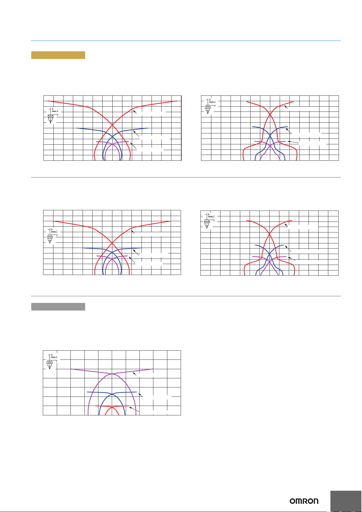
Sensing Area
PREMIUM Model
Quadruple distance model/
Spatter-resistant Quadruple distance model
Shielded
Sensing object: iron Sensing object: Aluminum
Triple distance model/
Spatter-resistant Triple distance model
Shielded
Sensing object: iron Sensing object: Aluminum
E2EW Series
BASIC Model
Single distance model/
Spatter-resistant Single distance model
Shielded
Sensing object: iron
14
Y
12
10
Distance X (mm)
8
6
4
2
0
-25 -20 -15 -10 -5 0 5 10 15 20 25
X
E2EW-(Q)X10@30
E2EW-(Q)X5@18
E2EW-(Q)X2@12
Distance Y (mm)
11
Page 12

E2EW Series
X
t
=3
mm
@
d
0
2
4
6
8
10
0102030405060708090
Side length of sensing object: d (mm)
Distance X (mm)
Stainless steel
(SUS304)
Iron
Brass
Copper
Aluminum
0
5
10
15
20
25
0 102030405060708090
100 110 120
Distance X (mm)
Side length of sensing object: d (mm)
Stainless steel
(SUS304)
Iron
Brass
Aluminum
Copper
@d
t
=3
mm
X
0
5
10
15
20
25
0 102030405060708090
100 110 120
Distance X (mm)
Side length of sensing object: d (mm)
Stainless steel
(SUS304)
Brass
Copper
Aluminum
Iron
@
d
t
=3
mm
X
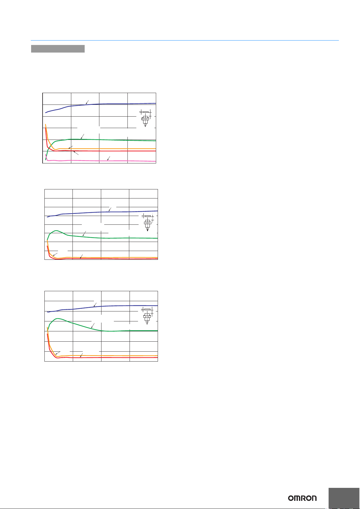
Influence of Sensing Object Size and Material
PREMIUM Model
Quadruple distance model/
Spatter-resistant Quadruple distance model
Shielded
Size: M12 E2EW-(Q)X7
Size: M18 E2EW-(Q)X12
16
14
12
Distance X (mm)
10
8
6
4
2
0
0
Stainless steel
(SUS304)
10 20 30 40 50 60 70 80 90
Size: M30 E2EW-(Q)X22
12 Size: M12 E2EW--(Q)X612
18 Size: M18 E2EW-(Q)X1018
Brass
Aluminum
Copper
Side length of sensing object: d (mm)
Iron
@
d
X
30 Size: M30 E2EW-(Q)X2030
Triple distance model/
Spatter-resistant Triple distance model
Shielded
10
8
Distance X (mm)
6
4
2
0
0 102030405060708090
14
12
10
Distance X (mm)
8
6
t
mm
=3
4
2
0
0 102030405060708090
Brass
Aluminum
Stainless steel
(SUS304)
Brass
Iron
Stainless steel
(SUS304)
Iron
Copper
@
d
t
mm
=3
X
Side length of sensing object: d (mm)
Aluminum
Copper
@
d
t
mm
=3
X
Side length of sensing object: d (mm)
12
Page 13

BASIC Model
0
10 20 30 40 50 60 70 80 90
Distance X (mm)
Side length of sensing object: d (mm)
Iron
Stainless steel
(SUS304)
Brass
Aluminum
@d
t
=3
mm
X
0
1
2
3
4
5
6
7
8
0
10 20 30 40 50 60 70 80 90
Side length of sensing object: d (mm)
Stainless steel
(SUS304)
Iron
Brass
Aluminum
@
d
t
=3
mm
X
0
2
4
6
8
10
12
14
Distance X (mm)
Single distance model/
Spatter-resistant Single distance model
Shielded
Size: M12 E2EW-(Q)X2
3
@
d
t
mm
=3
X
2
Distance X (mm)
12
Iron
E2EW Series
Brass
1
0
10 20 30 40 50 60 70 80 90
0
Stainless steel
(SUS304)
Aluminum
Size: M18 E2EW-(Q)X5
Size: M30 E2EW-(Q)X10
Copper
Side length of sensing object: d (mm)
18
30
13
Page 14

E2EW Series
0 5 10 15 20
Distance X (mm)
Iron
Brass
Aluminum
Copper
Stainless steel
(SUS304)
Thickness of sensing object: t (mm)
t
X
Sensing object size:
36 × 36 mm
0
2
4
6
8
10
12
14
16
0 5 10 15 20
Stainless steel
(SUS304)
Iron
Aluminum
Copper
Brass
Distance X (mm
Thickness of sensing object: t (mm)
t
X
Sensing object size:
30 × 30 mm
0
2
4
6
8
10
12
14
16
0 5 10 15 20
Distance X (mm)
Brass
Iron
Aluminum
Copper
Stainless steel
(SUS304)
Thickness of sensing object: t (mm)
t
X
Sensing object size:
60 × 60 mm
0
5
10
15
20
25
30
Influence of Sensing Object Thickness and Material
PREMIUM Model
Quadruple distance model/
Spatter-resistant Quadruple distance model
Shielded
Size: M12 E2EW-(Q)X7
10
Aluminum
8
Distance X (mm)
6
Iron
4
Stainless steel
(SUS304)
2
0
0 1 2 3 4 5 6 7 8 9 10 11 12 13 14 15
Size: M18 E2EW-(Q)X12
12 Size: M12 E2EW-(Q)X612
Brass
Copper
t
Sensing object size:
21 × 21 mm
Thickness of sensing object: t (mm)
18 Size: M18 E2EW-(Q)X1018
Triple distance model/
Spatter-resistant Triple distance model
Shielded
10
8
Distance X (mm)
6
X
4
2
0 1 2 3 4 5 6 7 8 9 10 11 12 13 14 15
Aluminum
Copper
Stainless steel
(SUS304)
Iron
Brass
Sensing object size:
18 × 18 mm
Thickness of sensing object: t (mm)
t
X
Size: M30 E2EW-(Q)X22
30
25
Distance X (mm)
20
15
10
5
0
0 5 10 15 20
Brass
Iron
Stainless steel
(SUS304)
30 Size: M30 E2EW-(Q)X2030
Aluminum
Copper
Thickness of sensing object: t (mm)
14
t
Sensing object size:
66 × 66 mm
X
Page 15
BASIC Model
0 5 10 15 20
Distance X (mm)
Iron
Brass
Aluminum
Stainless steel
(SUS304)
Copper
Thickness of sensing object: t (mm)
t
X
Sensing object size:
12 × 12 mm
0
1
2
3
t
X
Sensing object size: 18 × 18 mm
0 5 10 15 20
Distance X (mm)
Iron
Stainless steel
(SUS304)
Aluminum
Brass
Thickness of sensing object: t (mm)
0
4
3
2
1
5
6
7
8
0 5 10 15 20
Aluminum
Brass
Distance X (mm)
Stainless steel
(SUS304)
Iron
Thickness of sensing object: t (mm)
t
X
Sensing object size: 30 × 30 mm
0
2
4
6
8
10
12
14
Single distance model/
Spatter-resistant Single distance model
Shielded
Size: M12 E2EW-(Q)X2
12
E2EW Series
Size: M18 E2EW-(Q)X5
Size: M30 E2EW-(Q)X10
18
30
15
Page 16

E2EW Series
0
50
100
150
200
250
300
0 10
246
8
X
t=3 mm
Aluminum
Iron
Distance X (mm)
Detection level
Stainless steel
(SUS304)
@d
=21 mm
0
50
100
150
200
250
300
0
10
246
8
X
t=3 mm
Aluminum
Iron
Distance X (mm)
Detection level
Stainless steel
(SUS304)
@d
=18 mm
X
t=3 mm
0
50
100
150
200
250
300
0 5 10 15
@d=36 mm
Aluminum
Stainless steel
(SUS304)
Distance X (mm)
Detection level
Iron
X
t=3 mm
0
50
100
150
200
250
300
0 5 10 15
@d=30 mm
Aluminum
Stainless steel
(SUS304)
Distance X (mm)
Detection level
Iron
X
t=3 mm
0 5 10 15 20 25 30
0
50
100
150
200
250
300
Aluminum
Iron
Stainless steel
(SUS304)
Distance X (mm)
Detection level
@d=66 mm
X
t=3 mm
0 5 10 15 20 25 30
0
50
100
150
200
250
300
@d=60 mm
Aluminum
Stainless steel
(SUS304)
Distance X (mm)
Detection level
Iron
Monitor Output vs. Sensing Distance
PREMIUM Model
Quadruple distance model/
Spatter-resistant Quadruple distance model
Shielded
Size: M12 E2EW-(Q)X7
Size: M18 E2EW-(Q)X12
12 Size: M12 E2EW-(Q)X612
18 Size: M18 E2EW-(Q)X1018
Triple distance model/
Spatter-resistant Triple distance model
Shielded
Size: M30 E2EW-(Q)X22
30 Size: M30 E2EW-(Q)X2030
16
Page 17

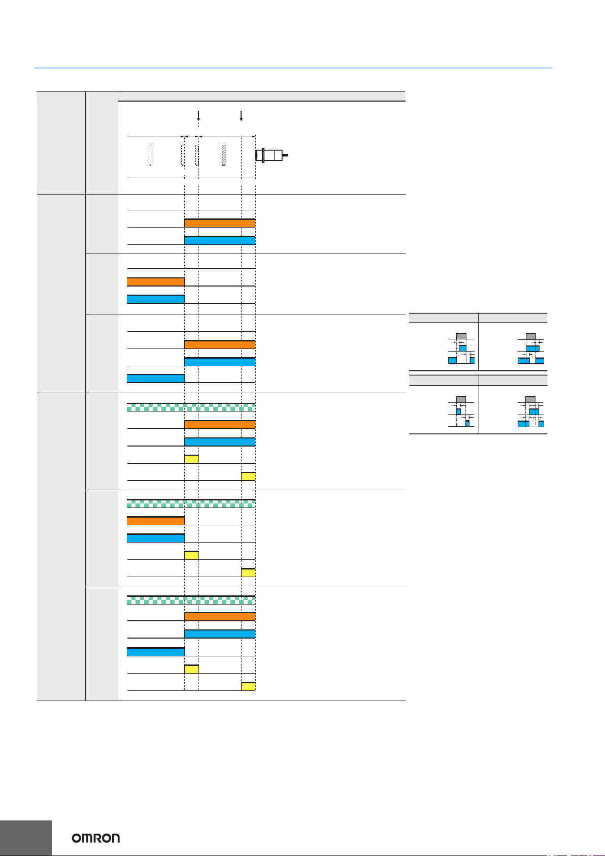
I/O Circuit Diagrams/Timing charts
OUT
0V
+V
DC10 to 30V
Brown (1)
Black (4)
Blue (3)
Load
Proximity
sensor
main
circuit
OUT
0V
+V
Proximity
sensor
main
circuit
Brown (1)
Black (2)
Blue (3)
Load
DC10 to 30V
OUT1
0V
+V
OUT2
Proximity
sensor
main
circuit
Load
Load
Brown (1)
Black (4)
Blue (3)
White (2)
DC10 to 30V
1
4
2
3
DC 3-wire
PNP output
Operation
mode
PREMIUM Model
Model
Standard I/O mode (SIO mode)
When using as a general
Output circuit
IO-Link Communication mode (COM mode)
When using the Sensor connected to
E2EW Series
IO-Link Master Unit
+V
Brown (1)
IO-Link master
+V (1)
Proximity
NO E2EW-(Q)XB1
sensor
main
circuit
NC E2EW-(Q)XB2 ---
NO+NC E2EW-(Q)XB3
Proximity
sensor
main
circuit
C/Q
Black (4)
0V
Blue (3)
+V
Brown (1)
C/Q
Black (4)
DO
White (2)
0V
Blue (3)
C/Q (4)
0V (3)
IO-Link master
+V (1)
C/Q (4)
DI (2)
0V (3)
0V
Connector Pin Arrangement
M12 Connector
M12 Smartclick Connector
In the IO-Link mode, the cord between the IO-Link master
and sensor must have a length of 20 m or less.
17
Page 18
E2EW Series
Sensing
object
(%)
100 080 20
Nonsensing
area
Unstable
Sensing
area
Rated Sensing distance
Stable
Sensing area
Set position
ProximitySensor
Excessive proximity judgment distance
Flashing
(1sec cycle)
Flashing
(1sec cycle)
Flashing
(1sec cycle)
Output mode
Standard
I/O mode
(SIO mode)
NO+NC
NO
NC
NO
Operation
mode
Comunication indicator (green) : Always OFF
Operation indicator (orange)
ON
ON
OFF
ON
OFF
OFF
Control output
Comunication indicator (green) : Always OFF
Operation indicator (orange)
ON
OFF
ON
OFF
ON
OFF
ON
OFF
ON
OFF
ON
OFF
ON
OFF
ON
OFF
ON
OFF
Control output
Comunication indicator (green) : Always OFF
Operation indicator (orange)
Comunication indicator (green)
Operation indicator (orange)
Comunication indicator (green)
Operation indicator (orange)
Comunication indicator (green)
Operation indicator (orange)
Control output 1
Control output 2
1
0
1
0
1
0
1
0
1
0
1
0
1
0
Control output1 (PD1_bit0)
1
0
1
0
Excessive proximity detection (PD1_bit5)
Control output (PD1_bit0)
Instability detection (PD1_bit4)
Excessive proximity detection (PD1_bit5)
Control output (PD1_bit0)
Instability detection (PD1_bit4)
Excessive proximity detection (PD1_bit5)
Instability detection (PD1_bit4)
1
0
NC
NO+NC
ON
OFF
IO-Link
Communication
mode
(COM mode)
Control output2 (PD1_bit1)
Timing chart
T
T
1
0
1
0
NO
NC
ON
OFF
ON
OFF
Present
Not
present
Sensing
object
T
T
NO
NC
ON
OFF
ON
OFF
1
0
1
0
Present
Not
present
Sensing
object
PNP output
3. The timer function of the control
output can be set up by the IO-Link
communications. (It is able to select
ON delay, OFF delay, one-shot, or
ONOFF delay function and select a
timer time of 1 to 16,383ms (T).)
ON delay OFF delay
One shot ONOFF delay
Present
Sensing
Not
object
present
ON
1
NO
OFF
0
ON
1
NC
OFF
0
4. The excessive proximity diagnosis
function can be selected by the IOLink communications.
5. The instability detection diagnosis
can be selected by the IO-Link
communications.
6. The judgment time for the instability
detection diagnosis can be selected
by the IO-Link communications.
(For the ON delay timer function, the
setting can be selected from 0
(invalid), 10, 50, 100, 300, 500, or
1000 ms.)
7. The judgment distance of the
excessive proximity diagnosis
function can be selected by the IOLink communications.
(The distance can be selected as a
combination of the material of the
object detected, such as iron,
aluminum, or SUS and the judgment
distance of approximately 10, 20, or
30%. However, it is not allowed to
Please contact your OMRON sales representative regarding assignment of data.
1. For models with IO-Link, the operation mode can be changed by the IO-Link communications.
2. If using a model with IO-Link as a general sensor or using a model without IO-Link, it operates in the standard I/O mode (SIO mode).
select a combination of aluminum
and 10%.)
Please contact your OMRON sales
representative regarding the IO-Link
setup file (IODD file).
Present
Sensing
Not
object
T
T
present
ON
NO
OFF
ON
NC
OFF
T
T
1
0
TT
1
0
18
Page 19

DC 3-wire
Sensing
object
(%)
100 0
Nonsensing
area
Rated Sensing distance
Stable
sensing area
ProximitySensor
Operation indicator
(orange)
ON
OFF
ON
OFF
Control output
Sensing
object
(%)
100 0
Nonsensing
area
Rated Sensing distance
Stable
sensing area
ProximitySensor
ON
OFF
Control output
ON
OFF
Operation indicator
(orange)
OUT1
OUT2
0V
Load
Load
Brown (1)
Black (4)
DC10 to 30V
+V
Blue (3)
Proximity
sensor
main
circuit
White (2)
1
4
2
3
PNP output
Operation
mode
E2EW Series
BASIC Model
Model Timing chart Output circuit
DC10 to 30V
Brown (1)
+V
NO E2EW-(Q)XB1
NC E2EW-(Q)XB2
NO+NC E2EW-(Q)XB3
Sensing
object
(%)
Nonsensing
area
sensing area
Rated Sensing distance
100 0
Stable
ProximitySensor
Proximity
sensor
main
circuit
Proximity
sensor
main
circuit
Black (4)
Blue (3)
DC10 to 30V
Brown (1)
Black (2)
Blue (3)
OUT
Load
0V
+V
OUT
Load
0V
Connector Pin Arrangement
M12 Connector
M12 Smartclick Connector
ON
Operation indicator
(orange)
OFF
ON
Control output 1
OFF
ON
Control output 2
OFF
19
Page 20

E2EW Series
OUT
0V
Proximity
sensor
main
circuit
Brown (1)
Black (4)
Blue (3)
Load
DC10 to 30V
+V
100 0
Nonsensing
area
Stable
sensing area
Sensing
object
(%)
Rated Sensing distance
ProximitySensor
Operation indicator
(orange)
Control output
ON
OFF
ON
OFF
OUT
0V
Proximity
sensor
main
circuit
Brown (1)
Black (2)
Blue (3)
+V
DC10 to 30V
Load
100 0
ON
OFF
ON
OFF
ON
OFF
Nonsensing
area
Stable
sensing area
Sensing
object
Rated Sensing distance
ProximitySensor
Operation indicator
(orange)
Control output 1
Control output 2
(%)
1
4
2
3
DC 3-wire
NPN OUTPUT
Operation
mode
PREMIUM Model
Model Timing chart Output circuit
NO E2EW-(Q)XC1
NC E2EW-(Q)XC2
NO+NC E2EW-(Q)XC3
Nonsensing
area
Sensing
object
Rated Sensing distance
(%)
Stable
sensing area
100 0
ProximitySensor
Operation indicator
ON
(orange)
OFF
ON
Control output
OFF
Proximity
sensor
main
circuit
Brown (1)
Black (4)
White (2)
DC10 to 30V
+V
LoadLoad
OUT1
OUT2
20
Connector Pin Arrangement
M12 Connector
M12 Smartclick Connector
Blue (3)
0V
Page 21

DC 3-wire
Sensing
object
(%)
100 0
Nonsensing
area
Rated Sensing distance
Stable
sensing area
ProximitySensor
ON
OFF
ON
OFF
Operation indicator
(orange)
Control output
OUT
0V
Brown (1)
Black (4)
Blue (3)
Load
DC10 to 30V
+V
Proximity
sensor
main
circuit
OUT
0V
Brown (1)
Black (2)
Blue (3)
Load
DC10 to 30V
+V
Proximity
sensor
main
circuit
Sensing
object
(%)
100 0
Nonsensing
area
Rated Sensing distance
Stable
sensing area
ProximitySensor
ON
OFF
ON
OFF
ON
OFF
Operation indicator
(orange)
Control output 1
Control output 2
1
4
2
3
NPN OUTPUT
Operation
mode
NO E2EW-(Q)XC1
E2EW Series
BASIC Model
Model Timing chart Output circuit
NC E2EW-(Q)XC2
NO+NC E2EW-(Q)XC3
Nonsensing
Sensing
object
(%)
area
sensing area
Rated Sensing distance
100 0
Stable
ProximitySensor
ON
Operation indicator
(orange)
OFF
ON
Control output
OFF
Proximity
sensor
main
circuit
Brown (1)
Load
Black (4)
OUT1
White (2)
Blue (3)
DC10 to 30V
+V
Load
OUT2
0V
Connector Pin Arrangement
M12 Connector
M12 Smartclick Connector
21
Page 22

E2EW Series
1
2
3
4
1
2
3
4
Brown (+)
White (not connected)
Blue (–)
Black (Output)
XS2
E2EW Series
Main
circuit
1
2
3
4
1
2
3
4
Brown (+)
White (not connected)
Blue (-)
Black (Output)
XS2
E2EW Series
Main
circuit
1
2
3
4
1
2
3
4
Brown (+)
White (Output)
Blue (-)
Black (not connected)
XS2
E2EW Series
Main
circuit
Connections for Sensor I/O Connectors
DC 3-Wire
Proximity Sensor Sensor I/O Connectors
Types Output
Operation
mode
Model Model Connections
1
DC 3-Wire
(M12 Connector)
PNP
NPN
NO E2EW-(Q)X
NC E2EW-(Q)X
NO+NC E2EW-(Q)X
NO E2EW-(Q)X
NC E2EW-(Q)X
NO+NC E2EW-(Q)X
B1- M1TJ/M1
B2-M1TJ/M1
B3-M1TJ/M1
C1-M1TJ/M1
C2-M1TJ/M1
C3-M1TJ/M1
XS2F-
4M
M12
XS2W-D42
-81-F
E2EW Series
Main
circuit
E2EW Series
Main
circuit
E2EW Series
Main
circuit
XS2
1
1
2
2
3
3
4
4
XS2
1
1
2
2
3
3
4
4
XS2
1
1
2
2
3
3
4
4
Brown (+)
White (Output)
Blue (-)
Black (not connected)
Brown (+)
White (Output 2)
Blue (-)
Black (Output 1)
Brown (+)
White (Output 2)
Blue (-)
Black (Output 1)
1. If the XS2W Series Connector which has a socket and plug on the cable ends is connected to the Sensor, this part will be a plug.
2. Different from Proximity Sensor wire colors.
22
Page 23

E2EW Series
WARNING
Safety Precautions
Be sure to read the precautions for all models in the website at: http://www.automation.omron.com/.
Warning Indications
Warning level
Indicates a potentially hazardous situation
which, if not avoided, will result in minor or
moderate injury, or may result in serious
injury or death. Additionally there may be
significant property damage.
Precautions
for Safe Use
Precautions
for Correct
Use
Supplementary comments on what to do or
avoid doing, to use the product safely.
Supplementary comments on what to do or
avoid doing, to prevent failure to operate,
malfunction or undesirable effect on product
performance.
Meaning of Product Safety Symbols
General prohibition
Indicates the instructions of unspecified
prohibited action.
Caution, explosion
Indicates the possibility of explosion under
specific conditions.
WARNING
This product is not designed or rated for ensuring
safety of persons either directly or indirectly.
Do not use it for such purposes.
Otherwise, explosion may result.
Never use the product with an AC power supply.
Do not use the product in any atmosphere or environment that
exceeds the ratings.
Operating Environment
1. Do not install the Sensor in the following locations.
(1) Outdoor locations directly subject to sunlight, rain, snow,
(2) Locations subject to atmospheres with chemical vapors,
(3) Locations subject to corrosive gases.
2. The Sensor may malfunction if used near ultrasonic cleaning
equipment, high-frequency equipment, transceivers, cellular
phones, inverters, or other devices that generate a high-frequency
electric field. Please refer to the Precautions for Correct Use on
the OMRON website (www.ia.omron.com) for typical measures.
3. Laying the Proximity Sensor wiring in the same conduit or duct as
high-voltage wires or power lines may result in incorrect operation
and damage due to induction. Wire the Sensor using a separate
conduit or independent conduit.
4. Never use thinner or other solvents. Otherwise, the Sensor
surface may be dissolved.
5. When turning on the power by influence of temperature
environment, an outputmis-pulse sometimes occurs. After the
sensor has passed for 300 msec after turning on, please use in the
stable state.
6. The sensor is adjusted with a high degree of accuracy, so do not
use in the environment with sudden temperature change.
7. Operation check is performed using an OMRON's IO-Link master.
If using an IO-Link master from another company, perform the
operation check in advance.
8. When connecting non IO-Link compliant models to the IO-Link
master, use the SIO mode.
9. In the IO-Link mode, the cord between the IO-Link master and
sensor must have a length of 20 m or less.
10.The Sensor cannot be used embedded in where pressure is
constantly applied to the sensing surface, such as hydraulic
cylinders and hydraulic valves.
Precautions for Correct Use
waterdroplets, or oil.
inparticular solvents and acids.
Precautions for Safe Use
The following precautions must be observed to ensure safe operation.
1. Do not use the product in environments subject to flammable or
explosive gases.
2. Do not attempt to disassemble, repair, or modify the product.
3. Do not use a voltage that exceeds the rated operating voltage
range.
Applying a voltage that is higher than the operating voltage range
may result in explosion or fire.
4. Be sure that the power supply polarity and other wiring is correct.
Incorrect wiring may cause explosion or fire.
5. If the power supply is connected directly without a load, the
internal elements may explode or burn.
6. Dispose of the product according to applicable regulations (laws).
23
Page 24

E2EW Series
Design
Influence of Surrounding Metal
When mounting the Proximity Sensor, ensure that the minimum
distances given in the following table are maintained.
If you use a nut, only use the provided nut. And ensure that the
minimum distances between the sensing surface and nut is bigger
than the "L" given in the following table.
Other non-ferrous metals affect sensor's performance in the same
way as aluminum. Perform the operation check in advance.
d dia.
*1
Mounting panel material: Iron
Models Model L d D m n
Quadruple
distance model
Triple distance
model
Single distance
model
E2EW-(Q)X712 4 30 4 28 36
E2EW-(Q)X1218 6 54 6 36 54
E2EW-(Q)X2230 8 90 8 66 90
E2EW-(Q)X612 4 30 4 24 36
E2EW-(Q)X1018 2 54 2 30 54
E2EW-(Q)X2030 0 30 0 60 90
E2EW-(Q)X212 0 12 0 8 40
E2EW-(Q)X518 0 18 0 20 60
E2EW-(Q)X1030 0 30 0 40 100
Mounting panel material: Aluminum
Models Model L d D m n
Quadruple
distance model
Triple distance
model
Single distance
model
1. If you use the model E2EW-(Q)X2230, or E2EW-(Q)X2030,
the panel thickness (t) is 3 mm or less.
E2EW-(Q)X712 12 70 12 28 70
E2EW-(Q)X1218 12 80 12 36 80
E2EW-(Q)X2230 16 120 16 66 120
E2EW-(Q)X612 12 70 12 24 70
E2EW-(Q)X1018 12 80 12 30 80
E2EW-(Q)X2030 16 120 16 60 120
E2EW-(Q)X212 12 70 12 8 70
E2EW-(Q)X518 12 80 12 20 80
E2EW-(Q)X1030 16 120 16 40 120
(Unit: mm)
When the Proximity Sensor is mounted in metal, ensure that the
minimum distances given in the following table are maintained.
d dia.
(Unit: mm)
Embedded material: Iron
Models Model l d D m n
Quadruple
distance model
Triple distance
model
Single distance
model
E2EW-(Q)X712 4 3 0 4 28 36
E2EW-(Q)X1218 6 54 6 36 54
E2EW-(Q)X2230 8 90 8 66 90
E2EW-(Q)X612 0 212 20 224 36
E2EW-(Q)X1018 0 18 0 30 54
E2EW-(Q)X2030 0 30 0 60 90
E2EW-(Q)X212 0 1 2 0 8 40
E2EW-(Q)X518 0 1 8 0 20 60
E2EW-(Q)X1030 0 30 0 40 100
*2. If the thickness of the mounting bracket (t) is less than 10 mm, be
sure to install the Sensor so that l 2, d (dia.) 30, and D 2.
Embedded material: Aluminum
Models Model l d D m n
Quadruple
distance model
Triple distance
model
Single distance
model
E2EW-(Q)X712 12 70 12 28 70
E2EW-(Q)X1218 12 80 12 36 80
E2EW-(Q)X2230 16 120 16 66 120
E2EW-(Q)X612 12 70 12 24 70
E2EW-(Q)X1018 12 80 12 30 80
E2EW-(Q)X2030 16 120 16 60 120
E2EW-(Q)X212 12 70 12 8 70
E2EW-(Q)X518 12 80 12 20 80
E2EW-(Q)X1030 16 120 16 40 120
24
Page 25

E2EW Series
A
B
A
d
D
Detection
surface
Cutting
chips
Cutting
chips
Pressed down
Tr
Mutual Interference
When installing two or more Proximity Sensors face-to-face or sidebyside, ensure that the minimum distances given in the following
table are maintained.
(Unit: mm)
Models Model
Quadruple
distance model
Triple distance
model
Single distance
model
E2EW-(Q)X712 45 40
E2EW-(Q)X1218 80 60
E2EW-(Q)X2230 135 110
E2EW-(Q)X612 45 40
E2EW-(Q)X1018 80 60
E2EW-(Q)X2030 135 110
E2EW-(Q)X212 40 35
E2EW-(Q)X518 65 60
E2EW-(Q)X1030 110 100
Chips from Cutting Aluminum
Normally, chips from cutting aluminum will not cause a detection
signal to be output even if it adheres to or accumulates on the
detection surface. In the following cases, however, a detection signal
may be output.
Remove the cutting chips in these cases.
1. If d ≥ 2/3D at the center of the detection
surface where d is the cutting chip size and D is
the detection surface size
Model Dimension
E2EW-(Q)X12 10
E2EW-(Q)X18 16
E2EW-(Q)X30 28
(Unit: mm)
D
Item
A B
Mounting
Tightening Force
Do not tighten the nut with excessive force.
A washer must be used with the nut.
The tightening force must be the same or less than the figures in the
following table.
Quadruple distance model, Triple distance model
(Unit: N·m)
Size
M12 20 (15)
M18 70 (35)
M30 180 (60)
* Tighten the nut of the E2EW-Q to a torque in parentheses.
Single distance model
Size
M12 30 (15)
M18 70 (35)
M30 180 (60)
* Tighten the nut of the E2EW-Q to a torque in parentheses.
Note: When mounting the Proximity Sensor, only use the provided
nut. Do not use set screws. The Sensor may malfunction.
Torque
(Unit: N·m)
Torque
2.If the cutting chips are pressed down
25
Page 26
E2EW Series
F
Dimensions
Sensors
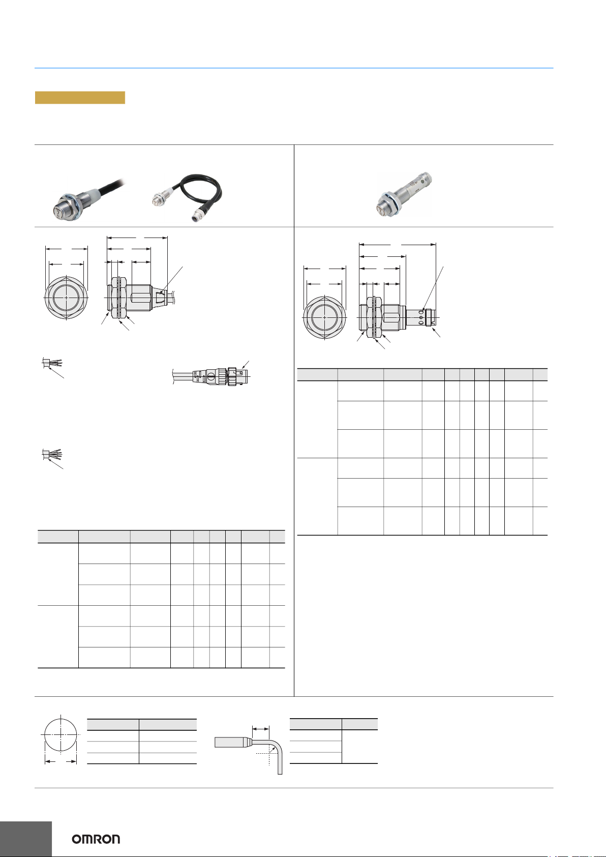
PREMIUM Model
Pre-wired Model/
Pre-wired Connector Model
F
G
A
Pre-wired Model Pre-wired Connector Model (M1TJ)
(Operation mode):
Output configuration (B1, C1): NO
Vinyl-insulated round cable with
3 conductors size: 6-dia.
(Conductor cross section: 0.3 mm
Insulator diameter: 1.05 mm),
Standard length: 2 m
(Operation mode):
Output configuration (B3, C3): NO+NC
Vinyl-insulated round cable with
4 conductors size: 6-dia.
(Conductor cross section: 0.3 mm
Insulator diameter: 1.05 mm),
Standard length: 2 m
Models Model A B C D E F G
Quadruple
distance
model
Triple
distance
model
(B2, C2): NC
E2EW-(Q)X7
12(-M1TJ)
E2EW-(Q)X12
18(-M1TJ)
E2EW-(Q)X22
30(-M1TJ)
E2EW-(Q)X6
12(-M1TJ)
E2EW-(Q)X10
18(-M1TJ)
E2EW-(Q)X20
30(-M1TJ)
E2EW/E2EW-Q Series
(Quadruple distance/Triple distance/Spatter-resistant Quadruple distance,
Spatter-resistant Triple distance model)
B
C
DE
Two clamping nuts
Toothed washer
2
(AWG24),
2
(AWG24),
M12P1 41.5 30 4 10 21 dia. 17
M18P1 41.5 30 4 13 29 dia. 24
M30P1.5
M12P1 41.5 30 4 10 21 dia. 17
M18P1 41.5 30 4 13 29 dia. 24
M30P1.5
Indicators
Standard I/O mode (SIO mode):
Operation indicator (orange/ON),
communication indicator (green/OFF)
IO-Link Communication mode
(COM mode):
Operation indicator (orange/ON),
comunication indicator
(green/Flashing (1sec cycle)*
* Models with IO-Link only.
M12×P1
(Operation mode):
Output configuration (B1, C1): NO
Vinyl-insulated round cable with
3 conductors size: 6-dia.
(Conductor cross section: 0.3 mm
Insulator diameter: 1.05 mm),
Standard length:0.3 m
(Operation mode):
Output configuration (B3, C3): NO+NC
Vinyl-insulated round cable with
4 conductors size: 6-dia.
(Conductor cross section: 0.3 mm
Insulator diameter: 1.05 mm),
Standard length: 0.3 m
(B2, C2): NC
41.5 30 5 13 42 dia. 36
41.5 30 5 13 42 dia. 36
2
(AWG24),
2
(AWG24),
Tolerance class IT16 applies to dimensions in this data sheet unless otherwise specified.
(Unit: mm)
M12 Connector Model
B
C
A
E
D
F
Toothed washer
Two clamping nuts
G
H
Models Model A B C D E F G H
Quadruple
distance
model
E2EW-(Q)
12-M1
X7
E2EW-(Q)
18-
X12
M1
E2EW-(Q)
30-
X22
M12P1 54.4 --- 4 28 8 21 dia. 17
M18P1 54.4 32 4 28 11 29 dia. 24
M30P1.5
M1
Triple
distance
model
E2EW-(Q)
12-M1
X6
E2EW-(Q)
18-
X10
M1
E2EW-(Q)
30-
X20
M12P1 54.4 --- 4 28 8 21 dia. 17
M18P1 54.4 32 4 28 11 29 dia. 24
M30P1.5
M1
Indicators
Standard I/O mode (SIO mode):
Operation indicator (orange/ON),
communication indicator (green/OFF)
IO-Link Communication mode
(COM mode):
Operation indicator (orange/ON),
comunication indicator
(green/Flashing (1sec cycle)*
* Models with IO-Link only.
M12×P1
54.4 32 5 28 11 42 dia. 36
54.4 32 5 28 11 42 dia. 36
Mounting Hole Dimensions
Dimensions F (mm)
26
M12 12.5 dia.
M18 18.5 dia.
M30 30.5 dia.
Angle R of the Bending Wire
10 mm
+0.5
0
+0.5
0
+0.5
0
R
Dimensions R (mm)
M12
18M18
M30
Page 27
E2EW Series
F
+0.5
0
+0.5
0
+0.5
0
10 mm
R
Dimensions
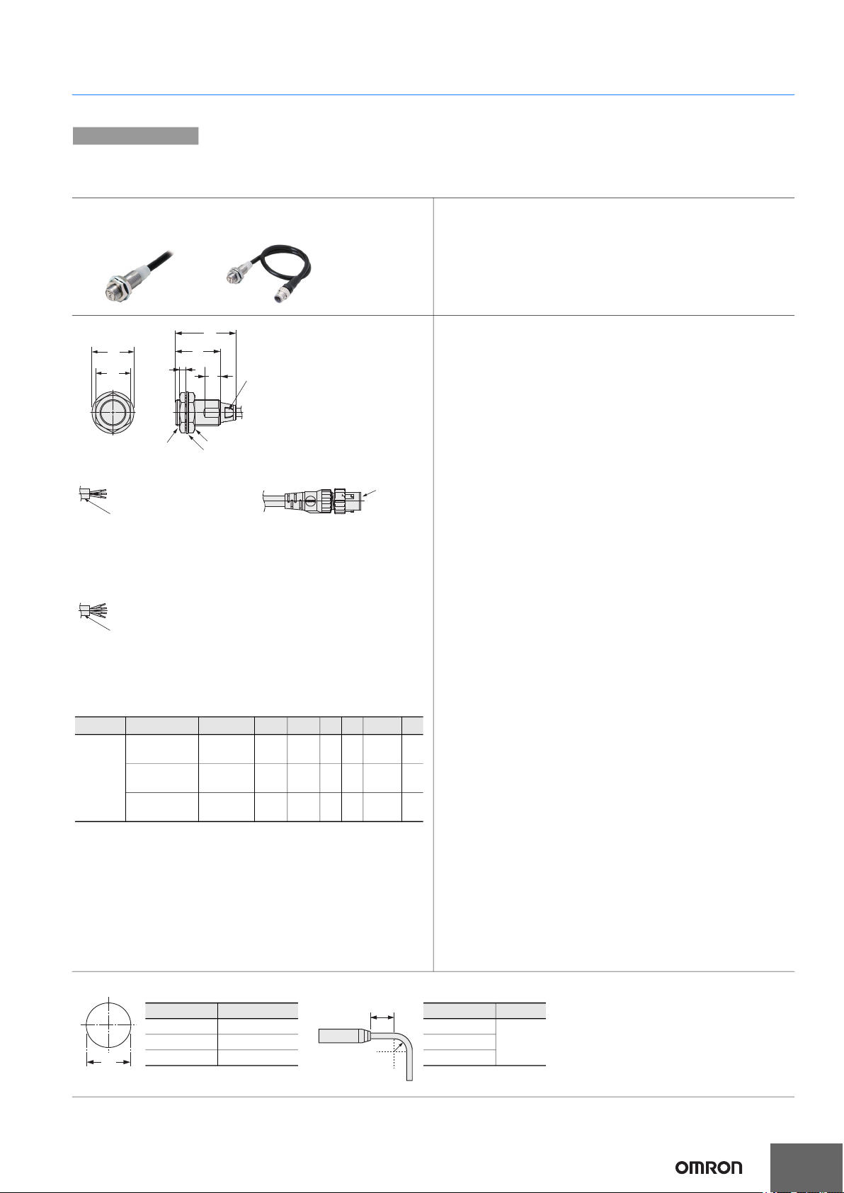
Sensors
BASIC Model
Pre-wired Model/
Pre-wired Connector Model
F
G
Pre-wired Model
(Operation mode):
Output configuration (B1, C1): NO
Vinyl-insulated round cable with
3 conductors size: 6-dia.
(Conductor cross section:
2
(AWG24),
0.3 mm
Insulator diameter: 1.05 mm),
Standard length: 2 m
(Operation mode):
Output configuration (B3, C3):
NO+NC
Vinyl-insulated round cable with
4 conductors size: 6-dia.
(Conductor cross section:
2
(AWG24),
0.3 mm
Insulator diameter: 1.05 mm),
Standard length: 2 m
E2EW/E2EW-Q Series
(Single distance model/Spatter-resistant Single distance model)
B
C
D
E
A
Two clamping nuts
Toothed washer
(B2, C2): NC
Operation indicator
(orange)
Pre-wired Connector Model (M1TJ)
(Operation mode):
Output configuration (B1, C1): NO
Vinyl-insulated round cable with
3 conductors size: 6-dia.
(Conductor cross section:
0.3 mm2 (AWG24),
Insulator diameter: 1.05 mm),
Standard length: 0.3 m
(Operation mode):
Output configuration (B3, C3): NO+NC
Vinyl-insulated round cable
with 4 conductors size: 6-dia.
(Conductor cross section:
2
0.3 mm
(AWG24),
Insulator diameter: 1.05 mm),
Standard length: 0.3 m
(B2, C2): NC
M12×P1
Tolerance class IT16 applies to dimensions in this data sheet unless otherwise specified.
(Unit: mm)
Models Model A B C D E F G
E2EW-(Q)X2
Single
distance
model
12(-M1TJ)
E2EW-(Q)X5
18(-M1TJ)
E2EW-(Q)X10
30(-M1TJ)
Mounting Hole Dimensions
M12P1 41.9 30.4 4 7 21 dia. 17
M18P1 41.9 30.4 4 10 29 dia. 24
M30P1.5 41.9 30.3 5 10 42 dia. 36
Angle R of the Bending Wire
Dimensions F (mm)
M12 12.5 dia.
M18 18.5 dia.
M30 30.5 dia.
Dimensions R (mm)
M12
18M18
M30
27
Page 28

Printed on recycled paper.
OMRON AUTOMATION AMERICAS HEADQUARTERS • Chicago, IL USA • 847.843.7900 • 800.556.6766 • automation.omron.com
OMRON CANADA, INC. • HEAD OFFICE
Toronto, ON, Canada • 416.286.6465 • 866.986.6766 • automation.omron.com
OMRON ELECTRONICS DE MEXICO • HEAD OFFICE
Ciudad de México • 52.55.5901.4300
OMRON ELECTRONICS DE MEXICO • SALES OFFICE
San Pedro Garza García, N.L. • 81.12.53.7392 • 01.800.386.6766 • mela@omron.
com
OMRON ELECTRONICS DE MEXICO • SALES OFFICE
Eugenio Garza Sada,León, Gto • 01.800.386.6766 • mela@omron.com
• 01.800.386.6766 • mela@omron.com
Authorized Distributor:
OMRON ELETRÔNICA DO BRASIL LTDA • HEAD OFFICE
São Paulo, SP, Brasil • 55 11 5171-8920 • automation.omron.com
OMRON ARGENTINA • SALES OFFICE
Buenos Aires, Argentina
mela@omron.com
OTHER OMRON LATIN AMERICA SALES
+54.11.4521.8630 • +54.11.4523.8483 • mela@omron.com
• +54.11.4521.8630 • +54.11.4523.8483
Controllers & I/O
• Machine Automation Controllers (MAC) • Motion Controllers
• Programmable Logic Controllers (PLC) • Temperature Controllers • Remote I/O
Robotics
• Industrial Robots • Mobile Robots
Operator Interfaces
• Human Machine Interface (HMI)
Motion & Drives
• Machine Automation Controllers (MAC) • Motion Controllers • Servo Systems
requency Inverters
• F
Vision, Measurement & Identification
• Vision Sensors & Systems • Measurement Sensors • Auto Identification
Systems
Sensing
• Photoelectric Sensors • Fiber-Optic Sensors • Proximity Sensors
otary Encoders • Ultrasonic Sensors
• R
Safety
• Safety Light Curtains • Safety Laser Scanners • Programmable Safety Systems
• Safety Mats and Edges • Safety Door Switches • Emergency Stop Devices
• Safety Switches & Operator Controls • Safety Monitoring/Force-guided Relays
Control Components
• Power Supplies • Timers • Counters • Programmable Relays
• Digital Panel Meters • Monitoring Products
Switches & Relays
• Limit Switches • Pushbutton Switches • Electromechanical Relays
olid State Relays
• S
Software
• Programming & Configuration • Runtime
D122DI-E3-02
Note: Specifications are subject to change.
© 2021 Omron. All Rights Reserved.
Printed in U.S.A.
 Loading...