

查询E2EL-1R5E12M供应商
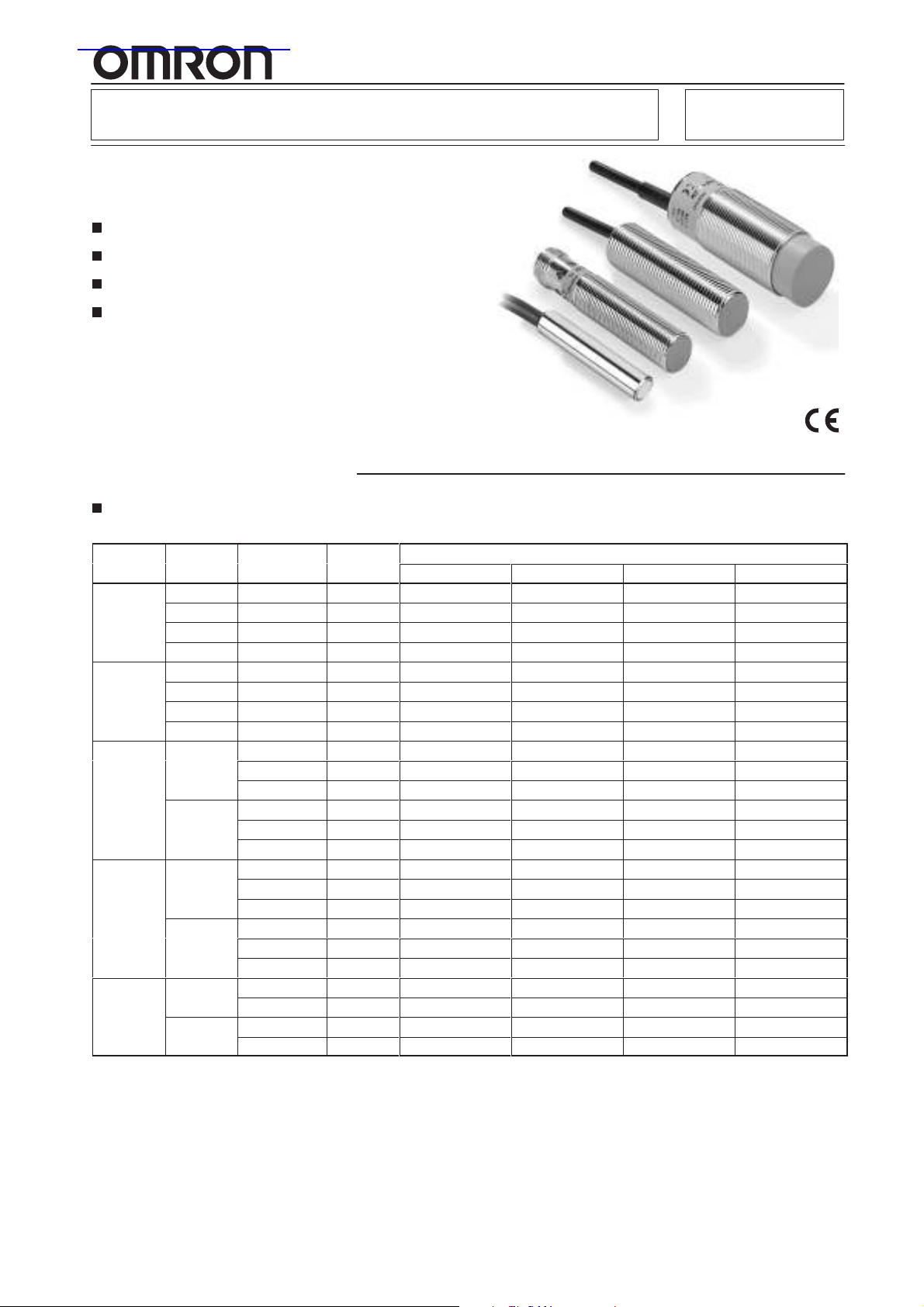
Cylindrical Proximity Sensor E2EL
A new series of easy–to–use models for
standard– and double–distance
Stainless steel and brass housing
Two housing length for each type
Pre–wired and Plug–in connector types
Short–circuit protection and reverse pola-
rity protection
Ordering Information
Cable types
Brass housing
Diameter Length Mounting Sensing
∅6,5
M8 30 mm Shielded 1,5 mm E2EL–X1R5E1 2M E2EL–X1R5E2 2M E2EL–X1R5F1 2M E2EL–X1R5F2 2M
M12 41 mm Shielded 2,0 mm E2EL–X2E1 2M E2EL–X2E2 2M E2EL–X2F1 2M E2EL–X2F2 2M
M18 40 mm Shielded 5,0 mm E2EL–X5E1 2M E2EL–X5E2 2M E2EL–X5F1 2M E2EL–X5F2 2M
M30 40 mm Shielded 10,0 mm E2EL–X10E1 2M E2EL–X10E2 2M E2EL–X10F1 2M E2EL–X10F2 2M
30 mm Shielded 1,5 mm E2EL–C1R5E1 2M E2EL–C1R5E2 2M E2EL–C1R5F1 2M E2EL–C1R5F2 2M
32 mm Non–shielded 2,0 mm E2EL–C2ME1 2M E2EL–C2ME2 2M E2EL–C2MF1 2M E2EL–C2MF2 2M
45 mm Shielded 1,5 mm E2EL–C1R5E1–L 2M E2EL–C1R5E2–L 2M E2EL–C1R5F1–L 2M E2EL–C1R5F2–L 2M
47 mm Non–shielded 2,0 mm E2EL–C2ME1–L 2M E2EL–C2ME2–L 2M E2EL–C2MF1–L 2M E2EL–C2MF2–L 2M
32 mm Non–shielded 2,0 mm E2EL–X2ME1 2M E2EL–X2ME2 2M E2EL–X2MF1 2M E2EL–X2MF2 2M
45 mm Shielded 1,5 mm E2EL–X1R5E1–L 2M E2EL–X1R5E2–L 2M E2EL–X1R5F1–L 2M E2EL–X1R5F2–L 2M
47 mm Non–shielded 2,0 mm E2EL–X2ME1–L 2M E2EL–X2ME2–L 2M E2EL–X2MF1–L 2M E2EL–X2MF2–L 2M
Shielded 4,0 mm E2EL–X4E1–D 2M E2EL–X4E2–D 2M E2EL–X4F1–D 2M E2EL–X4F2–D 2M
Non–shielded 4,0 mm E2EL–X4ME1 2M E2EL–X4ME2 2M E2EL–X4MF1 2M E2EL–X4MF2 2M
53 mm Shielded 2,0 mm E2EL–X2E1–L 2M E2EL–X2E2–L 2M E2EL–X2F1–L 2M E2EL–X2F2–L 2M
Shielded 4,0 mm E2EL–X4E1–DL 2M E2EL–X4E2–DL 2M E2EL–X4F1–DL 2M E2EL–X4F2–DL 2M
Non–shielded 4,0 mm E2EL–X4ME1–L 2M E2EL–X4ME2–L 2M E2EL–X4MF1–L 2M E2EL–X4MF2–L 2M
Shielded 8,0 mm E2EL–X8E1–D 2M E2EL–X8E2–D 2M E2EL–X8F1–D 2M E2EL–X8F2–D 2M
Non–shielded 8,0 mm E2EL–X8ME1 2M E2EL–X8ME2 2M E2EL–X8MF1 2M E2EL–X8MF2 2M
73 mm Shielded 5,0 mm E2EL–X5E1–L 2M E2EL–X5E2–L 2M E2EL–X5F1–L 2M E2EL–X5F2–L 2M
Shielded 8,0 mm E2EL–X8E1–DL 2M E2EL–X8E2–DL 2M E2EL–X8F1–DL 2M E2EL–X8F2–DL 2M
Non–shielded 8,0 mm E2EL–X8ME1–L 2M E2EL–X8ME2–L 2M E2EL–X8MF1–L 2M E2EL–X8MF2–L 2M
Non–shielded 15,0 mm E2EL–X15ME1 2M E2EL–X15ME2 2M E2EL–X15MF1 2M E2EL–X15MF2 2M
80 mm Shielded 10,0 mm E2EL–X10E1–L 2M E2EL–X10E2–L 2M E2EL–X10F1–L 2M E2EL–X10F2–L 2M
Non–shielded 15,0 mm E2EL–X15ME1–L 2M E2EL–X15ME2–L 2M E2EL–X15MF1–L 2M E2EL–X15MF2–L 2M
Distance
NPN / NO NPN / NC PNP / NO PNP / NC
Output
1

E2EL
Stainless steel housing
Diameter
∅6,5
M8 30 mm Shielded 2,0 mm E2EL–X2E1–DS 2M E2EL–X2E2–DS 2M E2EL–X2F1–DS 2M E2EL–X2F2–DS 2M
M12 41 mm Shielded 4,0 mm E2EL–X4E1–DS 2M E2EL–X4E2–DS 2M E2EL–X4F1–DS 2M E2EL–X4F2–DS 2M
M18 40 mm Shielded 8,0 mm E2EL–X8E1–DS 2M E2EL–X8E2–DS 2M E2EL–X8F1–DS 2M E2EL–X8F2–DS 2M
Length Mounting Sensing
30 mm Shielded 2,0 mm E2EL–C2E1–DS 2M E2EL–C2E2–DS 2M E2EL–C2F1–DS 2M E2EL–C2F2–DS 2M
45 mm Shielded 2,0 mm E2EL–C2E1–DSL 2M E2EL–C2E2–DSL 2M E2EL–C2F1–DSL 2M E2EL–C2F2–DSL 2M
45 mm Shielded 2,0 mm E2EL–X2E1–DSL 2M E2EL–X2E2–DSL 2M E2EL–X2F1–DSL 2M E2EL–X2F2–DSL 2M
53 mm Shielded 4,0 mm E2EL–X4E1–DSL 2M E2EL–X4E2–DSL 2M E2EL–X4F1–DSL 2M E2EL–X4F2–DSL 2M
73 mm Shielded 8,0 mm E2EL–X8E1–DSL 2M E2EL–X8E2–DSL 2M E2EL–X8F1–DSL 2M E2EL–X8F2–DSL 2M
Distance
NPN / NO NPN / NC PNP / NO PNP / NC
Output
Plug types
Brass housing
Diameter /
Connection Distance
∅6,5 /
Plug M8 47 mm Non–shielded 2,0 mm E2EL–C2ME1–M3 E2EL–C2ME2–M3 E2EL–C2MF1–M3 E2EL–C2MF2–M3
M8 / 45 mm Shielded 1,5 mm E2EL–X1R5E1–M3 E2EL–X1R5E2–M3 E2EL–X1R5F1–M3 E2EL–X1R5F2–M3
Plug M8 47 mm Non–shielded 2,0 mm E2EL–X2ME1–M3 E2EL–X2ME2–M3 E2EL–X2MF1–M3 E2EL–X2MF2–M3
M8 / 44 mm Shielded 1,5 mm E2EL–X1R5E1–M1 E2EL–X1R5E2–M1 E2EL–X1R5F1–M1 E2EL–X1R5F2–M1
Plug M12 46 mm Non–shielded 2,0 mm E2EL–X2ME1–M1 E2EL–X2ME2–M1 E2EL–X2MF1–M1 E2EL–X2MF2–M1
M12 / 49 mm Shielded 2,0 mm E2EL–X2E1–M1 E2EL–X2E2–M1 E2EL–X2F1–M1 E2EL–X2F2–M1
Plug M12 Shielded 4,0 mm E2EL–X4E1–DM1 E2EL–X4E2–DM1 E2EL–X4F1–DM1 E2EL–X4F2–DM1
M18 / 53 mm Shielded 5,0 mm E2EL–X5E1–M1 E2EL–X5E2–M1 E2EL–X5F1–M1 E2EL–X5F2–M1
Plug M12 Shielded 8,0 mm E2EL–X8E1–DM1 E2EL–X8E2–DM1 E2EL–X8F1–DM1 E2EL–X8F2–DM1
M30 / 55 mm Shielded 10,0 mm E2EL–X10E1–M1 E2EL–X10E2–M1 E2EL–X10F1–M1 E2EL–X10F2–M1
Plug M12 Non–shielded 15,0 mm E2EL–X15ME1–M1 E2EL–X15ME2–M1 E2EL–X15MF1–M1 E2EL–X15MF2–M1
Length Mounting Sensing
NPN / NO NPN / NC PNP / NO PNP / NC
45 mm Shielded 1,5 mm E2EL–C1R5E1–M3 E2EL–C1R5E2–M3 E2EL–C1R5F1–M3 E2EL–C1R5F2–M3
54 mm Shielded 1,5 mm E2EL–C1R5E1–M3L E2EL–C1R5E2–M3L E2EL–C1R5F1–M3L E2EL–C1R5F2–M3L
56 mm Non–shielded 2,0 mm E2EL–C2ME1–M3L E2EL–C2ME2–M3L E2EL–C2MF1–M3L E2EL–C2MF2–M3L
54 mm Shielded 1,5 mm E2EL–X1R5E1–M3L E2EL–X1R5E2–M3L E2EL–X1R5F1–M3L E2EL–X1R5F2–M3L
56 mm Non–shielded 2,0 mm E2EL–X2ME1–M3L E2EL–X2ME2–M3L E2EL–X2MF1–M3L E2EL–X2MF2–M3L
60 mm Shielded 1,5 mm E2EL–X1R5E1–M1L E2EL–X1R5E2–M1L E2EL–X1R5F1–M1L E2EL–X1R5F2–M1L
62 mm Non–shielded 2,0 mm E2EL–X2ME1–M1L E2EL–X2ME2–M1L E2EL–X2MF1–M1L E2EL–X2MF2–M1L
Non–shielded 4,0 mm E2EL–X4ME1–M1 E2EL–X4ME2–M1 E2EL–X4MF1–M1 E2EL–X4MF2–M1
60 mm Shielded 2,0 mm E2EL–X2E1–M1L E2EL–X2E2–M1L E2EL–X2F1–M1L E2EL–X2F2–M1L
Shielded 4,0 mm E2EL–X4E1–DM1L E2EL–X4E2–DM1L E2EL–X4F1–DM1L E2EL–X4F2–DM1L
Non–shielded 4,0 mm E2EL–X4ME1–M1L E2EL–X4ME2–M1L E2EL–X4MF1–M1L E2EL–X4MF2–M1L
Non–shielded 8,0 mm E2EL–X8ME1–M1 E2EL–X8ME2–M1 E2EL–X8MF1–M1 E2EL–X8MF2–M1
80 mm Shielded 5,0 mm E2EL–X5E1–M1L E2EL–X5E2–M1L E2EL–X5F1–M1L E2EL–X5F2–M1L
Shielded 8,0 mm E2EL–X8E1–DM1L E2EL–X8E2–DM1L E2EL–X8F1–DM1L E2EL–X8F2–DM1L
Non–shielded 8,0 mm E2EL–X8ME1–M1L E2EL–X8ME2–M1L E2EL–X8MF1–M1L E2EL–X8MF2–M1L
80 mm Shielded 10,0 mm E2EL–X10E1–M1L E2EL–X10E2–M1L E2EL–X10F1–M1L E2EL–X10F2–M1L
Non–shielded 15,0 mm E2EL–X15ME1–M1L E2EL–X15ME2–M1L E2EL–X15MF1–M1L E2EL–X15MF2–M1L
Output
E2EL
Stainless steel housing
Diameter /
Connection Distance
M8 /PlugM854 mm Shielded 2,0 mm E2EL–X2E1–DM3SL E2EL–X2E2–DM3SL E2EL–X2F1–DM3SL E2EL–X2F2–DM3SL
M12 / 49 mm Shielded 4,0 mm E2EL–X4E1–DM1S E2EL–X4E2–DM1S E2EL–X4F1–DM1S E2EL–X4F2–DM1S
Plug M12 60 mm Shielded 4,0 mm E2EL–X4E1–DM1SL E2EL–X4E2–DM1SL E2EL–X4F1–DM1SL E2EL–X4F2–DM1SL
M18 / 53 mm Shielded 8,0 mm E2EL–X8E1–DM1S E2EL–X8E2–DM1S E2EL–X8F1–DM1S E2EL–X8F2–DM1S
Plug M12 80 mm Shielded 8,0 mm E2EL–X8E1–DM1SL E2EL–X8E2–DM1SL E2EL–X8F1–DM1SL E2EL–X8F2–DM1SL
Length Mounting Sensing
NPN / NO NPN / NC PNP / NO PNP / NC
Output
2
E2EL
E2EL
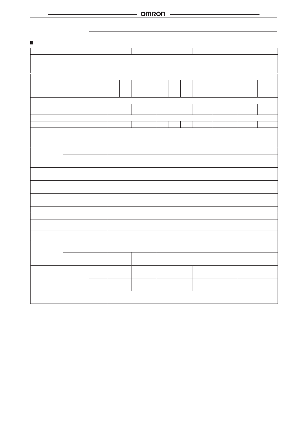
Specifications
Brass type
Type
Operating voltage 10 to 35 VDC
Rated supply voltage 24 VDC
Current consumption max. 15 mA at 24 VDC
Sensing object Ferrous metals
Mounting ((s)hielded,
(n)on–shielded) (see note 1)
Operating distance in mm 1,5 2,0 1,5 2,0 2,0 4,0 4,0 5,0 8,0 8,0 10,0 15,0
Tolerance of operating distance
Standard target size in mm
(L x W x H in mm, FE 37)
Differential travel 1 % ... 15 % of operating distance
Max. response frequency in kHz 5,0 5,0 2,0 0,6 1,0 0,5 0,3 0,5 0,25 0,15
Control output Type E2EL–... E1 type: NPN–NO
Max–Load 200 mA
Max–on–state
Voltage drop
Circuit protection Reverse polarity, output short–circuit
Indicator Operating indicator (yellow LED)
Ambient temperature
Humidity 35 to 95 % RH
Influence of temperature
Dielectric strength 1.500 VAC, 50/60 Hz for 1 min. between current carry parts and case
Electromagnetic compatibility EMC EN 60947–5–2
Vibration resistance Destruction: 10 to 70 Hz, 1,5 mm double amplitude for 1 hour each in X, Y and Z directions
Shock
resistance
Enclosure
rating
Connection
(see note 2)
Pre–wired 2 m PVC–cable, 3 x
Connector M8 plug M8 plug
∅6,5
s n s n s s n s s n s n
±10%
6,5x6,5x1 8x8x1 12x12x1 18x18x1 24x24x1 30x30x1 45x45x1
2,5 VDC (at 200mA load current and with 2 m cable)
Operating: –25° to 70°C
± 10 % max. of Sn at 23°C in temperature range of –25° to 70°C
Destruction: 300 m/s@ (approx. 30 G) for 6 times each in X, Y and Z directions
IP 67 (EN 60947–1)
0,14 mm@
M8 M12 M18 M30
E2 type: NPN–NC
F1 type: PNP–NO
F2 type: PNP–NC
2 m PVC–cable, 3 x 0,25 mm
M12 plug
M12 plug
2
2m PVC–cable, 3 x
2
0,5 mm
Weight in g Pre–wired long 45 50 75 115 260
short 43 48 70 100 200
Connector long 10 15 25 60 155
short 8 13 20 50 110
Material Case Brass
Sensing face PBTP
Note: 1. For detailed mounting instruction please refer to page 11.
2. PUR cable and different length on request.
3
E2EL
E2EL
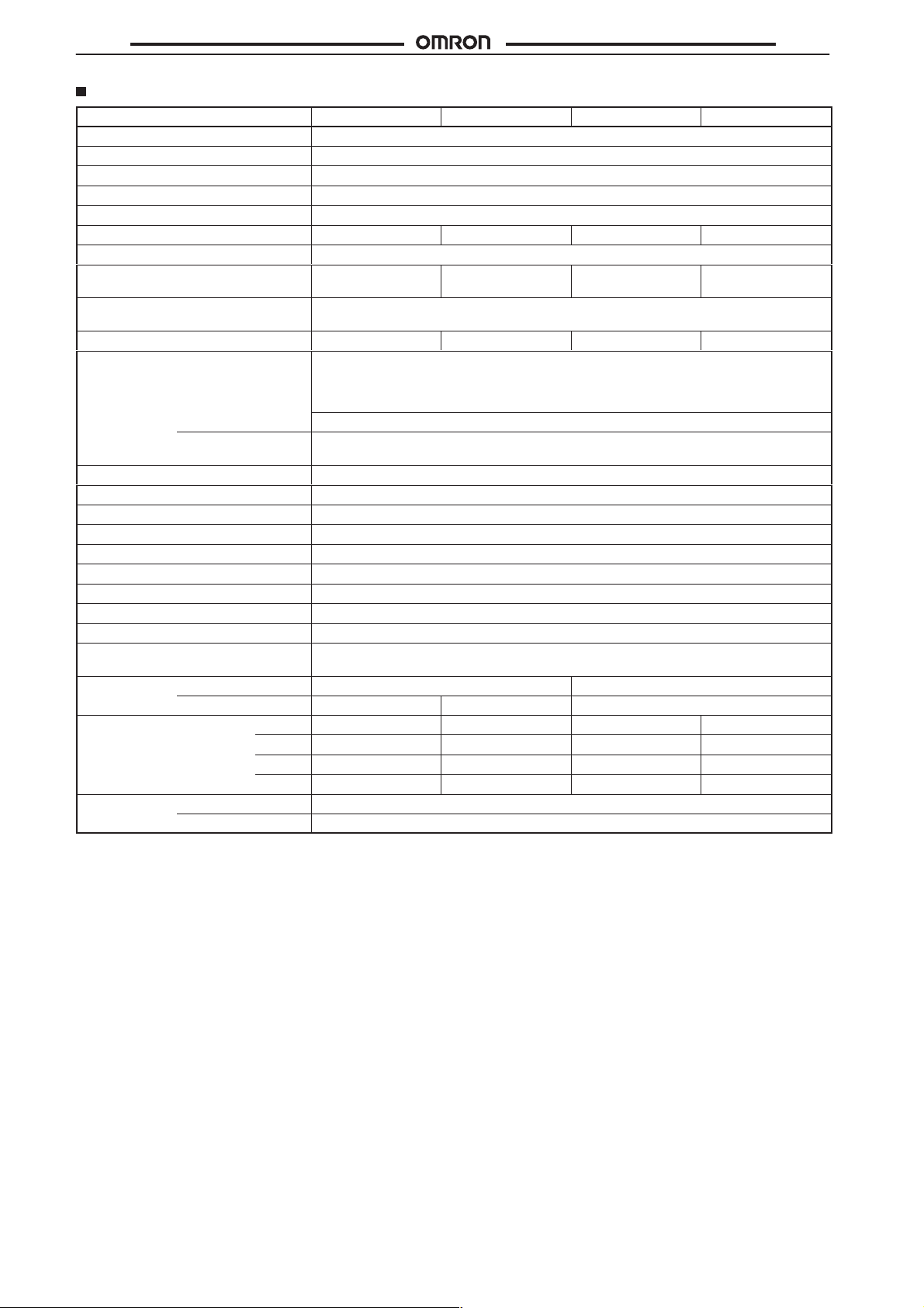
Stainless steel type
Type
Operating voltage 10 to 35 VDC
Rated supply voltage 24 VDC
Current consumption max. 15 mA at 24 VDC
Mounting (see note 1) Shielded
Sensing object Ferrous metals
Operating distance in mm 2,0 2,0 4,0 8,0
Tolerance of operating distance
Standard target size
(L x W x H in mm, FE 37)
Differential
travel
Max. response frequency in kHz 4,0 4,0 0,6 0,25
Control output Type E2EL–... E1 type: NPN–NO
Max–Load 200 mA
Max–on–state
Voltage drop
Circuit protection Reverse polarity, output short–circuit
Indicator Operating indicator (yellow LED)
Ambient temperature
Humidity 35 to 95 % RH
Influence of temperature
Dielectric strength 1.500 VAC, 50/60 Hz for 1 min. between current carry parts and case
Electromagnetic compatibility EMC EN 60947–5–2
Vibration resistance Destruction: 10 to 70 Hz, 1,5 mm double amplitude for 1 hour each in X, Y and Z directions
Shock resistance
Enclosure
rating
Connection
(see note 2)
Weight in g Pre–wired long 45 50 75 120
Material Case stainless steel 1.4305 / AISI 303
Pre–wired
Connector – M8 plug M12 plug
short 43 48 70 105
Connector long – 10 25 65
short – – 20 55
Sensing face PBTP
∅6,5
±10%
6,5x6,5x1 8x8x1 12x12x1 24x24x1
1 % ... 15 % of operating distance
E2 type: NPN–NC
F1 type: PNP–NO
F2 type: PNP–NC
2,5 VDC (at 200mA load current and with 2 m cable)
Operating: –25° to 70°C
± 10 % max. of Sn at 23°C in temperature range of –25° to 70°C
Destruction: 300 m/s@ (approx. 30 G) for 6 times each in X, Y and Z directions
IP 67 (EN 60947–1)
2 m PVC–cable, 3 x 0,14 mm@
M8 M12 M18
2 m PVC–cable, 3 x 0,25 mm
2
Note: 1. For detailed mounting instruction please refer to page 11.
2. PUR cable and different length on request.
4

E2EL
Engineering Data
Standardized characteristic for lateral approach
E2EL
standard target
approach
lateral approach
on
axial
axial distance related to effective operating distance
–1 –0,8 –0,6 –0,4 –0,2 0 0,2 0,4 0,6 0,8 1
lateral distance related to radius of ’active surface’ (r/r
Output Circuit Diagram and Timing Chart
E2EL–XjEj
NPN Output
Brown 1
1,2
1
0,8
0,6
0,4
0,2
0
E2EL-XjFj
PNP Output
off
’switch–on’ curve
’
switch–off’ curve
)
act
Brown 1
Main
circuit
E2EL–XjEj
NPN Output
Sensing object
Yellow indicator
Control output
4,7 kΩ
Yes
Not lit
ON
OFF
No
Lit
Load
Black 4 (or 2)
Blue 3
NO
NC
Main
circuit
E2EL–XjFj
PNP Output
Sensing object
Yellow indicator
Control output
4,7 kΩ
Yes
Not lit
ON
OFF
No
Lit
Black 4 (or 2)
Load
Blue 3
NO
0 V
NC
5

E2EL
Pin Arrangement at Connector Types
1. Connector M8 (viewed to plug pins)
Output
+ –
2. Connector M12 (viewed to plug pins)
E2EL
NO
3(–)
1 (+)2 free
4 Output
NC
3(–)
1 (+)2 Output
4 free
Dimensions
Note: 1. All units are in millimeters unless otherwise indicated.
2. Unless otherwise specified, a tolerance of ±0.4 mm applies to all dimensions. Values in parentheses () are cumulative values and
may exceed tolerance of ±0.4 mm.
3. The square j in the models represents the output configuration. Refer to Ordering Information.
Cable Types
E2EL–C1jR5 2M, E2EL–C2j–DS 2M E2EL–C2Mj 2M
E2EL–C1R5j–L 2M, E2EL–C2j–DSL 2M E2EL–C2Mj–L 2M
E2EL–X1R5j 2M, E2EL–X2j–DS 2M E2EL–X2Mj 2M
E2EL–X1R5j–L 2M, E2EL–X2j–DSL 2M E2EL–X2Mj–L 2M
6

E2EL
E2EL–X2j 2M, E2EL–X4j–D 2M, E2EL–X4j–DS 2M E2EL–X4Mj 2M
E2EL–X2j–L 2M, E2EL–X4j–DL 2M, E2EL–X4j–DSL 2M E2EL–X4Mj–L 2M
E2EL–X5j 2M, E2EL–X8j–D 2M, E2EL–X8j–DS 2M E2EL–X8Mj 2M
E2EL
E2EL–X5j–L 2M, E2EL–X8j–DL 2M, E2EL–X8j–DSL 2M E2EL–X8Mj–L 2M
E2EL–X10j 2M E2EL–X15Mj 2M
E2EL–X10j–L 2M E2EL–X15Mj–L 2M
7

E2EL
Plug Types
E2EL–C1R5j–M3 E2EL–C2Mj–M3
E2EL–C1R5j–M3L E2EL–C2Mj–M3L
E2EL–X1R5j–M3 E2EL–X2Mj–M3
E2EL
E2EL–X1R5j–M3L, E2EL–X2jDM3S E2EL–X2Mj–M3L
E2EL–X1R5j–M1 E2EL–X2Mj–M1
E2EL–X1R5j–M1L E2EL–X2Mj–M1L
E2EL–X2j–M1, E2EL–X4j–DM1, E2EL–X4j–DM1S E2EL–X4Mj–M1
8

E2EL
E2EL–X2j–M1L, E2EL–X4j–DM1L, E2EL–X4j–DM1SL E2EL–X4Mj–M1L
E2EL–X5j–M1, E2EL–X8j–DM1, E2EL–X8j–DM1S E2EL–X8Mj–M1
E2EL–X5j–M1L, E2EL–X8j–DM1L, E2EL–X8j–DM1SL E2EL–X8Mj–M1L
E2EL
E2EL–X10j–M1 E2EL–X15Mj–M1
E2EL–X10j–M1L E2EL–X15Mj–M1L
9

E2EL
Installation
Caution
Item Examples
Power Supply
Do not impose an excessive voltage on the E2EL, otherwise it
may explode or burn.
Do not impose 24 VAC on any E2EL model, otherwise it may
explode or burn.
Load short–circuit
Do not short–circuit the load, or the E2EL may explode or burn.
The E2EL’s short–circuit protection function is valid, if the polarity
of the supply voltage imposed is incorrect and within the rated
voltage range.
Wiring
Be sure to wire the E2EL and load correctly, otherwise it may
explode or burn.
E2EL
Correct Use
Installation
Power Reset Time
The Proximity Sensor is ready to operate within 100 ms after power
is supplied. If power supplies are connected to the Proximity Sensor
and load respectively , be sure to supply power to the Proximity Sensor before supplying power to the load.
Power OFF
The Proximity Sensor may output a pulse signal when it is turned off.
Therefore, it is recommended to turn off the load before turning off
the Proximity Sensor.
Power Supply Transformer
When using a DC power supply, make sure that the DC power supply has an insulated transformer . Do not use a DC power supply with
an auto–transformer.
Sensing Object
Metal Coating:
The sensing distance of the Proximity Sensor vary with the metal
coating on sensing objects.
Wiring
High–tension Lines
Wiring through Metal Conduit
If there a power or high–tension line near the cord of the Proximity
Sensor, wire the cord through an independent metal conduit to prevent against Proximity Sensor damage or malfunctioning.
Core Tractive Force
Do not pull cords with the tractive force exceeding the following:
pull force (N) = 20 x cable diameter ( mm)
Mounting
The Proximity Sensor must not be subjected to excessive shock
with a ha mmer when it is installed, otherwise the Proximity Sensor
may be damaged or lose the water–resistivity.
Environment
Water–Resistivity
Do not use the Proximity Sensor underwater, outdoors or in the rain.
Operating Environment
Be sure to use the Proximity Sensor within operating ambient temperature range and do not use the Proximity Sensor outdoors so
that its reliability and life expectancy can be maintained. Although
the Proximity Sensor is water resistive, a cover to protect the Proximity Sensor from water or soluble machining oil is reco mmended
so that its reliability and life expectancy can be maintained. Do not
use the Proximity Sensor in an environment with chemical gas (e.
G., strong alkaline or acid gases including nitric, chromic, and concentrated sulfuric acid gases).
10

E2EL
Item Examples Item
AND
(serial
connection)
OR
(parallel
connection)
The Sensors connected together must satisfy the
following conditions:
iL + (N–1) x i = Upper–limit of control output of each
Sensor
VS – N x VR = Load operating voltage
N = No. of Sensors
VR = Residual voltage of each Sensor
VS = Supply voltage
i = Current consumption of the Sensor
iL = Load current
If the MY Relay, which operate at 24 VDC, is used as a
load for example, a maximum of two Proximity Sensors
can be connected to the load.
The number of Sensors connected in parallel varies with
the Proximity Sensor model.
E2EL
Effects of Surrounding Metal
Shielded types:
Shielded types allow direct installation on metal plates in an embedded manner without performance change. A minimum distance
of 3sn is required between the active surface and a metallic surface
in front of the device. (Fig. 1).
For SUS shielded types the following minimum distances are required to avoid performance change (see Fig.2 and table below):
Shielded SUS Types
E2EL–C2j–DS
E2EL–X2j–DS
E2EL–X4j–DjS
E2EL–X8j–DjS
w3s
n
Fig.1: Shielded type (except SUS)
0,5 mm
0,5 mm
1,0 mm
2,0 mm
Free zone
Non–shielded types:
Installation of non–shielded types in metal require the minimum distances according to Fig. 3.
w2s
w3s
n
n
d
w3d
Fig.3: Non–shielded type
Freezone
w3s
n
Fig.2: Shielded SUS type
11

E2EL
E2EL
In the interest of product improvement, specifications are subject to change without notice.
ALL DIMENSIONS SHOWN ARE IN MILLIMETERS.
To convert millimeters into inches, multiply by 0.03937. To convert grams into ounces, multiply by 0.03527.
Sensor Business Unit
Carl–Benz–Straße 4
D–71154 NUFRINGEN (GERMANY)
Phone: +49–70 32–81 1–0
Fax: +49–70 32–811–199
12
Cat. No. D093-E2-1OMRON EUROPE B.V.
 Loading...