

Page 1

NEW
Proximity Sensor Ideal for
High Temperatures and
Cleaning Processes
E2E Quality Proximity Sensor
E2E Quality Proximity Sensor
Ideal for the Food and Beverage Industry
Ideal for the Food and Beverage Industry
-- SUS316L Body, IP69K Protection,
-- SUS316L Body, IP69K Protection,
Resistant to High Temperatures and Detergents --
Resistant to High Temperatures and Detergents --
E2E Quality Proximity Sensor
Ideal for the Food and Beverage Industry
-- SUS316L Body, IP69K Protection,
Resistant to High Temperatures and Detergents --
E2EH-X@@@
Improved
Improved
resistance to
resistance to
detergents and
detergents and
rusting
rusting
Improved
resistance to
detergents and
rusting
Water resistant under
high-temperature,
high-pressure
cleaning based on
DIN 40050-9.
(Pressure: 8,000 to
10,000 kPa, Water
temperature: 80˚C, For
30 s at all angles)
Applicable to
Applicable to
120
120
˚C
C
(with DC 3-
(with DC 3-
wire connection)
wire connection)
(Heat resistance
(Heat resistance
verified to 1,000
verified to 1,000
hours.)
hours.)
Applicable to
120˚C
(with DC 3wire connection)
(Heat resistance
verified to 1,000
hours.)
Resists typical
detergents and
disinfectants used in
the food industry.
Ordering Information
Sensing distance Output configuration Pre-wired modelsSize
M12
M18
M30
E2EH-X3D1
E2EH-X3D1-T
E2EH-X3B1
E2EH-X7D1
E2EH-X7D1-T
E2EH-X7B1
E2EH-X12D1
E2EH-X12D1-T
E2EH-X12B1
DC 2-wire, polarity
DC 2-wire, no polarity
DC 3-wire, PNP
DC 2-wire, polarity
DC 2-wire, no polarity
DC 3-wire, PNP
DC 2-wire, polarity
DC 2-wire, no polarity
DC 3-wire, PNP
M12 Connector models
3 mm
7 mm
12 mm
Shielded
Models with DC 3-wire, NPN outputs are also available. Use the following
model number: E2EH-X@C@.
Models with normally closed outputs are also available. Use the following
model number: E2EH-X@@2.
Sensor I/O Connectors suitable for high-temperature cleaning processes
are available: XS2F-E42@-@@@-E Series (105°C, protection equivalent
to IP67/IP69K).
E2EH-X3D1-M1G
---
E2EH-X3B1-M1
E2EH-X7D1-M1G
---
E2EH-X7B1-M1
E2EH-X12D1-M1G
---
E2EH-X12B1-M1
Page 2
Authorized Distributor:
Note: Specifications subject to change without notice.
Regional Headquarters
Cat. No. D106-E1-02
0407
OMRON Corporation
Industrial Automation Company
Sensing Devices Division H.Q.
Industrial Sensors Division
Shiokoji Horikawa, Shimogyo-ku,
Kyoto, 600-8530 Japan
Tel: (81)75-344-7022/Fax: (81)75-344-7107
OMRON EUROPE B.V.
Sensor Business Unit,
Carl-Benz-Str. 4, D-71154 Nufringen,
Germany
Tel: (49)7032-811-0/Fax: (49)7032-811-199
OMRON ELECTRONICS LLC
1 East Commerce Drive, Schaumburg,
IL 60173 U.S.A.
Tel: (1)847-843-7900/Fax: (1)847-843-8568
OMRON ASIA PACIFIC PTE. LTD.
83 Clemenceau Avenue,
#11-01, UE Square,
239920 Singapore
Tel: (65)6835-3011/Fax: (65)6835-2711
OMRON (CHINA) CO., LTD.
Room 2211, Bank of China Tower,
200 Yin Cheng Road (M),
Shanghai, 200120 China
Tel: (86)21-5037-2222/Fax: (86)21-5037-2200
• Before ordering, read page F-2 in the Sensor General Catalog concerning warranty, limitations of liability, and other related information.
• This document provides information mainly for selecting suitable models and does not contain precautions for correct use and other precautionary information. Always read the Instruction Sheet
included with the product before attempting to operate the product.
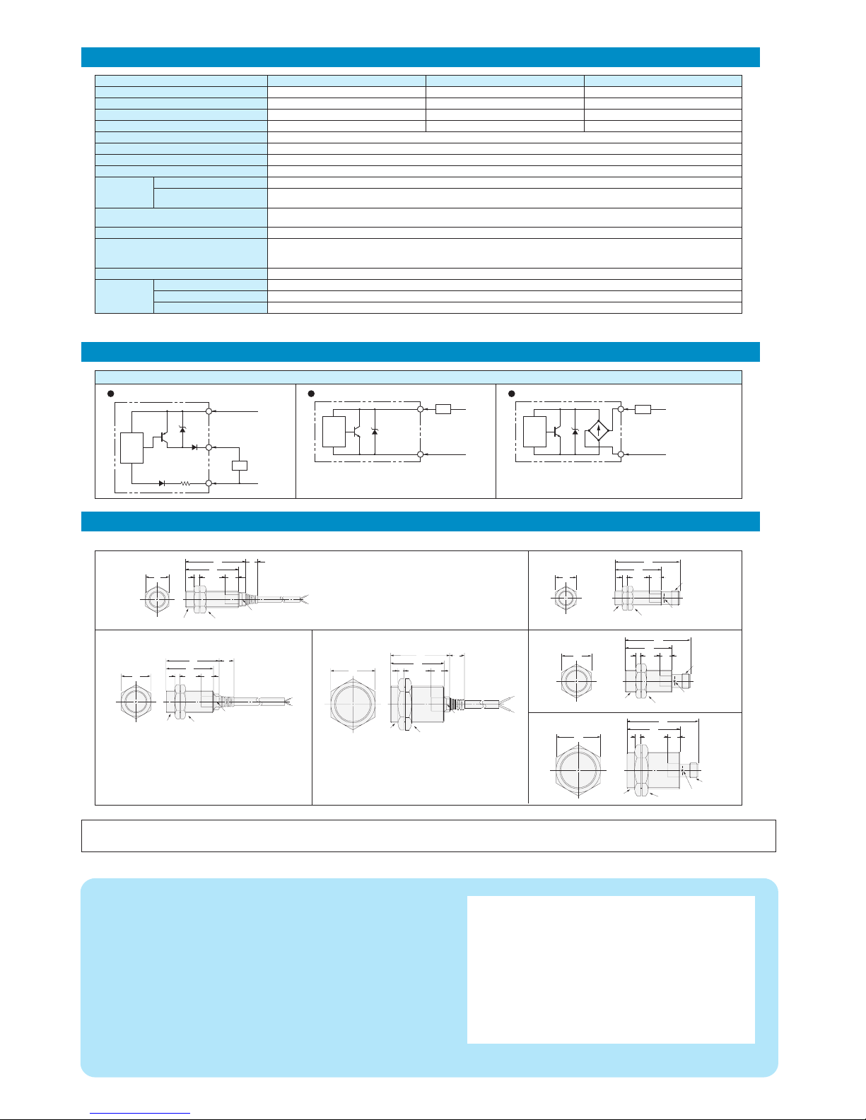
Dimensions
I/O Circuit Diagrams
Ratings and Specifications
Output circuit
E2EH-X@D@-T
The load can be connected to either the +V or 0 V side.
The E2EH-X@D@-T has no polarity. There is no need to be
concerned about the polarity.
Item
Load current
Residual voltage
Case, clamping nuts
Sensing surface
Cable
Size
Model
Sensing distance
Set distance
Differential travel
Power supply voltage (operating voltage range)
Current consumption
Leakage current
Control output
Indicators
Ambient temperature *2
Temperature influence
Degree of protection
Materials
M12 shielded M18 shielded M30 shielded
E2EH-X3@@
3 mm±10% 7mm±10% 12mm±10%
0 to 2.4 mm 0 to 5.6 mm 0 to 9.6 mm
15% max. of sensing distance
12 to 24 VDC, ripple (p-p): 10% max. (10 to 32 VDC) (24 VDC max. at 100°C or higher)
10 mA max. (DC 3-wire)
0.8 mA max. (DC 2-wire)
DC 2-wire models: 3 to 100 mA (3 to 50 mA at 100 to 110°C), DC 3-wire models: 100 mA max. (50 mA max. at 100°C or higher)
DC 2-wire models: 3 V max. (Load current: 100 mA, with 2-m cable; 5 V max. for models with model numbers ending in -T)
DC 3-wire models: 2 V max. (Load current: 100 mA, with 2-m cable)
DC 2-wire models: D1 models: Operating indicator (red) and setting indicator (yellow),
D2 models: Operating indicator (yellow); DC 3-wire models: Operating indicator (yellow)
DC 3-wire models: 0 to 100°C (0 to 120°C for 1,000 hours), DC 2-wire models: 0 to 100°C (0 to 110°C for 1,000 hours)
±10% max. of sensing distance at 23°C in the temperature range of 0 to 70°C
±15% max. of sensing distance at 23°C in the temperature range of 70 to 100°C
−15% to 20% of sensing distance at 23°C in the temperature range of 100 to 120°C
IEC IP67, DIN 40050-9 IP69K
Stainless steel (SUL316L)
PBT
Heat-resistant PVC
E2EH-X7@@ E2EH-X12@@
Refer to the Sensor General Catalog for the influence of surrounding metal and mutual interference and use the Sensor in a suitable environment.
Operation with power supplied for 1,000 h has been verified at 120°C for DC, 3-wire models and at 110°C for DC 2-wire models. Do not bend the cable repeatedly at 100°C or higher.
E2EH-X@D@
+V
(0 V)
0 V
(+V)
Load
Proximity
Sensor
main
circuit
Load
Brown 1
Blue 4 (NO), 2 (NC)
Proximity
Sensor
main
circuit
+V
0 V
Note 1.
Load
Brown 1
Black 4 (NO), 2 (NC)
Blue 3
Proximity
Sensor
main
circuit
+V
0 V
4-dia. heat-resistant PVC cable with two conductors
(Conductor cross section: 0.3 mm2, insulator diameter:
1.3 mm), Standard length: 2 m
4-dia. heat-resistant PVC cable with three conductors
(Conductor cross section: 0.3 mm2, insulator diameter:
1.3 mm), Standard length: 2 m
E2EH-X7@@
24
4
38
10
12
43
M18 × 1 Two clamping nuts
Indicator
(See note 1.)
4
17
38
10
53
E2EH-X3@@
4
17
38
10
9
43
(See note 1.)
M12 × 1 Two clamping nuts
Indicator
E2EH-X3@@-M1@
M12 × 1
M12 × 1
Two clamping nuts
Indicator
4
24
38
10
53
E2EH-X7@@-M1@
M18 × 1
Two clamping nuts
Indicator
M12 × 1
E2EH-X12@@-M1@
5
36
43
10
58
M30 × 1.5 Two clamping nuts
M12 × 1
Indicator
E2EH-X12@@
36
5
43
10
12
48
Indicator
(See note 1.)
M30 × 1.5
Two clamping nuts
Note 1.
2.
E2EH-X@B@
The load can be connected to either the +V
or 0 V side.
Note 1.
2.
Note: All units are in millimeters unless otherwise indicated.
Note 1.
6-dia. heat-resistant PVC cable with two conductors
(Conductor cross section: 0.5 mm2, insulator diameter:
1.9 mm), Standard length: 2 m
6-dia. heat-resistant PVC cable with three conductors
(Conductor cross section: 0.5 mm2, insulator diameter:
1.9 mm), Standard length: 2 m
Note 1.
6-dia. heat-resistant PVC cable with two conductors
(Conductor cross section: 0.5 mm2, insulator diameter:
1.9 mm), Standard length: 2 m
6-dia. heat-resistant PVC cable with three conductors
(Conductor cross section: 0.5 mm2, insulator diameter:
1.9 mm), Standard length: 2 m
Note 1.
 Loading...