

Page 1

Machine Automation Controller NJ-series
IO-Link Connection Guide
(EtherCAT(R) Host Communications)
OMRON Corporation
Proximity Sensor
(E2E-series IO-Link)
[IO-Link Master Unit]
OMRON Corporation
NX-series IO-Link Master Unit (NX-ILM[][][])
NX-series EtherCAT Coupler unit (NX-ECC20[])
P663-E1-01
Page 2

About Intellec t ua l Property Right s and Trademarks
Microsoft product screen shots reprinted with permission from Microsoft Corporation.
Windows is a registered trademark of Microsoft Corporation in the USA and other countries.
EtherCAT(R) is registered trademark and patented techn ology, licensed by Beckhof f Automation
GmbH, Germany.
Sysmac is a trademark or r egist ered trademark of OMRON Cor por at ion in Japan and other
countries for OMRON fact or y automation products.
Company names and product names in this document are the tr ademarks or registered
trademarks of their respe ctive companies.
Page 3

T a ble of Co ntent s
1. Related Manuals .......................................................................................... 1
2. T erms and Definitions ................................................................................. 2
3. Precautions .................................................................................................. 3
4. Overview ...................................................................................................... 4
5. Applicable Devices and Device Configuration ........................................ 5
5.1. Applicable Devices .................................................................................. 5
5.2. Device Configuration ............................................................................... 6
6. Communications Settings .......................................................................... 8
6.1. EtherCAT Connection Parameter ........................................................... 8
6.2. IO-Link Connection Parameter ............................................................... 8
6.3. Slave Terminal Configuration and Device Names .................................. 8
6.4. Device Variables ...................................................................................... 9
7. IO-Link Connectio n Procedure ................................................................. 11
7.1. Work Flow .............................................................................................. 11
7.2. Slave Terminal Setup ............................................................................ 13
7.3. Network Configuration for Host Communi catio ns ................................. 16
7.4. IO-Link Master Unit Setup ..................................................................... 20
7.5. Controller Setup .................................................................................... 23
7.6. IO-Link Communication Status Check .................................................. 30
8. Initialization method ................................................................................. 38
8.1. Initializing Controller .............................................................................. 38
8.2. Initializin g Salve Terminal ...................................................................... 38
9. Revision History ........................................................................................ 41
Page 4

1.Related Manuals
1
1. Related Manuals
To ensure system safety, make sure to always read and follow the information provided in all
Safety Precautions and Precaut ions for Safe Use in the manuals for each device which is
used in the system.
Cat. No. Model Manual name
W500 NJ501-[][][][]
NJ301-[][][][]
NJ101-[][][][]
W501 NJ501-[][][][]
NJ301-[][][][]
NJ101-[][][][]
W505 NJ501-[][][][]
NJ301-[][][][]
NJ101-[][][][]
W504 SYSMAC-SE2[][][] Sysmac Studio Version 1
W519 NX-ECC20[] NX-series EtherCAT(R) Coupler Unit
W567 NX-ILM[][][] NX-series IO-Link Master Unit
W570 NX-ILM[][][]
GX-ILM[][][]
9540393-4 E2E(Q)-[]-IL[] PROXIMITY SENSOR
9540292-0 E2E(Q)-[]-IL[] PROXIMITY SENSOR
NJ-series
CPU Unit
Hardware User's Manua l
NJ/NX-series
CPU Unit
Software User's Manual
NJ/NX-series
CPU Unit Built-in EtherCAT(R) Port
User's Manual
Operation Manual
User’s Manual
User’s Manual
IO-Link System
User’s Manual
INSTRUCTION SHEET
INDEX LIST
Page 5

2.Terms and Definitions
2
IO-Link device
IO-Link master
IO-Link Mode
Cyclic
I/O data
Process data
IODD file
2. Terms and Definitions
Term Explanation and Definition
A dev ice w ith a sensor or an actuator that can perform IO-Link
communications with an IO-Link master.
A dev ice t hat performs IO-Link communications with IO-Link devices in
an IO-Link System and th at simultaneously functions as a slave f or
host communications.
“IO-Link Master Unit” is used to ref er to a spec ific Un it in this docu ment.
A co m mu nication mode of an IO-Link master t o perform IO-Link
communications with IO-Link devices.
communications
Slave unit A generic name for a device that performs EtherCAT communications
Node address A node address is an address to identify a unit con nected to EtherCAT.
ESI file An ESI file contains infor mation unique to EtherCAT slave units in XML
Communications that ex change data in a fixed period with no ne ed f or
programming.
All target data in cyclic com m uni c at i ons with a host.
IO-Link Systems contain the foll ow ing two types of I/O data.
・Target data in cyclic communi cations w ith a host in an IO -Link master
・Target data in IO-Link devices for cyclic communications with an
IO-Link master
I/O data in IO-Link devices. You can allocate a maximum of 32 bytes of
process data in a master.
A de fin iti on file for an IO-Link device.
The parameter settings for an IO-Link device ca n be made by installing
this file in CX-ConfiguratorFDT.
with an EtherCAT master in an EtherCAT system. There are various
types of slaves such as ser vo drives that handle position data and I/O
terminals that handle bit signals.
format. Installing an ESI fi le enables Sysmac Studio to allocat e
EtherCAT slave process data and make other settings.
Page 6
3.Precautions
3
Indicates a potentially hazardous situation which, if not av oided,
damage.
Additional Information
This information is provid ed to increase understanding or make operation easier.
Symbol
3. Precautions
(1) Understand the speci fications of devices which are used in the system. A ll ow s ome
margin for ratings and performance. Provide safety measures, such as installing a safety
circuit, in order to ensure safety and minimize the risk of abnormal occurrence.
(2) To ensure system safety, make sure to always read and follow the in format ion provided in
all Safety Precautions and Pr ecautions for Safe Use in the manuals for each device
which is used in the system.
(3) The user is encouraged t o conf irm the standards and regulat ions that the system must
conform to.
(4) It is prohibited to copy, to reproduce, and to distribute a part or t he whole of this
document without the perm ission of OMRON Corporation.
(5) The information contai ned in this document is current as of July 2016. It is subject to
change for improvement without notice.
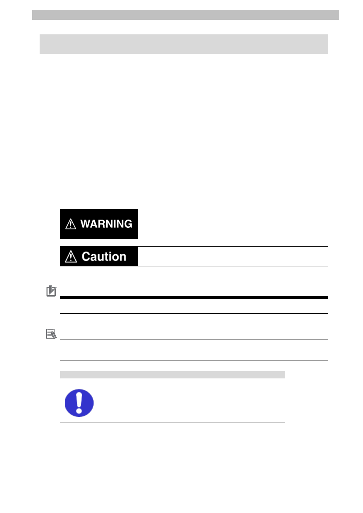
The following notations are used in this document.
may result in minor or moderate injury, or may result in serious
injury or death. Additionally there may be significant property
Indicates a potentially hazardous situation which, if not av oided,
may result in minor or moderate injury or property dam age.
Precautions for Correct Use
Precautions on what to do and w hat not to do to ensure proper operati on and performance.
Additional information to read as required.
The filled circle symbol indicates operations that you must do.
The specific operation is shown in the circle and ex plained in the text.
This example shows a general precau tion f or so meth ing th at you must do.
Page 7
4.Overview
4
ECC20[])
Slave Terminal
EtherCAT communications with
Controller
IO
Proximity Sensor
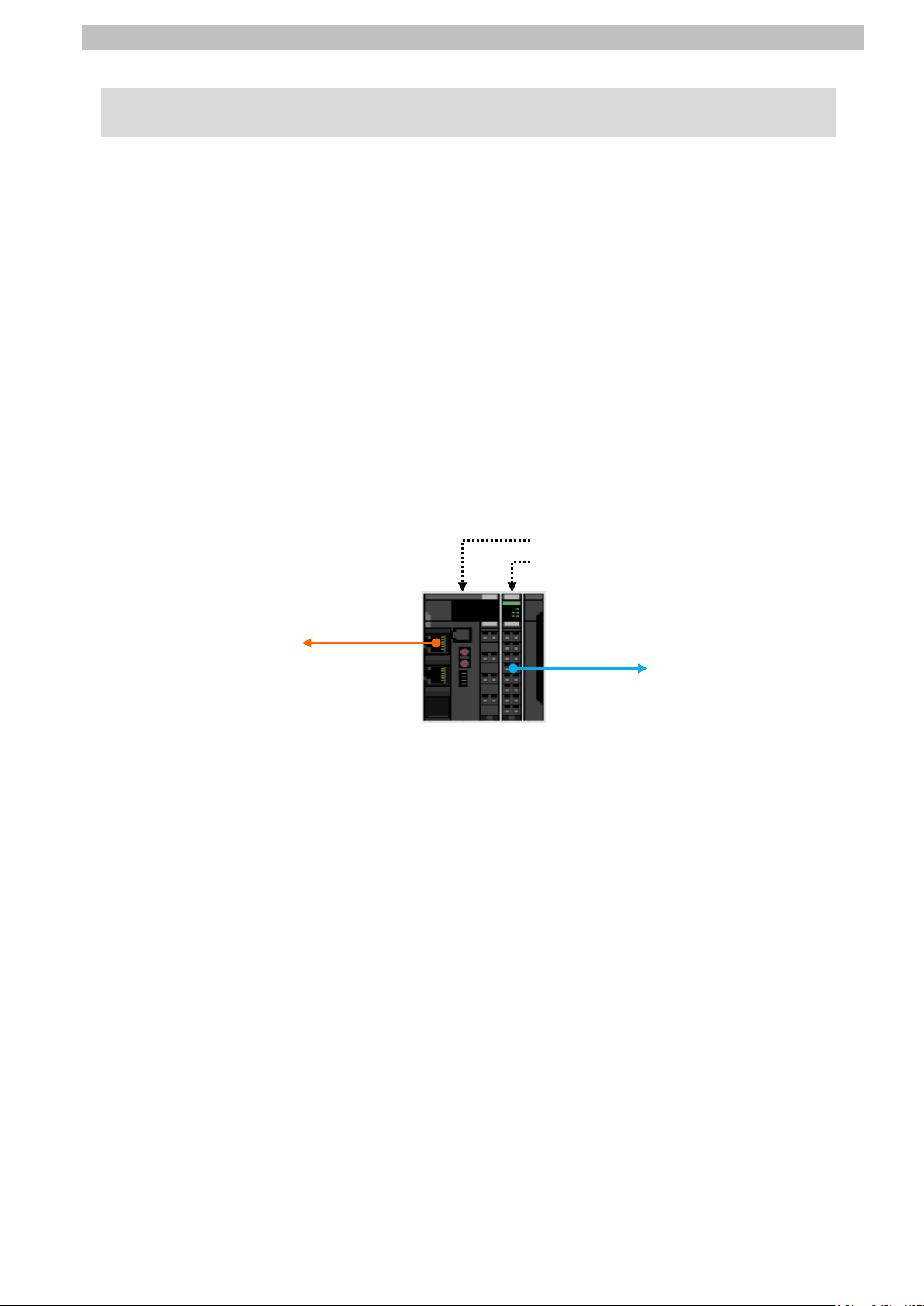
4. Overview
This document describes the procedures for connecting E2E-series IO-Link Proximity Sensor
(hereinafter referred to as Proximity Sensor) that is connec t ed via IO-Link to IO-Link Master
Unit (NX-ILM[][][]) to NJ-series Machine Automation Controller (hereinafter r ef er r ed t o as
Controller) via EtherC AT through EtherCAT Coupler Unit (NX-ECC20[]) to which IO-Link
Master Unit is connected and also for checking their connection status - all of which are
produced by OMRON Corpor at ion.
Refer to Section 6. Communicat ions Sett ings and Section 7. IO-Link Connection Procedure to
understand setting metho ds and key points to perform cyclic communications in the IO-Link
system.
In this document, a generic Et herCAT slave for EtherCAT communications is call ed " slave
unit", and a specific Ether CAT slave configured of E t her C AT Coupler Unit and IO-Link Master
Unit is called "Slave Terminal".
<Slave Terminal Configuration>
EtherCAT Coupler Unit (NXIO-Link Master Unit (NX-ILM[][][])
-Link communications with
Page 8

5.Applicable Devices and Device Configuration
5
Precautions for Correct Use
Additional Information
5. Applicable Devices and Device Configuration
5.1. Applicable Devices
The applicable devices are as follows:
Manufacturer Name Model
OMRON NJ-series CPU Un it NJ501-[][][][]
NJ301-[][][][]
NJ101-[][][][]
OMRON NX-series
EtherCAT Coupler Unit
OMRON NX-series
IO-Link Master Unit
OMRON E2E-series
IO-Link Proximity Sensor
NX-ECC20[]
NX-ILM[][][]
E2E(Q)-[]-IL[]
In this document, the d evices with models and vers ions liste d in 5.2. Dev ice Configuratio n are
used as examples of applicabl e devices to describe the procedur es for connecting the
devices and checking their connections.
You cannot use devices with versions lower than the versions listed in 5.2.
To use the above devices with models not listed in 5.2. or versions higher than those listed in
5.2., check the differ ences in the specifications by referr ing to the manuals before operating
the devices.
This document describes the procedures for establishing the network connections.
It does not provide inform at ion on operation, installation, wirin g method, device functionality,
or device operation, which is not r elat ed to the connection procedures.
Refer to the manuals or contact the device manufacturer.
Page 9
5.Applicable Devices and Device Configuration
6
Manufacturer
Name
Model
Version
OMRON
NJ-series CPU Un it
(Built-in EtherCAT port)
NJ501-1500
Ver.1.12
OMRON
Power Supply Unit
NJ-PA3001
OMRON
Sysmac Studio
SYSMAC-SE2[][][]
Ver.1.16
OMRON
CX-ConfiguratorFDT
(Included in Sysmac Studi o)
Ver.2.2
-
Personal computer
(OS: Windows 7)
- -
USB cable
(USB 2.0 type B connector )
- OMRON
Ethernet cable
(with industrial Ethernet connector)
XS5W-T421-[]M[]-K
OMRON
NX-series
EtherCAT Coupler Unit
NX-ECC202
Ver.1.2
OMRON
NX-series
IO-Link Master Unit
NX-ILM400
Ver.1.0
-
Unit power supply (24 VDC)
- -
I/O power supply (24 VDC )
-
OMRON
IO-Link Proximity Sensor
E2E-X3B4-IL3 2M
Ver.1.00
Precautions for Correct Use
Connect the cable shield to the connector hood at both ends of t he cable.
Precautions for Correct Use
Help.
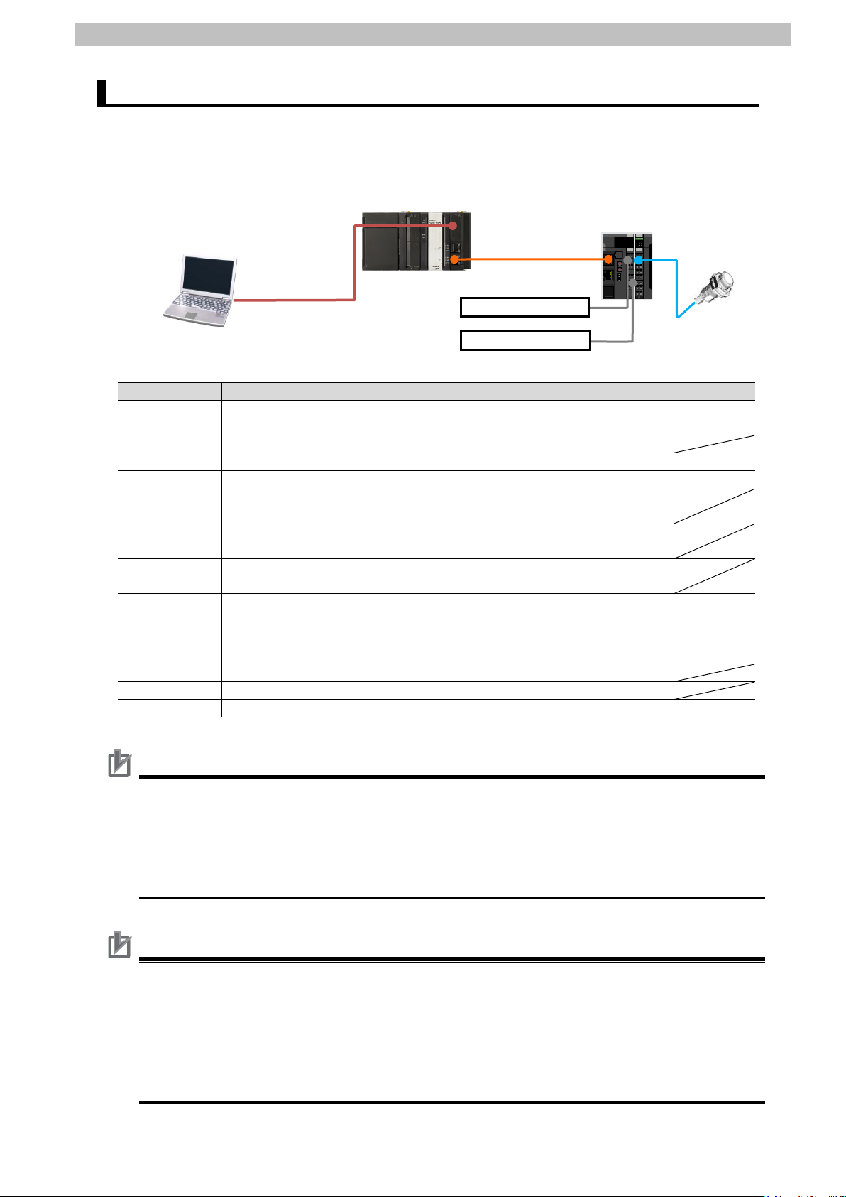
NJ501-1500
NX-ECC202+
NX-ILM400
Personal computer
Unit power supply
I/O power supply
E2E-X3B4-IL3 2M
5.2. Device Configuration
The hardware components to reproduce the connection procedures in this document are as
follows:
(Sysmac Studio and
CX-ConfiguratorFDT installed,
OS: Windows 7)
USB cable
(Built-in EtherCAT port)
Ethernet cable
The connection line of Ether CAT communications ca nnot be s hared with other Ethernet
networks. Do not use devices for Ethernet such as a switching hub.
Use an Ethernet cable (doubl e shielding with aluminum tape and br aiding) of Category 5 or
higher, and use a shielded connector of Cat egory 5 or higher.
Update Sysmac Studio an d CX -ConfiguratorFDT to the version specified in this Clause 5.2.
or to a higher version. If you use a version higher than the one spec ifie d, the procedures and
related screenshots described in Section 7. and subsequent sections may not be applicable.
In that case, use the equivalent pr oc edures described in this document by referring to the
Sysmac Studio Version 1 Operation Manual (Cat. No. W504) and ConfiguratorFDT Online
Page 10

5.Applicable Devices and Device Configuration
7
Additional Information
Additional Information
For specifications of Ether net cables and network wiring, refer t o Sect ion 4. EtherCAT
Network Wir in g of the NJ/NX-series CPU Unit Built-in EtherCAT(R) Port User's Manual (Cat.
No. W505).
Additional Information
For specifications of Unit and I/O power supplies for Slave Terminal, refer to the NX-series
EtherCAT(R) Coupler Unit User's Manual (Cat. No. W519).
The system configuration in this document uses USB for the connection between Personal
computer and Controller. For information on how to install the USB driv er, refer to A-1 Driver
Installation for Direct USB Cable Connection in Appendices of the Sysmac Studio Versio n 1
Operation Manual (Cat. No. W504).
Page 11

6.Communications Settings
8
Item
Set value
Remarks
Set the address using the hardw ar e sw it ches on Slave
Terminal.
Item name
Value
Port1 IO-Link Device Configuration Data / Master Control
IO-Link Mode (Default)
NX Unit number
Name
Model
Device name
0
EtherCAT Coupler Unit
NX-ECC202
E001
1
IO-Link Master Unit
NX-ILM400
N1
0
1
6. Communications Settings
This section describes the contents of parameter and device v ar iable settings that are all
defined in this document.
6.1. EtherCAT Connection Parameter
The parameter required fo r connecting Controller and Slave Terminal via EtherCAT is shown
below.
<Slave Terminal Setting>
Node address 1
6.2. IO-Link Connection Parameter
The parameter required fo r connecting IO-Link Master Unit and Proximity Sensor via IO-Link
is shown below.
In this document, Proxim ity Sensor is connected to Port 1 on IO-Link Master Unit.
<IO-Link Master Unit Setting>
6.3. Slave Terminal Configuration and Device Names
The Slave Terminal configuration a nd device names are shown below.
The default values are used for the device names. For slave units , t he default device names
are "E" followed by a serial number that starts from 001.
For NX Units, the default device names are N followed by a ser ial n umber that starts from 1.
<Slave Terminal configuration and device names>
Page 12

6.Communications Settings
9
Status whether the NX Unit is registered to Unit
configuration information or not.
Status whether the NX Unit I/O data is
controlled or not.
6.4. Device Variables
The I/O data (process dat a) for Proximity Sensor are allocated to the Cont r ol l er 's device
variables as PDO communicat ions data. The device variables are named automatically from a
combination of the device names and the port names.
The device variables and the data types are shown below.
Additional Information
With Sysmac Studio, two methods can be used to specify an arr ay for a data type.
After specifying, (1) is converted to (2), and the data type is always displayed as (2).
(1)BOOL[16] / (2) ARRAY[0..15] OF BOOL
In this document, the data type is simplified by displaying BOO L[ 16].
(The example above mea ns a BOOL data type w it h sixt een array elements.)
■Output area (Controller to Slave Terminal)
Device name Variable Data Type Description
N1_Port1_Output_Data01 BYTE[2] Port1 Output Data01
N1 N1_Port2_Output_Data01 BYTE[2] Port2 Output Data01
N1_Port3_Output_Data01 BYTE[2] Port3 Output Data01
N1_Port4_Output_Data01 BYTE[2] Port4 Output Data01
■Input area (Slave Terminal to Controller)
Device name Variable Data Type Description
E001_Sysmac_Error_Status BYTE Sysmac error status on Slave T erminal
E001_Observation BOOL Observation
E001_Minor_Fault BOOL Minor Fault
E001 E001_Partial_Fault BOOL Partial Fault
E001_Major_Fault BOOL Major Fault
E001_NX_Unit_Registration_Status_125 BOOL[126]
E001_NX_Unit_I_O_Data_Active_Status_125 BOOL[126]
N1_I_O_Port_Status WORD I/O Port Status
N1_Port1_IN_Data_Enable BOOL Port1 IN Data Enable
N1_Port2_IN_Data_Enable BOOL Port2 IN Data Enable
N1_Port3_IN_Data_Enable BOOL Port3 IN Data Enable
N1_Port4_IN_Data_Enable BOOL Port4 IN Data Enable
N1_Communication_Module_Error BOOL Communication Module Error
N1_IO_Pwr_On BOOL IO Power On
N1_Port1_2_I_O_Port_Error_Status WORD Port1_2 I/O Port Error Status
N1_Port1_Communication_Error BOOL Port1 Communication Error
N1_Port1_Short_Error BOOL Port1 Short Error
N1_Port1_Compare_Error BOOL Port1 Compare Error
N1 N1_Port1_Device_IO_Size_Error BOOL Port1 Device IO Size Error
N1_Port1_Device_Error BOOL Port1 Device Error
N1_Port1_Device_Information BOOL Port1 Device Warning
N1_Port1_PDO_Error BOOL Port1 PDO Error
N1_Port2_Communication_Error BOOL Port2 Communication Error
: (Same status as for Port 1) : :
N1_Port3_4_I_O_Port_Error_Status WORD Port3_4 I/O Port Error Status
Page 13
10
N1_Port3_Communication_Error BOOL Port3 Communication Error
Port1 Input Data01
<Stores the I/O data for Proximity Sensor.>
: (Same status as for Port 1) : :
N1_Port4_Communication_Error BOOL Port4 Communication Error
: (Same status as for Port 1) : :
N1_Port1_Input_Data01 BYTE[2]
[0] BYTE
N1 [1] BYTE
N1_Port2_Input_Data01 BYTE[2] Port2 Input Data01
N1_Port3_Input_Data01 BYTE[2] Port3 Input Data01
N1_Port4_Input_Data01 BYTE[2] Port4 Input Data01
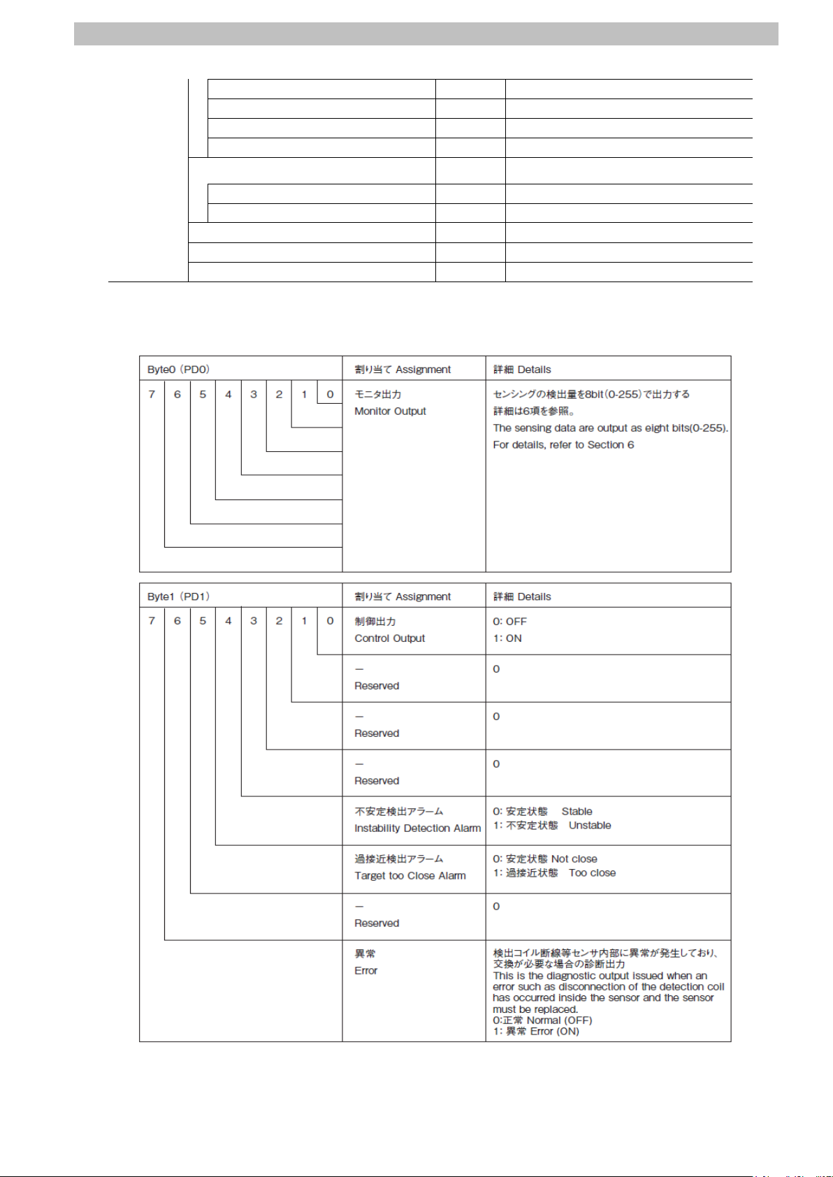
■I/O data (process data) f or Pr oximity Sensor
(Data to be stored in the device variable N1_Port1_Input_Data01 listed in the table above)
6.Communications Settings
<Stores Byte0 (PD0).>
<Stores Byte1 (PD1).>
Page 14

7.IO-Link Connection Procedure
11
7.2. Slave Terminal Setup
Communications
7.4. IO-Link Master Unit Setup
7.5. Controller Setup
7. IO-Link Connection Procedure
This section describes the pr ocedures for connecting Prox i mity Sensor to IO-Link Master Unit
via IO-Link and for connecting Controller to Slave Terminal configured of IO-Lin k Master U nit
on the EtherCAT network. The explanations of procedures for setting up Controller and Slave
Terminal given in this document are based o n the factory default settings.
For the initialization, refer t o Sect i on 8. Initialization Method.
7.1. Work Flow
Take the following steps to connect Proximity Sensor to I O-Link Master Unit via IO-Link and to
connect Controller to Slave Terminal configured of IO-Link Master Unit on t he EtherCAT
network.
Set up Slav e Terminal.
↓
7.2.1. Hardware Sett ings Configure Slave Terminal, set hardwar e sw it ches,
↓
7.3. Network Configuration for Host
↓
7.3.1. Start ing Sy smac Studio Start Sysmac Studio and connect onlin e w it h
↓
7.3.2. Setting up the EtherCAT
Network Configuration
↓
↓
7.4.1. Parameter Set tings Set the para m et er s for IO-Link Master Unit.
↓
and connect Proximity Sensor.
Set up the netw ork configuration for host
communications.
Controller.
Set up the EtherCAT network configurat ion.
Set up IO-Link Master Unit.
7.4.2. I/O Allocation Settings Set the I/O allocations for IO-Link Master Unit.
7.5.1. Setting t he Device Variables Set the device variables to use f or Sl ave Terminal.
7.5.2. Transferring the Project Data Connect online with Sysmac Studio and t r ansfer
↓
↓
↓
↓
Set up Controller.
the project data to Controller.
Page 15

7.IO-Link Connection Procedure
12
Check
7.6. IO-Link Communica t ion Status
↓
7.6.1. Checking the Connection Status Check the connection status of eac h device.
↓
7.6.2. Checking the Receiv e Data Check that the correct data are received.
Confirm that cyclic communicatio ns i n t he IO-Link
system performs norma lly.
Page 16

7.IO-Link Connection Procedure
13
applicable.
2
IO-Link Master Unit
End Cover
EtherCAT Coupler Unit
Rotary switches
7.2. Slave Terminal Setup
Set up Slave Terminal.
Hardware Settings 7.2.1.
Configure Slave Terminal, set hardware switches, and connect Proximity Sensor.
Precautions for Correct Use
Make sure that the power supp ly is OFF when you set up.
Make sure that EtherCAT
1
Coupler Unit and IO-Lin k Master
Unit are powered OFF.
*If either of them is ON, the
settings described in the
following steps and subsequen t
procedures may not be
Connect IO-Link Master Unit t o
EtherCAT Coupler Unit.
Check the position of the
3
hardware switches on Eth er C AT
Coupler Unit by referring to the
figure on the right.
Dip switch
Page 17

14
Set Rotary switches and DIP
6
(Cat. No. W519).
Unit power supply
I/O power supply
Unit power supply terminals
I/O power supply terminals
Ethernet cable
Communications
connector (IN)
4
switch as follows:
・Rotary switches
x10: 0
x1: 1
・DIP switch
4(ADR+100): OFF
*The node address is set to 1.
Connect an Ethernet cable t o
5
Communications connec tor (IN)
on EtherCAT Coupler Unit.
7.IO-Link Connection Procedure
Rotary switches DIP switch
Connect Unit power suppl y to
Unit power supply terminals on
EtherCAT Coupler Unit.
Connect I/O power supply t o I/O
power supply terminals.
*For details on power sup ply
specifications of NX-series
Slave Terminals, refer to
Section 5. Designing the Power
Supply System of the
NX-series EtherCAT(R)
Coupler Unit User’s Manual
Page 18

15
Connect Proximity Sens or t o
Black
Brown
Blue
Proximity Sensor
IO-Link
Master Unit
Port 1
7
Port 1 on IO-Link Master Unit.
7.IO-Link Connection Procedure
Page 19

7.IO-Link Connection Procedure
16
Additional Information
2
Terminal remains OFF.
3
Sysmac Studio.
4
End Cover
Power Supply Unit
Ethernet
cable
CPU Unit
Controller
Slave
Terminal
Personal
computer
Proximity Sensor
7.3. Network Configuration for Host Communications
Set up the network config ur at ion for host communications.
Starting Sysmac Studio 7.3.1.
Start Sysmac Studio and connect online with Controller.
Install Sysmac Studio and the USB driver on Personal computer beforehand.
For details on the online c onnection s to Contr oller, refer to Section 6. Online Connect ions to a
Controller of the Sysmac Studio Version 1 O peration Manual (Cat. No. W504).
Connect the Ethernet cabl e t o
1
the built-in EtherCAT port
(PORT2) on Controller, and
connect a USB cable to the
peripheral (USB) port. As shown
in 5.2. Device Configuration,
connect Personal computer and
Slave Terminal to Controller.
Turn ON Cont r ol ler and Unit
power supply for Slave Terminal.
*The I/O power supply for Sl ave
USB cable
Start Sysmac Studio.
*If the User Account Control
Dialog Box is displayed at start ,
make a selection to start
Sysmac Studio starts.
Click Connect to Device.
Page 20

17
The Connect to Device Dialog
Click Connect.
6
proceed with the processing.
8
5
Box is displayed.
Select Direct connection via
USB in the Connection type
Field.
Uncheck both Transfer from
Device and Display the
T r oubleshooting Dialog Box in
the Operation after Connection
Field.
A con firmation dialog box is
displayed. Check the contents
and click OK.
*The displayed dialog dep ends
on the status of Controller.
Check the contents and click
on an appropriate button t o
7.IO-Link Connection Procedure
The dialog box on the right is
7
displayed. Check the contents
and click OK.
The A ut o C onnect Project
Dialog Box is displayed online.
When an online connectio n is
established, a yellow bar is
displayed under the toolb ar.
The following panes are
displayed in this window.
Left: Multiview Explorer
Top right: Toolbox
Bottom right: Controller Status Pane
Middle top: Edit Pane
The following tabs are dis play ed
in the bottom middle of this
window.
Output Tab Page
Build Tab Page
Multiview
Explorer
Output Tab
Page
Edit Pane
Build Tab
Page
Toolbox
Controller
status
Pane
Page 21

7.IO-Link Connection Procedure
18
1
4
Setting up the EtherCAT Network Configuration 7.3.2.
Set up the EtherCAT network configuration.
Double-click EtherCAT under
Configurations and Setup in
the Multiview Explorer.
The EtherCAT Tab Page is
2
displayed in the Edit Pane.
Right-click Master on the
3
EtherCAT T ab Page in the Edit
Pane and select Compare and
Merge with Actual Network
Configuration.
A screen is displayed stating
"Get information is being
executed".
The Compare and Merge with
Actual Network Configur ation
Dialog Box is displayed.
Node address 1 and
NX-ECC202 Rev:1.2 ar e added
to the Actual network
configuration after the
comparison.
Click Apply actual network
configuration.
Page 22

19
A con firmation dialog box is
contents and click Close.
6
Close
7
8
5
displayed. Check the contents
and click Apply.
The confirmation dialog box on
the right is displayed. Chec k th e
As a node address 1 slave,
E001 NX-ECC202 Rev: 1. 2 is
added to the Network
configuration on Sysmac St udio.
Check that the data above is
added. Click
Node address 1 and E001
NX-ECC202 Rev:1.2 ar e added
to the EtherCAT Tab Page in the
Edit Pane.
.
7.IO-Link Connection Procedure
Select Offline from the
Controller Menu.
The yellow bar under the toolbar
disappears.
Page 23

7.IO-Link Connection Procedure
20
Additional Information
1
Configuration.
2
Settings
7.4. IO-Link Master Unit Setup
Set up IO-Link Master Unit.
Parameter Settings 7.4.1.
Set the parameters for IO -Link Master Unit.
In this document, the default values are used for the parameter sett ings of IO-Link Master Unit.
Check that IO-Link Mode is set as the communications mode for Port 1 to which proximity
Sensor is connected.
If you use the functions such as t he connected device verification and t he backup and
restoration of parameter settings in IO-Link devices, r efer t o the NX-series IO-Link Master
Unit User's Ma n ua l (Cat. No. W567) and the IO-Link System User's Manua l (Cat. No. W570).
Select NX-ECC202 Rev:1.2 on
the EtherCAT Tab Page in the
Edit Pane.
Check that the device name is
E001.
*The device name can be
changed as desired.
The device name you set is
used at the beginning of the
device variable name.
Click Edit Slave Terminal
The Node1:NX-ECC202 (E001)
Tab Page is displayed.
Select the NX Unit number 1
(IO-Link Master Unit).
The setting details are dis play ed
on the right side of the tab page.
Check that the device name is
N1.
*The device name can be
changed as desired. The
device name you set is used at
the beginning of the devic e
variable name.
Click Edit Unit Operation
.
Page 24

21
The Unit 1[Node1]:NX-ILM400
4
5
mode from the pull-down list.
3
(N1)Unit Operation Setti ngs Tab
Page is displayed.
Select ▼Port1 - Port1
IO-Link Device Configur at ion
Data from the pull-down list ( just
above the column "Item n am e")
to narrow down the parameter s.
A list of Port1 IO-Link Device
Configuration Data is displayed.
Check that IO-Link Mode is
selected as the set value of
Port1 IO-Link Device
Configuration Data/Master
Control.
*If IO-Link Mode is not displayed
in the Value Column, select the
7.IO-Link Connection Procedure
Page 25

7.IO-Link Connection Procedure
22
Additional Information
I/O Allocation Settings 7.4.2.
Set the I/O allocations for IO-Link Master Unit.
As the default values are used for the I/O allocations in this document, the I/O allocation
settings are made without editing any of the values.
To save the I/O data size for
unused ports, delete the I/O
entries for the unused por ts from
the I/O allocation settings.
The Edit I/O Allocat ion Set tings
Pane is displayed by clicking
Edit I/O Allocation Settings
shown on the right.
For information on how to edit,
refer to the IO-Link System
User’s Manual (Cat. No. W570).
Page 26

23
7.5. Controller Setup
1
2
Column and enter a name.
3
4
Set up Controller .
Setting the Device Variables 7.5.1.
Set the device variables to use f or Sl ave Terminal.
Double-click I/O Map under
Configurations and Setup in
the Multiview Explorer.
The I/O Map Tab Page is
displayed in the Edit Pane.
Check that Node1 is displ ayed
in the Position Column and that
the added Slave Terminal is
displayed in the Port Column.
*To manually set a variable
name for Slave Terminal, click
an entry cell in the Variable
7.IO-Link Connection Procedure
Right-click Node1 and select
Create Device Varia ble.
The variable names and t ypes
are set.
Page 27

24
Additional Information
The device variables are na med a utomatically from a combinati on of the device names and
the port names. For s lave units, the de fault dev ic e nam es ar e "E" fol lowed by a ser ial nu mber
that starts from 001. For N X Units, the default device names are " N" followed by a serial
number that starts from 1.
Additional Information
In this document, device var iab les are automatically named for a un it ( a slave).
Device variables can also be manually named for ports.
7.IO-Link Connection Procedure
Page 28

7.IO-Link Connection Procedure
25
2
3
Transferring the Project Data 7.5.2.
Connect online with Sysm ac St udio and transfer the project data to Controller.
When you transfer a user program, configuration data, s et up dat a, device
variables, or values in me mory used for CJ-series Units from Sysmac Studi o,
the devices or machines may perform unexpected operation r egardless of the
operating mode of CPU Unit.
Always confirm safety at the destination node before you transfer the project
data.
After you transfer the proj ec t dat a, CP U Unit restarts, and communicat io ns w ith
the slaves is cut off. During the period, the slave output s behave according to
the slave settings. The t ime that communications is cut off depends on the
EtherCAT network configuration.
Before you transfer the pr oject data, confirm that the slave settin gs w il l not
adversely affect t he device.
The Slave Unit will be reset after performing the synchroniz at ion i n st ep 7 and
subsequent steps, and th e device may perform unexpected operation.
Always confirm safety bef or e you perform the synchronization.
Select Check All Programs
1
from the Project Menu.
The Build Tab Page is displayed.
Check that "0 Errors" and "0
Warnings" ar e di splayed.
Select Rebuild Controller from
the Project Menu.
Page 29

26
A con firmation dialog box is
5
6
7
synchronized.
4
displayed. Confirm that there is
no problem, and click Yes.
Check that "0 Errors" and "0
Warnings" ar e di splayed on the
Build Tab Page.
Select Online from the
Controller Menu.
When an online connectio n is
established, a yellow bar is
displayed under the toolb ar.
Select Synchronize from the
Controller Menu.
7.IO-Link Connection Procedure
The Synchronization Dialog Box
8
is displayed.
Check that the data to transfer
(NJ501 in the right dialog box) is
selected.
Uncheck Do not transfer the
following. (All item s ar e not
transferred.) to make "Slave
Terminal Unit operation settings"
transfer.
Click T r ansfer To Controller.
*After executing T rans fer To
Controller, the Sysmac Studio
data is transferred to
Controller, and the data is
Page 30

27
A con firmation dialog box is
from step 1.
9
displayed. Confirm that there is
no problem, and click Yes.
A screen is displayed stating
"Synchronizing".
A con firmation dialog box is
displayed. Confirm that there is
no problem, and click No.
*Do not return to RUN mode.
7.IO-Link Connection Procedure
As shown in the figure on the
10
right, the font color that is used
to display the text of
synchronized data changes to
the same color as the one used
to specify "Synchronized".
Check that a message is
displayed stating "Cycle t he
power supply to the slave(s) t o
apply the settings". Click Close.
*When the Sysmac Studio
project data coincides wit h t he
Controller data, the
synchronized data will have the
same font color as the one
used to specify
"Synchronized".
*If the synchronization fai l s,
check the wiring and repeat
To reflect the settings, turn OFF
11
Unit power supply for Slave
Terminal, then turn it back ON.
Page 31

7.IO-Link Connection Procedure
28
15
16
Check that the LED status is as
12
shown below, which indicates
that Slave Terminal is able to
communicate.
RUN : Not lit
ERR : Not lit
TS : Green flashing
L/A IN : Green flickering
L/A OUT: Not lit
The LED status of Control ler is
13
as shown below when an error
occurs in EtherCAT
communications due to the
temporary interruption o f Un it
power supply for Slave Terminal.
NET RUN : Not lit
NET ERR : Red flashing
LINK/ACT : Yellow flashing
Select Troubleshooting from
14
the Tools Menu.
The Troubles hooting Dialog Box
is displayed. Check that a Lin k
OFF Error occurs as show n in
the figure on the right.
Click Reset A ll.
A con firmation dialog box is
displayed. Check the contents
and click Yes.
Page 32

29
Check that the error is not
18
17
displayed. Click × at the top
right of the Troubleshooting
Dialog Box to close.
Turn ON I/O power supply for
Slave Terminal.
7.IO-Link Connection Procedure
Page 33

7.IO-Link Connection Procedure
30
1
2
3
4
Stability indicator/
Communication indicator
7.6. IO-Link Communication Status Check
Confirm that cyclic communications in the IO-Link sy s t em performs normally.
Checking the Connection Status 7.6.1.
Check the connection stat us of e ach device.
Check with LED indicators on
Controller that PDO
communications via EtherCA T
performs normally.
The LED indicators in nor ma l st at us
are as follows:
NET RUN: Green lit
NET ERR: Not lit
LINK/ACT: Y ellow flashing
Check the LED indicators on
EtherCAT Coupler Unit.
The LED indicators in nor ma l status
are as follows:
RUN: Green lit
TS: Green lit
ERR: Not lit
L/A I N: G r een f li ckering
L/A OUT: Not lit
Check the LED indicators on
IO-Link Master Unit.
The LED indicators in nor ma l status
are as follows:
TS: Green lit
1-C: Green lit
1-E: Not lit
Check the LED indicator on
Proximity Sensor.
The LED indicators in nor ma l status
are as follows:
Communication indicator :
Stability indicator /
Green blinking
Page 34

7.IO-Link Connection Procedure
31
1
・・・
Checking the Receive Data 7.6.2.
Check that the correct data ar e r eceived.
Install CX-ConfiguratorFDT on Personal computer beforehand.
If you wire the I/O in the state where the dev ices are pow ered O N, doin g so ma y
cause damage to the devices .
Always read and follow th e in formation provided in all safety pr ecaut ions in the
manuals for each device to be wired.
If you change the variable values on a Watch Tab Page when Sysmac Studio is
online with CPU Unit, the devices connected to the output un it may operate
regardless of the operating mode of CPU Unit.
Always ensure safety before you change the variable v alues on a Watch T ab
Page when Sysmac Studi o is online with CPU Unit
Select Watch Tab Page from the
View Menu.
Select the Watch1 Tab.
2
Click Input Name and enter the
3
following variable names f or
monitoring. Select the display
format of each variable as shown
below.
Name: N1_Port1_Input_Data01[0]
Display format: Decimal
Name: N1_Port1_Input_Data01[1]
Display format: Binary
Start CX-ConfiguratorFDT.
4
Page 35

32
CX-ConfiguratorFDT starts.
7
5
Right-click MyNetwork in the
Network View and select Add from
the menu.
The A dd Dialog Box is displayed.
6
Select Nx built-in EtherCAT.
Click Yes.
7.IO-Link Connection Procedure
Check that <OMRON EtherCAT>
Nx built-in Ether C AT is added under
MyNetwork in the Network View.
Page 36

33
Right-click <OMRON EtherCAT>
8
Nx built-in EtherCAT and select
Scan - Create Network from the
menu.
7.IO-Link Connection Procedure
The Lifelist Dialog Box is displayed
9
after completing the networ k s can.
Check that <OMRON EtherCAT:1>
NX-ECC Coupler is adde d under Nx
built-in EtherCAT.
Click Add All and Cont i nue.
Page 37

34
The Lifelist Dialog Box is displayed
11
10
again after completing the network
scan.
Check that <IO-Link
Port_1:NOT_APPLICABLE>
E2E-X3B4-IL3 IODD1.1 is added
under NX-ILM400.
Click Add All and Conti nue.
7.IO-Link Connection Procedure
Check that the network
configuration is created in the
Network View as shown on the right.
Right-click <IO-Link Port_1:->
12
E2E-X3B4-IL3 IODD1.1 and select
Go online from the menu.
Page 38

35
Check that Proximity Sensor is
16
13
connected online.
Right-click <IO-Link Port_1:->
E2E-X3B4-IL3 IODD1.1 and select
Configuration from the menu.
*When <IO-Link Port_1:->
E2E-X3B4-IL3 IODD1.1 is
displayed in bold italic font,
Proximity Sensor is connected
online.
7.IO-Link Connection Procedure
The <IO-Link Port_1:-> E2E-X3B4
14
-IL3 IODD1.1 - Configuration Tab
Page is displayed.
Select Observation listed under
15
Menu on the <IO-Link Por t_1:->
E2E-X3B4-IL3 IODD1.1 –
Configuration Tab Page.
If Process Data In on the right side
of the tab page is not expanded,
click the + Button of Process Data In
to expand.
Click the icon (Enable or disable
cyclic read from device for dynamic
variables) on the <IO-Link Port_1:->
E2E-X3B4-IL3 IODD1.1 Configuration Tab Page.
The present values of the process
data for Proximity Sensor ar e
displayed in the Value Column.
Page 39

36
Make sure that there is no sensi ng
18
Sensor.
described in step 18.
20
Operation indicator
(Orange) is not lit.
Sensing object
Operation indicator
(Orange) is lit.
17
object in front of Proximity Sensor
and that Operation indicator is not
lit.
Check that the values of P r oxi m it y
Sensor in CX-ConfiguratorFDT are
as shown below.
Detection Level: 63
Sensor Output: OFF
*The value of the detectio n level
differs depending o n the
environmental settings o f Proximity
7.IO-Link Connection Procedure
Check that the online values on t he
19
Watch Tab Page of Sysmac Studio
are as shown below.
N1_Port1_Input_Data01[0]
: 63
N1_Port1_Input_Data01[1]
: 0000 0000 (Bit 0 is 0.)
*For details on each of the
variables, refer to 6.4. Device
Variables.
*You can check that the monitor
output (Detection Level) o f Port 1 is
63 and that the control output
(Sensor Output) is OFF; t hese
values are the same as the ones
Place Sensing object in fr ont of
Proximity Sensor and che c k th at
Operation indicator is lit in or ange.
Page 40

37
Check that the values of P r oxi m it y
Sensor.
described in step 21.
21
Sensor in CX-ConfiguratorFDT are
as shown below.
Detection Level: 133
Sensor Output: ON
*The value of the detectio n level
differs depending o n the
environmental settings of Proximity
7.IO-Link Connection Procedure
Check that the online values on t he
22
Watch Tab Page of Sysmac Studio
are as shown below.
N1_Port1_Input_Data01[0]
: 133
N1_Port1_Input_Data01[1]
: 0000 0001 (Bit 0 is 1.)
*For details on each of the
variables, refer to 6.4. Device
Variables.
*You can check that the monitor
output (Detection Level) o f Port 1 is
133 and that the control out put
(Sensor Output) is ON; th ese
values are the same as the ones
Page 41

8.Initialization method
38
EtherCAT Coupler Unit
8. Init ia l iz a tion method
The setting procedures in t his document are based on the factory default settings.
Some settings may not be appl icable unless you use the devices with t he factory default
settings.
8.1. Initializing Controller
To initialize the Controller settings, it is nece ssar y to initialize CPU Unit.
Change the operating mode of Controller to PROGRAM mode and select Clear All Memory
from the Controller Menu in Sysmac Studio. The Clear All Memory Dialog Box is displayed.
Check the contents and click OK.
8.2. Initializing Salve Terminal
To initialize the Slave Terminal settings, connect S lave Terminal directly to Personal co m put er
on which Sysmac Studio r uns.
(1) Connect the USB cable to the peripheral USB port on EtherC AT Coupler unit.
USB cable
Page 42

8.Initialization method
39
(2) Select NX-ECC202 on the EtherCAT Tab Page in the Edit Pane.
Click Edit Slave Terminal Configuration for the value of Slave Terminal Configuration.
(3) The connected Slave Terminal configuration is displayed. Click Online.
(4) Right-click Unit 0 (EtherCA T Cou pler Unit) after checking the online connection.
Select Clear All Memory from the menu.
Page 43

8.Initialization method
40
Precautions for Correct Use
(5) The Clear All Memory for Coupler Dialog Box is displayed. Check that Coupler + NX Units
is selected . Click Execute.
In the initialization of Slave Terminal, the backup data for the IO -Link devices that is stored in
IO-Link Master Unit is not clear ed. If you need to clear the backup dat a st or ed in IO-Link
Master Unit, refer to Clearing Backup Data in 7-4-2 Backing U p Set t ings of the IO-Link
System User’s Manual (Cat. No. W570) to clear the backup data.
Page 44

41
9. Revision History
code
Revision
01 July 5, 2016 Firs t edition
Date of revision Description of revision
9.Revision History
Page 45

42
Page 46

2016
P663-E1-01
0716-(-)
 Loading...