

Omron E2E DATASHEET

Oil resistant Cylindrical Proximity Sensor (Automotive)
E2E
Designed and tested for
Automotive assembly lines
• tested oil resistance on commonly us ed lu bricants in
Automotive industry
Ordering Information
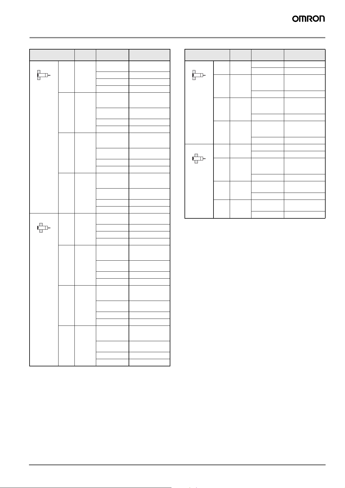
DC 2-wire/Pre-wired Models - enhanced oil resistant PUR/PE cable
Self-diagnostic
output function
No Shielded M8 2 mm E2E-X2D1-U E2E-X2D2-U
Size Sensing distance Model
NO NC
M12 3 mm E2E-X3D1-U E2E-X3D2-U
M18 7 mm E2E-X7D1-U E2E-X7D2-U
M30 10 mm E2E-X10D1-U E2E-X10D2-U
DC 2-wire/Pigtail-connector - enhanced oil resistant PUR/PE cable
Self-diagnostic
output function
No Shielded M8 2 mm E2E-X2D1-M1TGJ-U 0.3 M E2E-X2D2-M1TGJ-U 0.3 M
DC 2-wire/Pre-wired Models - PVC cable
Self-diagnostic
output function
Yes Shielded M12 3 mm E2E-X3D1S (See note 1.) ---
Unshielded M12 8 mm E2E-X8MD1S (See note 1.) ---
No Shielded M8 2 mm E2E-X2D1-N (See notes 2 and 3.) E2E-X2D2-N (See note 3.)
Unshielded M8 4 mm E2E-X4MD1 (See notes 2 and 3.) E2E-X4MD2
Size Sensing distance Model
NO NC
M12 3 mm E2E-X3D1-M1TGJ-U 0.3 M E2E-X3D2-M1TGJ-U 0.3 M
M18 7 mm E2E-X7D1-M1TGJ-U 0.3 M E2E-X7D2-M1TGJ-U 0.3 M
M30 10 mm E2E-X10D1-M1TGJ-U 0.3 M E2E-X10D2-M1TGJ-U 0.3 M
Size Sensing distance Model
NO NC
M18 7 mm E2E-X7D1S (See note 1.) --M30 10 mm E2E-X10D1S (See note 1.) ---
M18 14 mm E2E-X14MD1S (See note 1.) --M30 20 mm E2E-X20MD1S (See note 1.) ---
M12 3 mm E2E-X3D1-N (See notes 1, 2 and 3.) E2E-X3D2-N (See note 3.)
M18 7 mm E2E-X7D1-N (See notes 1, 2 and 3.) E2E-X7D2-N (See note 3.)
M30 10 mm E2E-X10D1-N (See notes 1, 2 and 3.) E2E-X10D2-N
M12 8 mm E2E-X8MD1 (See notes 1, 2 and 3.) E2E-X8MD2
M18 14 mm E2E-X14MD1 (See notes 1, 2 and 3.) E2E-X14MD2
M30 20 mm E2E-X20MD1 (See notes 1, 2 and 3. E2E-X20MD2
*1. In addition to the above models, E2E-X@@15 models (e.g., E2E-X3D15-N), which are different in frequency from the above models, are available.
*2. E2E models with a robotics cable are available as well. The model number of a model with a robotics cable has the suffix “-R”
(e.g., E2E-X3D1-R).
*3. Cables with a length of 5 m are also available. Specify the cable length at the end of the model number (e.g., E2E-X3D1-N 5M).
1E2E

DC 2-wire/Connector Models
Connector Self-diagnostic
M12 Yes Shielded M12 3 mm E2E-X3D1S-M1 ---
M8 Shielded M8 2 mm E2E-X2D1-M3G E2E-X2D2-M3G
output function
Unshielded M12 8 mm E2E-X8MD1S-M1 ---
No Shielded M8 2 mm E2E-X2D1-M1G E2E-X2D2-M1G
Unshielded M8 4 mm E2E-X4MD1-M1G E2E-X4MD2-M1G
Unshielded 4 mm E2E-X4MD1-M3G E2E-X4MD2-M3G
Size Sensing
M18 7 mm E2E-X7D1S-M1 --M30 10 mm E2E-X10D1S-M1 ---
M18 14 mm E2E-X14MD1S-M1 --M30 20 mm E2E-X20MD1S-M1 ---
M12 3 mm E2E-X3D1-M1G (See note.) E2E-X3D2-M1G
M18 7 mm E2E-X7D1-M1G (See note.) E2E-X7D2-M1G
M30 10 mm E2E-X10D1-M1G (See note.) E2E-X10D2-M1G
M12 8 mm E2E-X8MD1-M1G (See note.) E2E-X8MD2-M1G
M18 14 mm E2E-X14MD1-M1G (See note.) E2E-X14MD2-M1G
M30 20 mm E2E-X20MD1-M1G (See note.) E2E-X20MD2-M1G
distance
NO NC
Model
Note: In addition to the above models, E2E-X@D15-M1G models (e.g., E2E-X3D15-M1G), which are different in frequency from the above models, are available.
DC 2-wire/Pre-wired Connector Models
Size Sensing distance Operation mode Polarity Model
Shielded M12 3 mm NO Yes E2E-X3D1-M1GJ
No E2E-X3D1-M1J-T
M18 7 mm Yes E2E-X7D1-M1GJ
No E2E-X7D1-M1J-T
M30 10 mm Yes E2E-X10D1-M1GJ
No E2E-X10D1-M1J-T
Unshielded M12 8 mm Yes E2E-X8MD1-M1GJ
M18 14 mm E2E-X14MD1-M1GJ
M30 20 mm E2E-X20MD1-M1GJ
*1. A model with no polarity has a residual voltage of 5 V, which must be taken into consideration together with the interface condition (the PLC’s ON voltage, for
example) when connecting the Proximity Sensor to a load.
*2. The standard cable length is 300 mm. Models are also available with 500 mm and 1 m cables.
Connector Pin Assignments of DC 2-wire Model
The connector pin assignments of each new E2E DC 2-wire conforms to IEC947-5-2 Table III.
The following E2E models with conventional connector pin assignments are available as well.
Size Operation mode Model Size Operation mode Model
Shielded M8 NO E2E-X2D1-M1 Unshielded M8 NO E2E-X4MD1-M1
NC E2E-X2D2-M1 NC E2E-X4MD2-M1
M12 NO E2E-X3D1-M1 M12 NO E2E-X8MD1-M1
NC E2E-X3D2-M1 NC E2E-X8MD2-M1
M18 NO E2E-X7D1-M1 M18 NO E2E-X14MD1-M1
NC E2E-X7D2-M1 NC E2E-X14MD2-M1
M30 NO E2E-X10D1-M1 M30 NO E2E-X20MD1-M1
NC E2E-X10D2-M1 NC E2E-X20MD2-M1
2 Inductive Sensors
DC 3-wire/Pre-wired Models
Size Sensing
distance
Shielded M8 1.5 mm NPN NO
M12 2 mm NPN NO
M18 5 mm NPN NO
M30 10 mm NPN NO
Unshielded M8 2 mm NPN NO
M12 5 mm NPN NO
M18 10 mm NPN NO
M30 18 mm NPN NO
Output
configuration
NPN NC
PNP NO
PNP NC
NPN NC
PNP NO
PNP NC
NPN NC
PNP NO
PNP NC
NPN NC
PNP NO
PNP NC
NPN NC
PNP NO
PNP NC
NPN NC
PNP NO
PNP NC
NPN NC
PNP NO
PNP NC
NPN NC
PNP NO
PNP NC
Model
E2E-X1R5E1
(See notes 1 and 2.)
E2E-X1R5E2
E2E-X1R5F1
E2E-X1R5F2
E2E-X2E1
(See notes 1, 2, 3,
and 4.)
E2E-X2E2
(See notes 3 and 4.)
E2E-X2F1
E2E-X2F2
E2E-X5E1
(See notes 1, 2, 3,
and 4.)
E2E-X5E2
(See notes 3 and 4.)
E2E-X5F1
E2E-X5F2
E2E-X10E1
(See notes 1, 2, 3,
and 4.)
E2E-X10E2
(See notes 3 and 4.)
E2E-X10F1
E2E-X10F2
E2E-X2ME1
(See note 2.)
E2E-X2ME2
E2E-X2MF1
E2E-X2MF2
E2E-X5ME1
(See notes 1, 2, 3,
and 4.)
E2E-X5ME2
(See notes 3 and 4.)
E2E-X5MF1
E2E-X5MF2
E2E-X10ME1
(See notes 1, 2, 3,
and 4.)
E2E-X10ME2
(see notes 3 and 4.)
E2E-X10MF1
E2E-X10MF2
E2E-X18ME1
(See notes 1, 2, 3,
and 4.)
E2E-X18ME2
(See notes 3 and 4.)
E2E-X18MF1
E2E-X18MF2
AC 2-wire/Pre-wired Models
Size Sensing
distance
Shielded M8 1.5 mm NO E2E-X1R5Y1
M12 2 mm NO E2E-X2Y1
M18 5 mm NO E2E-X5Y1
M30 10 mm NO E2E-X10Y1
Unshielded M8 2 mm NO E2E-X2MY1
M12 5 mm NO E2E-X5MY1
M18 10 mm NO E2E-X10MY1
M30 18 mm NO E2E-X18MY1
Note: 1. Models with a different frequency are also available. These models are
E2E-X@Y@5 (e.g., E2E-X5Y15).
2. Cables with a length of 5 m are also available. Specify the cable length
at the end of the model number (e.g., E2E-X2Y1 5M).
Operation
mode
Model
NC E2E-X1R5Y2
(See notes 1 and
2.)
NC E2E-X2Y2
(See notes 1 and
2.)
NC E2E-X5Y2
(See notes 1 and
2.)
NC E2E-X10Y2
NC E2E-X2MY2
(See notes 1 and
2.)
NC E2E-X5MY2
(See note 1.)
NC E2E-X10MY2
(See note 1.)
NC E2E-X18MY2
Note: 1. Cables with a length of 5 m are also available. Specify the cable length
at the end of the model number (e.g., E2E-X2E1 5M).
2. Models with a robotics cable are also available. These models are
E2E-X@E1-R (e.g., E2E-X5E1-R).
3. Models with a different frequency are also available. These models are
E2E-X@E@5 (e.g., E2E-X5E15).
4. These models have e-CON connectors (0.3 m cable length), which is
indicated by the suffix “-ECON” (e.g., E2E-X2E1-ECON).
3E2E
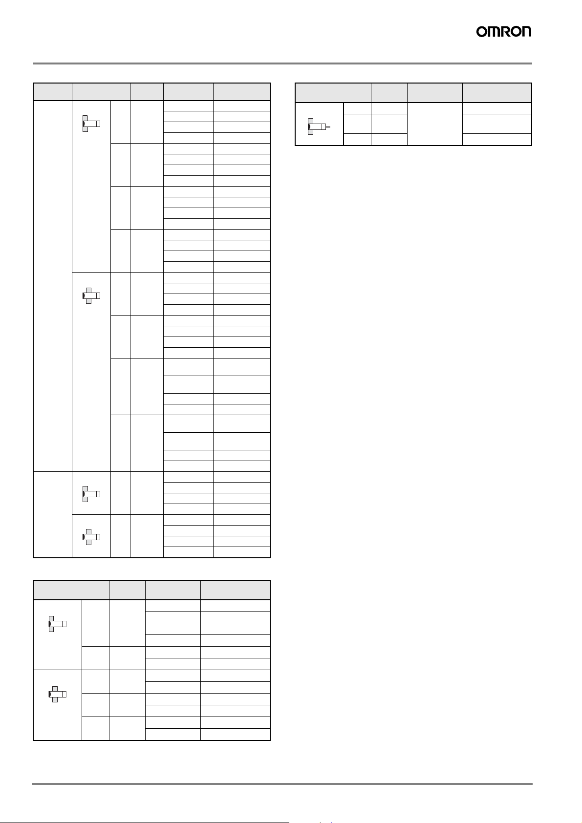
DC 3-wire/Connector Models
Connector Size Sensing
M12 Shielded M8 1.5 mm NPN NO E2E-X1R5E1-M1
Unshielded M8 2 mm NPN NO E2E-X2ME1-M1
M8 Shielded M8 1.5 mm NPN NO E2E-X1R5E1-M3
Unshielded M8 2 mm NPN NO E2E-X2ME1-M3
distance
M12 2 mm NPN NO E2E-X2E1-M1
M18 5 mm NPN NO E2E-X5E1-M1
M30 10 mm NPN NO E2E-X10E1-M1
M12 5 mm NPN NO E2E-X5ME1-M1
M18 10 mm NPN NO E2E-X10ME1-
M30 18 mm NPN NO E2E-X18ME1-
Output
configuration
NPN NC E2E-X1R5E2-M1
PNP NO E2E-X1R5F1-M1
PNP NC E2E-X1R5F2-M1
NPN NC E2E-X2E2-M1
PNP NO E2E-X2F1-M1
PNP NC E2E-X2F2-M1
NPN NC E2E-X5E2-M1
PNP NO E2E-X5F1-M1
PNP NC E2E-X5F2-M1
NPN NC E2E-X10E2-M1
PNP NO E2E-X10F1-M1
PNP NC E2E-X10F2-M1
NPN NC E2E-X2ME2-M1
PNP NO E2E-X2MF1-M1
PNP NC E2E-X2MF2-M1
NPN NC E2E-X5ME2-M1
PNP NO E2E-X5MF1-M1
PNP NC E2E-X5MF2-M1
NPN NC E2E-X10ME2-
PNP NO E2E-X10MF1-M1
PNP NC E2E-X10MF2-M1
NPN NC E2E-X18ME2-
PNP NO E2E-X18MF1-M1
PNP NC E2E-X18MF2-M1
NPN NC E2E-X1R5E2-M3
PNP NO E2E-X1R5F1-M3
PNP NC E2E-X1R5F2-M3
NPN NC E2E-X2ME2-M3
PNP NO E2E-X2MF1-M3
PNP NC E2E-X2MF2-M3
Model
M1
M1
M1
M1
AC/DC 2-wire/Pre-wired Models
Size Sensing
distance
Shielded M12 3 mm NO E2E-X3T1
M18 7 mm E2E-X7T1
M30 10 mm E2E-X10T1
*1. These models do not conform to CE standards.
*2. Cables with a length of 5 m are also available as standard mo dels. Specify
the cable length at the end of the model number (e.g., E2E-X7T1 5M).
Operation
mode
Model
(See note 2.)
AC 2-wire/Connector Models
Size Sensing
distance
Shielded M12 2 mm NO E2E-X2Y1-M1
M18 5 mm NO E2E-X5Y1-M1
M30 10 mm NO E2E-X10Y1-M1
Unshielded M12 5 mm NO E2E-X5MY1-M1
M18 10 mm NO E2E-X10MY1-M1
M30 18 mm NO E2E-X18MY1-M1
Operation
mode
Model
NC E2E-X2Y2-M1
NC E2E-X5Y2-M1
NC E2E-X10Y2-M1
NC E2E-X5MY2-M1
NC E2E-X10MY2-M1
NC E2E-X18MY2-M1
4 Inductive Sensors

Specifications
Ratings/Characteristics
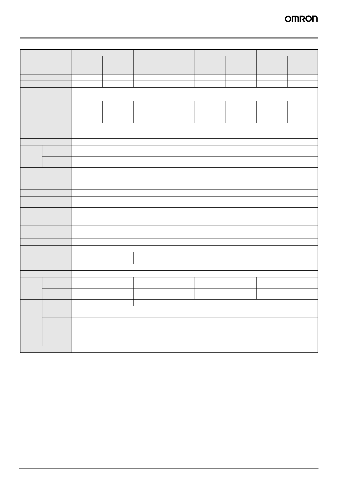
E2E
E2E-X@D@ DC 2-wire Models
Size M8 M12 M18 M30
Type Shielded Unshielded Shielded Unshielded Shielded Unshielded Shielded Unshielded
Item E2E-X2D@ E2E-X4MD@ E2E-X3D@ E2E-X8MD@ E2E-X7D@ E2E-
Sensing distance 2 mm ±10% 4 mm ±10% 3 mm ±10% 8 mm ±10% 7 mm ±10% 14 mm ±10% 10 mm ±10% 20 mm ±10%
Set distance
(See note 1.)
Differential travel 15% max. of sensing distance 10% max. of sensing distance
Sensing object Ferrous metal (The sensing distance decreases with non-ferrous met al, refer to Engineering Data.)
Standard sensing object Iron, 8 x 8 x
Response speed (See
note 2.)
Power supply voltage
(operating voltage
range)
Leakage current 0.8 mA max.
Control
output
Indicator D1 Models: Operation indicator (red LED), setting indicator (green LED)
Operation mode
(with sensing object approaching)
Diagnostic output delay 0.3 to 1 s
Protection circuits Surge suppressor, output load short-circuit pro tection (for control and diagnostic output)
Ambient temperature Operating: –25° C to 70° C, Storage: –40° C to 85° C (with no icing or condensation)
Ambient humidity Operating/Storage: 35% to 95% (with no condensation)
Temperature influence ±15% max. of sensing dis-
Voltage influence ±1% max. of sensing distance in the rated voltage range ±15%
Insulation resistance 50 MΩ min. (at 500 VDC) between current-carrying parts and case
Dielectric strength 1,000 VAC at 50/60 Hz for 1 min between current-carrying parts and case
Vibration resistance 10 to 55 Hz, 1.5-mm double ampli tude for 2 hours each in X, Y, and Z directi ons
Shock resistance
Degree of protection IEC 60529 IP67 (Pre-wired model s, pre-wired connector models: JEM standard IP67g (waterproof and oil-proof))
Connection method Pre-wired models (standard length: 2 m), connector models, pre-wired connector models (standard length: 0.3 m)
Weight
(packed
state)
Material Case Stainless steel (SUS303) Brass-nickel plated
Accessories Instruction manual
Note: 1. Use the E2E within the range in which the setting indicator (green LED) is ON (except D2 models).
Load current
Residual
voltage
(See note
3.)
Pre-wired
models
Pre-wired
connector
models
Connector
models
Sensing
surface
Cable PVC (polyvinyl chloride)
Clamping
nuts
Toothed
washer
2. The response speed is an average value. Measurement conditions are as follows: standard sensing object, a distance of twice the standard sensing object,
and a set distance of half the sensing distance.
3. The residual voltage of each E2E model with the model number suffix “-M1J-T” is 5 V. When connecting an E2E model with the suffix “-M1J-T” to a device,
make sure that the device can withstand the residual voltage.
0 to 1.6 mm 0 to 3.2 mm 0 to 2.4 mm 0 to 6.4 mm 0 to 5.6 mm 0 to 11.2 mm 0 to 8.0 mm 0 to 16.0 mm
1mm
1.5 kHz 1.0 kHz 1.0 kHz 0.8 kHz 0.5 kHz 0.4 kHz 0.4 kHz 0.1 kHz
12 to 24 VDC (10 to 30 VDC), ripple (p-p): 10% max.
3 to 100 mA
Diagnostic output: 50 mA for -D1(5)S mod els
3 V max. (Load current: 100 mA, Cable length: 2 m. M1J-T models only: 5 V max.)
D2 Models: Operation indicator (red LED)
D1 Models: NO
D2 Models: NC
For details, refer to Timing Charts.
tance at 23° C in the temperature range of –25° C to 70° C
500 m/s2 10 times each in X,
Y, and Z directions
Approx. 60 g Approx. 70 g Approx. 130 g Approx. 175 g
--- Approx. 40 g Approx. 70 g Approx. 110 g
Approx. 15 g Approx. 25 g Approx. 40 g Approx. 90 g
PBT (polybutylene terephthala te)
all E2E-@@@-U PUR/PE (polyurethane /po lyethylene)
Brass-nickel plated
Iron-zinc plated
Iron, 20 x 20 x
1mm
Iron,12 x 12 x
1mm
±10% max. of sensing di stance at 23° C in the temperature range of –25° C to 70° C
1,000 m/s2 10 times each in X, Y, and Z directions
Iron,30 x 30 x
1mm
Iron, 18 x 18 x
1mm
X14MD@
Iron, 30 x 30 x
1mm
E2E-X10D@ E2E-
Iron,30 x 30 x
1mm
X20MD@
Iron, 54 x 54 x
1mm
5E2E
E2E-X@E@/F@ DC 3-wire Models
Size M8 M12 M18 M30
Type Shielded Unshielded Shielded Unshielded Shielded Unshielded Shielded Unshielded
Item E2E-X1R5E@/F@E2E-X2ME@/ F@E2E-X2E@/ F@E2E-X5ME@/F@E2E-X5E@/
Sensing distance 1.5 mm ±10% 2 mm ±10% 2 mm ±10% 5 mm ±10% 5 mm ±10% 10 mm ±10% 10 mm ±10% 18 mm ±10%
Set distance 0 to 1.2 mm 0 to 1.6 mm 0 to 1.6 mm 0 to 4.0 mm 0 to 4. 0 mm 0 to 8.0 mm 0 to 8.0 mm 0 to 14.0 mm
Differential travel 10% max. of sensing distance
Sensing object Ferrous metal (The sensing distance decreases with non-ferrous metal, refer to Engineering Data.)
Standard sensing ob-
ject
Response speed (See
note 1.)
Power supply voltage
(operating voltage
range) (See note 2.)
Current consumption 13 mA max.
Control
output
Indicator Operation indicator (red LED)
Operation mode
(with sensing object approaching)
Protection circuits Power supply reverse polarity pro tection, surge suppressor, output lo ad sho rt- circuit protection
Ambient temperature
(See note 2)
Ambient humidity Operating/Storage: 35% to 95% (with no icing)
Temperature influence ±15% max. of sensing distance at 23° C in the temperature range of –40 °C to 85° C
Voltage influence ±1% max. of sensing distance in the rated voltage range ±15%
Insulation resistance 50 MΩ min. (at 500 VDC) between current-carrying parts and case
Dielectric strength 1,000 VAC at 50/60 Hz for 1 min between current-carrying parts and case
Vibration resistance 10 to 55 Hz, 1.5-mm double amplitude for 2 hours each in X, Y, and Z directions
Shock resistance
Degree of protection IEC 60529 IP67 (Pre-wired models: JEM standard IP67g ( w aterproof and oil-proof))
Connection method Pre-wired models (sta ndard length 2 m), connector models
Weight
(packed
state)
Material Case Stainless steel (SUS303) Brass-nickel plated
Accessories Instruction manual
Load current
(See note 2.)
Residual
voltage
Pre-wired
models
Connector
models
Sensing surface
Cable PVC (polyvinyl chloride)
Clamping
nuts
Toothed
washer
Iron, 8 x 8 x
1mm
2.0 kHz 0.8 kHz 1.5 kHz 0.4 kHz 0.6 kHz 0.2 kHz 0.4 kHz 0.1 kHz
12 to 24 VDC (10 to 40 VDC), ripple (p-p): 10% max.
200 mA max.
2 V max. (Load current : 200 mA, Cable len gth: 2 m)
E1 F1 Models: NO
E2 F2 Models: NC
For details, refer to Timing Charts.
Operating/Storage: –40° C to 85° C (with no icing or condens ation)
±10% max. of sensing distance at 23° C in the temperature range of –25 °C to 70° C
500 m/s2 10 times each in X, Y,
and Z directions
Approx. 65 g Approx. 75 g Approx. 150 g Approx. 195 g
Approx. 15 g Approx. 25 g Approx. 40 g Approx. 90 g
PBT (
polybutylene terephthalate)
Brass-nickel plated
Iron-zinc plated
Iron, 12 x 12 x
1mm
Iron, 12 x 12 x
1mm
1,000 m/s2 10 times each in X, Y, and Z directions
Iron, 15 x 15 x
1mm
F@
Iron, 18 x 18 x
1mm
E2E-X10ME@/
F@
Iron, 30 x 30 x
1mm
E2E-X10E@/
F@
Iron, 30 x 30 x
1mm
E2E-X18ME@/
F@
Iron, 54 x 54 x
1mm
Note: 1. The response speed is an average value. Measurement conditions are as follows: standard sensing object, a distance of twice the standard sensing object,
and a set distance of half the sensing distance.
2. When using an E2E with an M8 connector at an ambient temperature range between 70° C and 85° C, supply 10 to 30 VDC to the E2E and make sure that
the E2E has a control output of 100 mA maximum.
6 Inductive Sensors

E2E-X@Y@ AC 2-wire Models
Size M8 M12 M18 M30
Unshielded
Shielded
E2E-X2MY@ E2E-X2Y@ E2E-X5MY@ E2E-X5Y@
Item
Type Shielded
E2E-X1R5Y@
Sensing distance 1.5 mm ±10% 2 mm ±10% 2 mm ±10% 5 mm ±10% 5 mm ±10% 10 mm ±10% 10 mm ±10% 18 mm ±10%
Set distance 0 to 1.2 mm 0 to 1.6 mm 0 to 1.6 mm 0 to 4.0 mm 0 to 4.0 mm 0 to 8.0 mm 0 to 8.0 mm 0 to 14.0 mm
Differential travel 10% max. of sensing distance
Sensing object Ferrous metal (The sensing distance decreases with non-ferrous metal, refer to Engineering Data.)
Standard sensing
object
Iron, 8 x 8 x
1mm
Iron,12 x 12 x
1mm
Iron, 12 x 12 x
1mm
Response speed 25 Hz
Power supply volt-
age (operating voltage range)
(See note 1.)
24 to 240 VAC, 50/60 Hz (20 to 264 VAC)
Leakage current 1.7 mA max.
Control
output
Load current (See
note 2.)
Residual
voltage
5 to 100 mA 5 to 200 mA 5 to 300 mA
Refer to Engineering Data.
Indicator Operation indicator (red LED)
Operation mode
(with sensing object
approaching)
Y1 Models: NO
Y2 Models: NC
For details, refer to Timing Charts.
Protection circuit Surge suppressor
Ambient temperature
(See notes 1 and 2.)
Operating/Storage: –25° C to
70° C (with no icing or con-
Operating/Storage: –40° C to 85°C (with no icing or condensation)
densation)
Ambient humidity Operating/Storage: 35% to 95% (with no condensation)
Temperature influ-
ence
±10% max. of sensing distance at 23° C in the temperature range of –25° C to
±15% max. of sensing distance at 23° C in the temperature range of –40° C to 85° C
±10% max. of sensing distance at 23° C in the temperature range of –25° C to 70° C
70° C
Voltage influence ±1% max. of sensing distance in the rated voltage range ±15%
Insulation resistance 50 MΩ min. (at 500 VDC) between current-carrying parts and case
Dielectric strength 4,000 VAC at 50/60 Hz for 1 min between current-carrying parts and case (2,000 VAC for M8 Models)
Vibration resistance 10 to 55 Hz, 1.5-mm double amplitude for 2 hours each in X, Y, and Z directions
Shock resistance
2
500 m/s
Y, and Z directions
10 times each in X,
1,000 m/s2 10 times each in X, Y, and Z directions
Degree of protection IEC 60529 IP67 (Pre-wired models: JEM standard IP67g (waterproof, oil-proof))
Connection method Pre-wired models (standard length 2 m), connector models
Weight
(packed
state)
Pre-wired
models
Connector
Approx. 60 g Approx. 70 g Approx. 130 g Approx. 175 g
Approx. 15 g Approx. 25 g Approx. 40 g Approx. 90 g
models
Material Case Stainless steel (SUS303) Brass-nickel plated
Sensing
surface
Cable PVC (polyvinyl chloride)
Clamping
nuts
Toothed
washer
PBT (polybutylene terephthalate)
Brass-nickel plated
Iron-zinc plated
Accessories Instruction manual
Unshielded
Iron, 15 x 15 x
1mm
Shielded
Iron, 18 x 18 x
1mm
Unshielded
E2E-X10MY@
Iron, 30 x 30 x
1mm
Shielded
E2E-X10Y@
Iron, 30 x 30 x
1mm
Unshielded
E2E-X18MY@
Iron, 54 x 54 x
1mm
Note: 1. When supplying 24 VAC to any of the above models, make sure that the operating ambient temperature range is over –25° C.
2. When using an M18-or M30-sized E2E within an ambient temperature of 70° C to 85° C, make sure that the E2E has a control output of 5 to 200 mA max.
7E2E
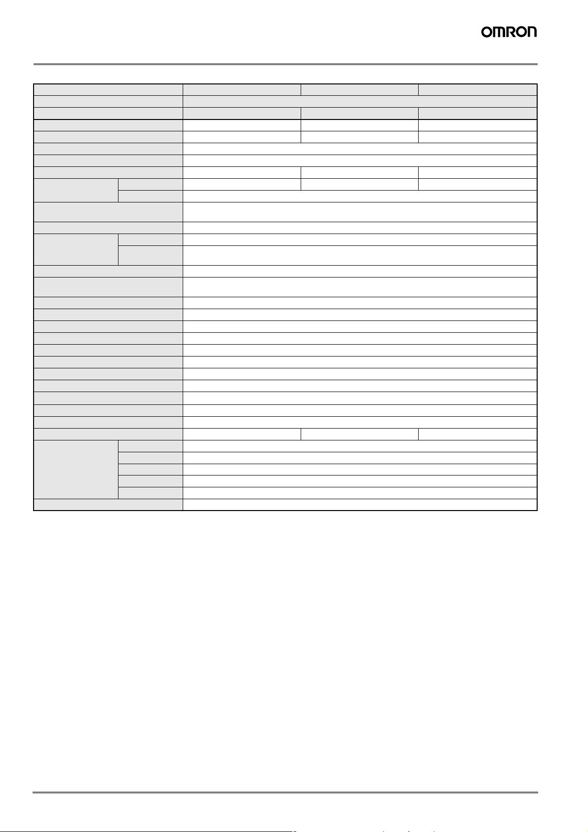
AC/DC 2-wire Models
Size M12 M18 M30
Type Shielded
Item E2E-X3T1 E2E-X7T1 E2E-X10T1
Sensing distance 3 mm ±10% 7 mm ±10% 10 mm ±10%
Set distance 0 to 2.4 mm 0 to 5.6 mm 0 to 8.0 mm
Differential travel 10% max. of sensing distance
Sensing object Ferrous metal (The sensing distance decreases with non-ferrous metal, refer to Engineering Data.)
Standard sensing object Iron, 12 x 12 x 1 mm Iron, 18 x 18 x 1 mm Iron, 30 x 30 x 1 mm
Response speed
(See note 1.)
Power supply voltage
(operating voltage range) (See note 2.)
Leakage current 1 mA DC max., 2 mA AC max.
Control output Load current 5 to 100 mA
Indicator Operation indicator (red LED), setting indicator (green LED)
Operation mode
(with sensing object approaching)
Protection circuits Output load short-circuit protection (at 20 to 40 VDC), Surge suppressor
Ambient temperature Operating: –25° C to 70° C, Storage: –40° C to 85° C (with no icing or condensation)
Ambient humidity Operating/Storage: 35% to 95% (with no condensation)
Temperature influence ±10% max. of sensing distance at 23° C in the temperature range of –25° C to 70° C
Voltage influence ±1% max. of sensing distance in the rated voltage range ±15%
Insulation resistance 50 MΩ min. (at 500 VDC) between current-carrying parts and case
Dielectric strength 4,000 VAC at 50/60 Hz for 1 min between current-carrying parts and case
Vibration resistance 10 to 55 Hz, 1.5-mm double amplitude for 2 hours each in X, Y, and Z directions
Shock resistance
Degree of protection IEC 60529 IP67 (JEM standard IP67g (waterproof, oil-proof))
Connection method Pre-wired Models (standard length 2 m)
Weight (packed state) Approx. 80 g Approx. 140 g Approx. 190 g
Material Case Brass-nickel plated
Accessories Instruction manual
DC 1.0 kHz 0.5 kHz 0.4 kHz
AC 25 Hz
24 to 240 VDC (20 to 264 VDC)/48 to 240 VAC (40 to 264 VAC)
Residual voltage
6.0 VDC max. (Load current: 100 mA, Cable length: 2 m)
10 VAC max. (Load current: 5 mA , Cable length: 2 m)
NO
For details, refer to Timing Charts.
1,000 m/s
2
10 times each in X, Y, and Z directions
Sensing surface PBT (polybutylene terephthalate)
Cable PVC (polyvinyl chloride)
Clamping nuts Brass-nickel plated
Toothed washer Iron-zinc plated
Note: 1. The response speed is an average value. Measurement conditions are as follows: standard sensing object, a distance of twice the standard sensing object,
and a set distance of half the sensing distance.
2. Power supply voltage waveform: Use a sine wave for the power supply. Using a rectangular AC power supply may result in faulty reset.
8 Inductive Sensors
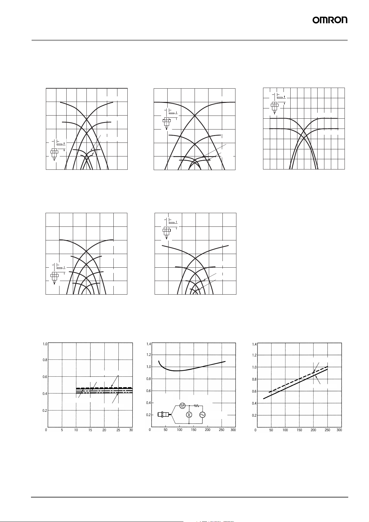
Engineering Data
(mm)
)
E2E
Operating Range (Typical)
Shielded Models
E2E-X@D@
E2E-X@T1
12
10
8
6
Y
4
Sensing distance X (mm)
2
0
−20 −15 −10 −5 0 5 10 15 20
X
E2E-X10
E2E-X7
E2E-X3
E2E-X2
DistanceY (mm)
Unshielded Models
E2E-X@MD@ E2E-X@ME@/F@
30
25
E2E-X@E@/F@
E2E-X@Y@
12
10
8
6
4
Sensing distance X (mm)
2
0
−15 −10 −5 0 5 10 15
E2E-X@MY@
30
25
E2E-C@C@/B@
E2E-X@C@/B@
1.6
E2E-X10
Y
X
E2E-X5
E2E-X2
E2E
-X1R5
Distance Y (mm)
Y
X
1.4
1.2
1.0
0.8
0.6
0.4
Sensing distance X (mm)
0.2
0
−3.0 −2.0 −1.0 0 1.0 2.0 3.0
Y
X
E2E-X1/E2E-C1
E2E-CR8
Distance Y (mm)
20
15
10
Sensing distance X (mm)
Y
X
5
0
−30 −20 −10 0 10 20 30
E2E-X14M
E2E-X8M
E2E-X4M
Distance Y (mm)
E2E-X20M
20
15
10
Sensing distance X (mm)
5
0
−30 −20 −10 0 10 20 30
E2E-X18M
E2E-X10M
E2E-X5M
E2E-X2M
Distance Y
Leakage Current (Typical)
E2E-X@D@ E2E-X@Y@ E2E-X@T1
E2E-X10D1-N
E2E-X3D1-N
E2E-X2D1-N
Leakage current (mA)
E2E-X7D1-N
Proximity
Sensor
(when
OFF)
Leakage current (mA)
Protective
resistance
AC power
supply
DC/AC
Leakage current (mA)
AC power supply
DC power supply
Supply voltage (V)
Supply voltage (V)
Supply voltage (V
9E2E
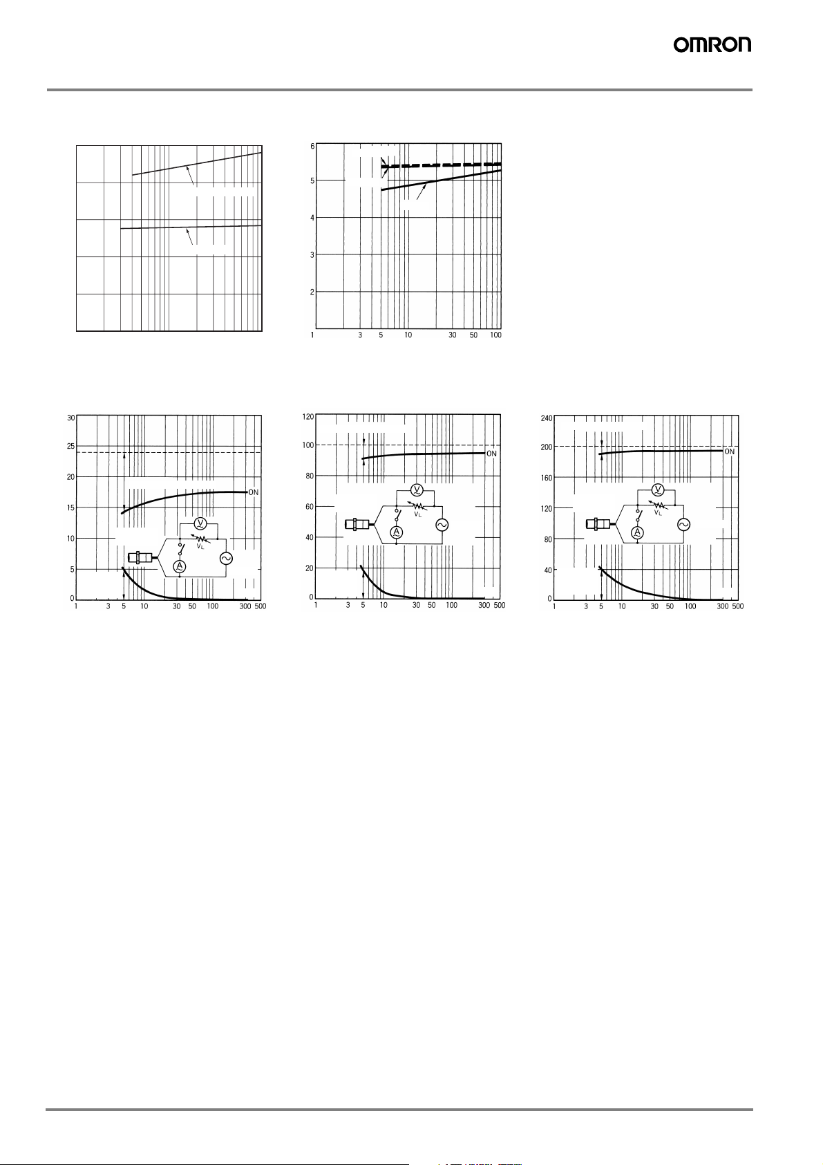
Residual Output Voltage (Typical)
(mA)
)
)
E2E-X@D@
5
E2E-X@T1
200 VAC
4
3
2
1
Residual output voltage (V)
0
1 3 5 10 30 50 100
E2E-X@D1-M1J-T
E2E-X@D@
Load current (mA)
E2E-X@Y@
24 VAC
Residual output voltage
Residual
load
voltage
Proximity
Sensor
Load voltage VL (V)
24 VAC
OFF
Residual output voltage (V)
100 VAC
Residual output voltage
Load voltage VL (V)
Residual
load
voltage
100 VAC
Load current (mA)
Proximity
Sensor
24 VDC
100 VAC
OFF
200 VAC
Residual output voltage
L (V)
Load voltage V
Residual
load
voltage
Proximity
Sensor
200 VAC
OFF
Load current
Load current (mA
Load current (mA
10 Inductive Sensors
 Loading...