

(2/2)
Type
Connection method
Supply voltage
Power consumption
Control output
Timer
Timer time
Differential detection mode
Fine positioning
Mutual interference
prevention
I/O settings
Response time
Advanced, twin-output models
Prewired
E2C-EDA11
E2C-EDA41
Separate
connector
*
1
E2C-EDA6
E2C-EDA8
Advanced, external-input models
Communication unit
connection model *3
E2C-EDA0
ー
ー
Output setting (channel 2 output,
area output, self diagnosis output,
or disconnection output)
External input setting (teaching
method, fine positioning, zero reset,
or synchronous detection)
Output setting
(2CH output)/area output
/self-diagnosis output)
Prewired
E2C-EDA21
E2C-EDA51
Separate
connector
*
1
E2C-EDA7
E2C-EDA9
12 to 24 VDC±10% ripple(p-p) 10%max.
NPN
PNP
1,080mW max. (45mA max. at 24 VDC)
Open collector (26.4 VDC max.);
Load current: 50mA max.; residual voltage: 1 V max.
OFF, OFF-delay, or one-shot
1 ms to 5 s
Supported
Supported
Supported (intermittent oscillation system)
*2
response time = (number of Amplifier Units + 1)×15 ms
The number of setting : 2 to 5
Power supply
connector
Protector seal
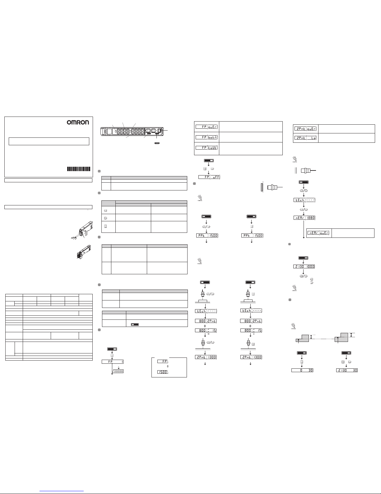
Setting the Mode
Key Operations
Reading Displays
SET
Mode
Main display (red)
Sub-display (green)
RUN
(See note.)
SET Select to set detection conditions, to teach the threshold value, to set initializing, etc.
Mode Description
RUN
Note: The information that appears on the displays can be set using the display switch
function. Refer to 5. Detailed Settings.
Note: Refer to 4.Basic settings for the setting method.
UP key Increases the threshold. Depends on the setting.
・Executes teaching.
・Changes the setting forward.
Depends on the setting.
・Executes teaching.
・Changes the setting in reverse.
Decreases the threshold.
Depends in the MODE key setting (See note.)
・
Executes positioning teaching(default setting).
・
Teaching with and without a workpiece.
・Executes fine positioning.
・Executes a zero reset.
Switches the function to be set on the
display.
DOWN key
MODE key
Key
Function
RUN mode SET mode
NO NC
Adjusting the sensitivity (as Required)
1
2
Setting the Operation Mode
●The setting method depends on the type of Amplifier Unit.
Twin-output model
Type Setting method
External-input model
NO(normally-open)
(default)
Selection Description
NC(normally-close)
RUNSET
Switch to RUN mode.
Tuning completed and previous display returns.
Main Display
Press the MODE key for at
least 3 seconds.
Fine positioning target value
FP
During fine
positioning
Progress bar
FP
Display alternates
at a fixed interval.
① Lit when the output is ON.
Twin-output Models: Lit when the output for channel 1 is ON.
② Displays the detection level or the function name.
③ Twin-output Models: Lit when the output for channel 2 is ON.
External-input Models: Lit when fine positioning is set.
④ Displays supplemental detection information, the setting of a function, etc.
⑤ Used to switch the mode.
⑥ Twin-output Models: Used to select the channel to display or set.
External-input Models: Used to select normally-open or normally-close operation
⑦ Used to change the display, set functions, etc.
●
Setting Errors
An error has occurred if one of the following display appears the progress bar is displayed.
Over Error
FP OVER
Switch to RUN mode
Bottom Error
FP BOTM
FP OFF
RUNSET
Flashes twice
Flashes twice
Timeout Error
FP TOUT
Flashes twice
+
Threshold
value
NEAR
TECH
----
Setting Thresholds
●Setting Errors
Switch to SET mode.
NEAR OVER
RUNSET
The sub-display will flash.
Teaching completed and previous display returns.
③No-workpiece Teaching
The threshold value that was set will flash twice.
Do one of the following and then repeat the operation
・Adjust the Head to decrease the detection level.
・Execute fine positioning.
Press the UP or DOWN key.
Press the UP or DOWN key for at least 3 seconds.
A detection level and a detection margin value are displayed.
3
5
When the UP or DOWN key is pressed to change the threshold value, the threshold
value will be displayed on the sub-display regardless of the display switch setting.
The information set for the display switch setting will return approximately 5 seconds
after the threshold is changed.
If DIFF (differential operation) is set for the detection method, the threshold value
will be set to half of the difference between the two measured values.
Threshold
value
Threshold
value
2PNT
TECH
Detection
level
Detection
level
----
Detection
margin value
Detection
margin value
4
The information set for the display switch will be displayed.
(The default setting is for the detection level and the threshold value.)
Sensor head
ON point
Sensor head
Without a workpiece
Detection
level
Threshold
value
Adjust the threshold value with the UP and DOWN keys.
Increases the threshold value.
Decreases the threshold value.
Switch to SET
mode.
RUNSET
The sub-display
will flash.
②Teaching With and Without a Workpiece
①Positioning Teaching
Position a workpiece
and press the
UP or DOWN key.
Switch to RUN mode.
RUNSET
Manually Setting Threshold Values
PPT
Threshold
value
Switch to SET
mode.
RUNSET
The threshold
value that was set
will flash twice.
Teaching completed and
previous display returns.
Press the UP or DOWN
key for at least 3 seconds.
Please observe the following precautions for safe use of the product.
1) Do not use the Amplifier Unit in environments subject to flammable or explosive gases.
2) Do not use the Amplifier Unit in environments subject to exposure to water, oil, chemicals, etc.
3)
Do not attempt to disassemble, repair, or modify the Amplifier Unit in any way.
4) Do not apply voltages or currents that exceed the rated ranges.
5) Wire the Amplifier Unit correctly, e.g., do not reverse the polarity of the power supply.
6) Connect the load correctly.
7) Do not short both ends of the load.
8) Do not use the Amplifier Unit if the case is damaged.
9) When disposing of the Amplifier Unit, treat it as industrial waste.
1. Ratings and Specifications
3. Basic Operating Information
Please observe the following precautions to prevent failure to operate, malfunction, or undesirable
effects on product performance.
1) Wire the Amplifier Unit separately from power supply or high-voltage lines. If the Amplifier Unit
wiring is wired together with or placed in the same duct as high-power lines, inductive noise may
cause operating errors or damage the Amplifier Unit.
2)
Do not extend the cable to more than 30 m, and use a wire size of 0.3 mm2 or larger for the extension cable.
3)
The Amplifier Unit is ready to operate 200 ms after the power supply is turned ON. If the Amplifier Unit and load are
connected to power supplies separately, turn ON the power supply to the Amplifier Unit first.
Please turn on the power supply at the same time when you connecting use the Amplifier Units with cables.
Mutual interference prevention might not operate normally or mobile console might not be able to be used
when the difference between connected Amplifiers at the power supply turning or time is 30ms or more.
4) Always keep the protective cover in place when using the Amplifier Unit.
5)
When using a connector model, place a protective label (provided with the E3X-CN series connectors) on
the power supply connecting terminals that are not used, to prevent electric shock or short circuit.
6)
When using a communication unit connection model, place a protective cap
(provided with the E3X-ECT/CRT communication unit ) on the connecting
terminals that are not used, to prevent electric shock or short circuit.
7) When connecting or removing the communication unit connection
model, make sure that the connecting part is not slanted.
8)
Always turn OFF the power supply before connecting or disconnecting Sensor
Heads, joining or separating Amplifier Units, or adding Amplifier Units.
9)
If the data is not written to the EEPROM correctly due to a power failure or
static-electric noise, initialize the settings using the keys on the Amplifier Unit.
10) Using a Mobile Console(The communication unit connection
model cannot use a mobile console.)
Use the E3X-MC11-SV2 Mobile Console for the E2C-EDA-series Amplifier Units. Other Mobile
Consoles, such as the E3X-MC11,E3X-MC11-S, cannot be used.
11) Optical communications are not possible with an E3X-DA-N Amplifier Unit.
12)
Depending on the application environment, time may be required for the detection level to stabilize after the power supply is turned ON.
13) Output pulses may occur when the power is interrupted and so turn OFF the power to the load or
load line before turning OFF the power to the Sensor.
14) The Sensor Head of E3C-LDA cannot be used. It may damage, if it connects.
15)
When mutual interference prevention is confirmed, the execution time of fine positioning becomes long.
16) Do not use thinners, benzine, acetone, or kerosene for cleaning the Amplifier Unit.
17)
A disconnection output may be rarely outputted under the large installation conditions of a detection level also except disconnection.
■ Confirming the Package Contents
・Amplifier Unit: 1 ・ Instruction Sheet (this sheet): 1
Refer to 5.Detailed Settings Detection Method
Operation/Storage: 35 to 85 %RH (with no condensation)
10 to 55 Hz, 1.5mm double amplitude 2 hours each in X, Y, and Z directions
The mode is set using the SET/RUN switch. Set this switch according to the operation to be performed.
Teaching is performed in the state where a workpiece is in an ON
point. A detection level is set up as a threshold value.
Teaching is performed in the state where there is no workpiece.
It sets up about +6% of a detection level as a threshold value. It is stabilized and a very small
difference can be detected.
If DIFF(differential operation) is set for the detection method, the threshold value will be set
to the minimum value above the detection level without a workpiece that will enable stable
detection.
Teaching can be performed twice, once with and once without a workpiece, and the value between
the two measured values is set as the threshold.
In the case of a 【Method 2】, please check that a setup of a "MODE key setting" function is
[2PNT](teaching with and without a workpiece) in advance. Refer to 5.Detailed Settings.
The operation keys are used to switch the displays and set detection conditions. The functions of the
keys depend on the current mode.
The information displayed on the main display and sub-display depends on the current mode. For the
default settings, the RUN mode displays will appear when the power supply is turned ON for the first time.
Select either normally-open or normally-close operation.
Fine positioning can be used to adjust the detection level that is currently being received to the fine
positioning target value (1,500). Before executes fine positioning, always secure the workpiece and
Sensor Head and be sure that the detection level is stable.
Confirm that the MODE key setting is FP(fine positioning) in advance.
The default is "PPT" (positioning teaching). Refer to 5. Detailed Settings.
Teaching cannot be performed when DIFF(differential operation) is set as the detection
method.
4. Basic Settings
The output will turn ON when the detection level is above the threshold.
If DIFF (differential operation) is set for the detection method, the output will turn
ON when an edge is detected.
Set as the operation mode in SET mode.
Refer to 5. Detailed Settings.
Set using the operation mode selector.
The output will turn ON when the detection level is below the threshold.
If DIFF (differential operation) is set for the detection method, the output will turn
OFF when an edge is detected.
●
Clearing method
【Method 1】 【Method 2】
【Method 1】 【Method 2】
PPT Threshold
value
Switch to RUN
mode.
RUNSET
The threshold
value that was set
will flash twice.
Teaching completed and
previous display returns.
Press the MODE key for
at least 3 seconds.
●
Setting method
●
Setting method
●
Setting method
●
Setting method
In the case of a 【Method 2】, please check that a setup of a "MODE key setting" function is
[PPT](positioning teaching) in advance. Refer to 5.Detailed Settings.
Workpiece
Workpiece
TECH ----
Switch to RUN
mode
RUNSET
2PNT
●
Setting method
A threshold value can be set manually.
A detection margin
level can check the
margin of the present
detection level to the
variation in a detection
level with a workpiece.
A detection margin
level can check the
margin of the present
detection level to the
variation in a detection
level with a workpiece.
Remove the
workpipece and
press the UP or
DOWN key.
The threshold
value that was set
will flash twice.
The threshold
value that was set
will flash twice.
Remove the
workpiece and
press the MODE
key for at least 3
seconds.
The sub-display will
flash.
Position a workpiece
and press the MODE
key for at least 3
seconds.
Teaching completed and
previous display returns.
Teaching completed and
previous display returns.
Display alternates
at a fixed interval.
Display alternates
at a fixed interval.
Groups of 1 to 2 Amplifiers: -10℃to 55℃ Groups of 3 to 5 Amplifiers: -10℃ to 50
℃
Groups of 6 to 16 Amplifiers: -10℃ to 45℃ Groups of 17 to 30 Amplifiers: −10°C to 40°C
Combination with EDR6-□
Groups of 3 to 4 Amplifiers: -10
℃
to 50℃ Groups of 5 to 8 Amplifiers: -10℃ to 45
℃
Groups of 9 to 16 Amplifiers: -10℃ to 40
℃
Groups of 17 to 30 Amplifiers: −10°C to 35°C
●
Setting Errors
An error has occurred if any of the following is display when the UP or DOWN key is pressed
without a workpiece.
Do one of the following and then repeat the operation
・Adjust the Head to decrease the detection level.
・Execute fine positioning.
Do one of the following and then repeat the operation
・Adjust the Head to increase the detection level.
・Execute fine positioning.
2PNT OVER
2PNT LO
Flashes twice
Flashes twice
Flashes twice
A zero point is registered. (zero reset)
Switch to RUN mode.
This level difference
is judged.
This level difference
is judged.
Zero reset execution Zero reset execution
Switch to RUN mode.
Zero reset is
cleared.
RUNSET RUNSET
+
Detection
level
Threshold
value
Detection
level
Threshold
value
Zero reset cannot be performed when DIFF(differential operation) is set as the
detection method.
The standard position of a workpiece is registered as "detection level =0", and it judges to the amount of
change of a detection level.When there is change of the standard position of a workpiece or change of
the detection level by the operating condition, detection stabilized when performing zero reset can be
performed.
Execution of zero reset shifts to "0" the detection level currently displayed on the main display. The
threshold value currently displayed on the sub display is not shifted.
Please set "a MODE key settings" as "0RST" in advance. The default is "PPT" (positioning teaching).
Refer to 5.Detailed Settings.
●
Setting method
●
Clearing method
Workpiece Next workpiece
©
OMRON Corporation 2004 All Rights Reserved.
INSTRUCTION SHEET
Proximity Sensors with Separate Digital Amplifier
Amplifier Units
E2C-EDA
□□
PRECAUTIONS FOR SAFE USE
PRECAUTIONS FOR CORRECT USE
Operation
Storage
Model
number
Ambient
temperature
Displays the detection level,* function name,
or other information depending on the key
operation.
*The detection level will be displayed even if
DIFF (differential operation) is set for the
detection method.
For the default setting, the current
detection level will be displayed.
The change in the detection level will be
displayed when DIFF (differential
operation) is set for the detection mode.
Displays threshold value* or the setting of the
function displayed on the main display depending
on the key operation.
*The threshold value for the change in the
detection level will be displayed if DIFF (differential
operation) is set for the detection method.
For the default setting, the current threshold
value will be displayed.
The threshold value for the change in the
detection level will be displayed if DIFF
(differential operation) is set for the detection
method.
A progress bar will appear
on the sub-display one
digit at a time.(Release the
MODE key when the
progress bar appears.)
It is the error for the present workpiece position having been too far to the
fine positioning possible range. It is adjusted by the maximum sensitivity.
The fine positioning possible range is 50 to 150% of measurement range.
It is the error for the present workpiece position having been too near to the
fine positioning possible range. It is adjusted by the minimum sensitivity. The
fine positioning possible range is 50 to 150% of measurement range.
An error occurred because the detection level was not stable during fine
positioning.
Make sure that the workpiece and Sensor Head are secured and retune
the sensitivity.
Hold down the MODE key and press the DOWN key for at least 3 seconds.
Note: Press the DOWN key right after pressing the MODE key.
The sub-display will flash twice and fine positioning will be cleared.
Press the MODE key for at
least 3 seconds.
The display of a detection
level is fixed.
The DOWN key is pushed 3
seconds or more, pushing
the MODE key. Press the
DOWN key right after
pressing the MODE key.
Zero reset is
performed and a
detection level is
shifted to "0."
UP
SET RUN
1 2
DOWN MODE
NO NC
①Operation indicator
E2C
③Twin-output Models : Operation indicator for channel 2
External-input Models : Fine positioning indicator
⑥Twin-output Models : Channel selector
External-input Models : Operation mode selector
②Main display (red)
④Sub-display (green)
⑦Operation keys
⑤SET/RUN switch
2. Nomenclature
*1: When using individually or as a master, obtain the E3X-CN21 Master Connector (4-conductor), and when
using as a slave, obtain the E3X-CN22 Slave Connector (2-conductor). Either Connector can be used.
*2: Communications are disabled if SHS is selected for the detection mode, and the communications functions
for mutual interference prevention and the Mobile Console will not function.
*3: Connectable communication units are E3X-ECT (30 units max.) and E3X-CRT (16 units max.). For details
on names of each part and settings, refer to items of the twin output model.
−20℃
to 70
℃(withnoicingorcondensation)
Ambient humidity
Vibration
Select for actual detection operation or set the following: Manual adjustment of
thresholds, Positioning teaching, Teaching with and without a workpiece, Fine
positioning, Zero reset, or Key lock
The following notice applies only to products that carry the CE mark:
Notice:
This is a class A product. In residential areas it may cause radio
interference, in which case the user may be required to take adequate
measures to reduce interference.
Manufacturer:
Omron Corporation,
Shiokoji Horikawa, Shimogyo-ku,
Kyoto 600-8530 JAPAN
Ayabe Factory
3-2 Narutani, Nakayama-cho,
Ayabe-shi, Kyoto 623-0105 JAPAN
TRACEABILITY INFORMATION:
Representative in EU:
Omron Europe B.V.
Wegalaan 67-69
2132 JD Hoofddorp,
The Netherlands
Protective Cap
Power Supply
Connecting Terminal
* 4 0 1 2 1 3 3 - 6 A *
RUNSET
Teaching (Detection levels/Threshold display)
NO(normally-open)
NO
NC
NC(normally-close)
Single edge
Either the rising or falling
edge is detected.
Double edge
Both the rising and falling
edge are detected.
Detection level Threshold value
Threshold value
The detection level
and threshold value
Timer disabled
----
OFFD
OFF-delay timer
ON-D
ON-delay timer
1SHT
One-shot timer
300μs 500μs
500μs 1ms
1ms 2ms
10ms 20ms
100ms 200ms
Single edge
This setting depends on the setting
for the differential edge selection.
Switch to SET mode.
Setting range: 1 to 5,000
Double edge
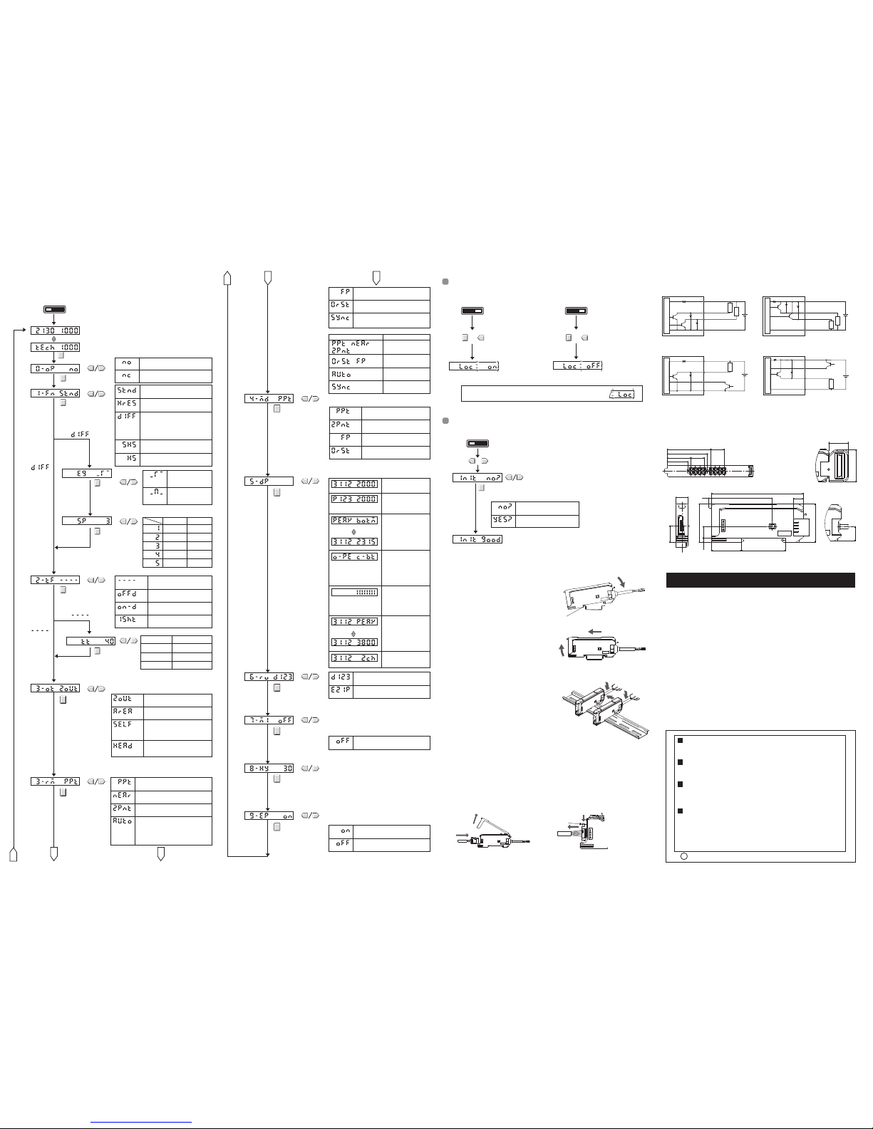
Standard mode
Response time: 1 ms
STND
HRES
High-resolution mode
Response time: 4 mss
DIFF
Not
SHS
Super-high-speed mode
Response time: 150μs
High-speed mode
Response time: 300μs
HS
Set separately for each channel for Twin-output Models.
2. Timer
5. Mode Key
Setting
6. Display Switch
7. Display
Orientation
9.
Hysteresis Setup
10. External Input
Memory
4. External Input
3. Twin Outputs
8.
Mutual Interference
Prevention
Number Set up
% detection level
O-PE C-BT
PEAK BOTM
Detection status
Peak level Bottom level
The following functions can be set in SET mode. The default settings are shown in the transition boxes
between functions.
For Twin-output Models, all settings except for the operation mode, timer settings and hysteresis setting
are the same for both channels.
*: The values shown for thresholds, detection levels, percentages, etc., are examples only. Actual
displays may vary.
The item that is controlled by the input from an external
device can be selected.
Normal display
D123
321D
Reversed display
Write results to EEPROM.
ON
OFF
Do not write results to EEPROM.
NEAR
Positioning teaching
PPT
No-workpiece teaching
2PNT
Teaching with and without a workpiece
Effective Pulse Widths
FP
Fine positioning
0RST
Zero reset
0.1s to 2s
Executing: 0.1 to 2s
Clearing: 3s or longer
Effective ON pulse
width: 0.1s min.
Detection response
time 500μs min.
Selection Pulse width
SYNC
Synchronous detection
The function is detected only while
the input is ON.
Executes a fine positioning
FP
0RST
Executes a teaching with and
without a workpiece
2PNT
Executes a positioning teaching
PPT
Executes a zero reset
The function of the MODE key in RUN mode can be
selected.
Output for each channel.
2OUT
AREA
Output if level is between the two
thresholds.
SELF
HEAD
(Twin-output Models Only)
(External-input Models Only)
Mutual interference prevention does
not work.
OFF
(External-input Models Only)
Detection level
Channel
The detection level and
channel number
The output for channel 1 functions according to the
detection mode selection.
,
,
Detection level
Detection level
PEAK
Peak level
Display alternates
at a fixed interval.
Display alternates
at a fixed interval.
A
B C
A
B
C
Switch to RUN mode.
Switch to RUN mode.
RUNSET
6. Convenient Functions
Initializing Settings
RUNSET
RUNSET
Initialization has been
completed.
Key Lock
NO?
YES?
Switch to SET mode.
+
+
+
LOC ON
LOC OFF
INIT
INIT GOOD
Hock on the Sensor Head connector end
DIN Track
DIN Track
1
2
1
1
2
1
2
(Unit: mm)
●
E2C-EDA11 and E2C-EDA6(NPN Models)●E2C-EDA41 and E2C-EDA8(PNP Models)
●
E2C-EDA21 and E2C-EDA7(NPN Models)●E2C-EDA51 and E2C-EDA9(PNP Models)
2.5 50.3
76
24.7
9.9
3.4
32
36.7
14
32
8.1
10
13.8
38.8
18.15
21.1
35.8
3.9×4=11.7
3.9×4=11.7
(Prewired Models)
The number of the amplifier which confirms mutual
interference prevention is set up.
Only the amplifier which wants to confirm mutual
interference prevention is made to connect, and it is
set as all amplifier.
After a setup should surely re-switch on a power supply.
The number of a setting: 2[2UT] to 5[5UT]
5. Detailed Settings
AUTO
All key operations can be disabled to help prevent key operating errors.
Only the operation keys are disabled. The switches and selectors will still function.
This procedure can be used to return all the settings to the original default values.
●
Setting Method
●
Setting Method
●
Clearing Method
●
Mounting Units
Catch the hook on the Sensor Head connector end
of the Unit on the DIN Track and then press down
on the other end of the Unit until it locks into place.
Always attach the Sensor Head connector end first.
If the incorrect end is attached first, the mounting
strength will be reduced.
●
Removing Units
Press the Unit in the direction indicated by "1"
and then lift up on the Sensor Head connector
end of the Unit in the direction indicated by
"2"
●
Mounting Amplifier Units in Group (Connector Type Models/Communication Unit
Connection Type Models)
Up to 16 connector type models can be connected. Up to 30 communication unit
connection type models can be connected to the communication unit
E3X-ECT, or 16 units to the E3X-CRT.
1. Mount the Amplifier Units one at a time onto the DIN Track.
2. Slide the Amplifier Units together and press the Amplifier
Units together until they click into place.
Secure the Units with an End Plate (PFP-M) if there is a
possibility of the Amplifier Units moving, e.g., due to vibration.
Reverse the above procedure to separate and remove the
Units. Do not attempt to remove Amplifier Units from the
DIN Track without separating them first.
7. Installing the Amplifier Unit
9. I/O Circuits
10. Dimensions
Lock button
1. Open the protective cover
2. A connector is turned so that a lock button may turn up,
and it inserts to the back.
To disconnect the Sensor Head, pull out the connector
while pressing on the lock button.
8. Connecting Sensor Heads
Display alternates
at a fixed interval.
Twin-output models can be set up for every channel.
Note: Refer to 4. Basic Settings for teaching methods.
Set separately for each channel.
0. Operation Mode
1.
Detection Method
Differential
Edge Selection
Differential
Response Time
(Twin-output Models only)
Differential operation mode
Operation is according to the change
in the detection level.
For Twin-output Models, the output for
channel 2 is always an alarm output
for the absolute detection level.
Not
Timer Time
1-ms increments1 to 20 ms
5-ms increments20 to 200 ms
100-ms increments200 ms to 1 s
1-s increments1 to 5 s
The function of the output for channel 2 can be selected.
This setting is not value if DIFF (differential operation)
is set for the detection method. (The output for channel
2 is always an alarm output for differential operation.)
Self-diagnosis output
Output when the detection level
is not stable, i.e., when the detection
level is ±10% of the threshold value
for 300 ms or longer.
Disconnection output
A disconnection output is outputted,
when the Sensor Head is
disconnected, or it does not connect.
Automatic teaching
The maximum and minimum detection
levels are sampled while the input is ON and,
when the input turns OFF, the average of these
values is set as the threshold value.
Disabled if the detection function is set to
"DIFF" (differential operation).
The information displayed in RUN mode can be selected.
When going to SET mode, this setting will be ignored and
the detection level and threshold value will be displayed.
The detection level as
a percentage of the
threshold value and the
threshold value.
The peak detection
level and bottom
detection level of fixed
time(2s).
The peak detection level
under detection, and the
bottom detection level in
un-detecting.
A display is updated when
detection-un-detecting
changes.
Analog bar display. The
current detection status is
displayed as an analog
bar. The bar will lengthen
from the right as ON
status is reached.
The current detection
level and the peak
detection level.
Hysteresis is set up.
Hysteresis is adjusted to perform the case where
the position of a workpiece is unstable, and finer
detection.
Adjustment range: 10 to 2000
Whether external input execution results are written
to EEPROM can be selected.
Disable this function if the external input is turned
ON
frequently. (The write life is approximately 100,000
writes.)
Hold down the MODE key and
press the UP key for at least 3
seconds. Press the UP key right
after pressing the MODE key.
Hold down the MODE key
and press the UP key for at
least 3 seconds. Press the
UP key right after pressing
the MODE key.
The sub-display will
flash twice and key
input will be disabled.
The sub-display will
flash twice and key
input will be enabled.
If a key is pressed while key operations are locked, "LOC" will flash
twice on the display to indicate that key operations have been disabled.
Press the UP or
DOWN key for at
least 3 seconds.
Press the MODE key at the
"
NO?" or "YES?" display.
Settings not initialized.
Settings initialized.
Internal circuits
Load
Load
12 to
24 VDC
Brown
Black
Orange
Blue
Internal circuits
Load
Load
12 to
24 VDC
Brown
Black
Orange
Blue
Internal circuits
Load
12 to
24 VDC
Brown
Black
Orange
External
input
Blue
Internal circuits
Load
12 to
24 VDC
Brown
Black
Orange
Blue
Output for
channel 1
Output for
channel 2
Output for
channel 1
Output for
channel 2
External
input
Control output
Control
output
12.50
(Communication Unit Connection Model)
31
19
*The E2C-EDA0 is a communication unit connection model.
OMRON Corporation
Suitability for Use
EUROPE
OMRON EUROPE B.V. Sensor Business Unit
Carl-Benz Str.4, D-71154 Nufringen Germany
Phone:49-7032-811-0 Fax: 49-7032-811-199
NORTH AMERICA
OMRON ELECTRONICS LLC
One Commerce Drive Schaumburg,IL 60173-5302 U.S.A.
Phone:1-847-843-7900 Fax : 1-847-843-7787
ASIA-PACIFIC
OMRON ASIA PACIFIC PTE. LTD.
No. 438A Alexandra Road #05-05-08(Lobby 2),
Alexandra Technopark, Singapore 119967
Phone : 65-6835-3011 Fax :65-6835-2711
o
THE PRODUCTS CONTAINED IN THIS SHEET ARE NOT SAFETY RATED.
THEY ARE NOT DESIGNED OR RATED FOR ENSURING SAFETY OF
PERSONS, AND SHOULD NOT BE RELIED UPON AS A SAFETY
COMPONENT OR PROTECTIVE DEVICE FOR SUCH PURPOSES.
Please refer to separate catalogs for OMRON's safety rated products.
OMRON shall not be responsible for conformity with any standards, codes, or
regulations that apply to the combination of the products in the customer's
application or use of the product.
Take all necessary steps to determine the suitability of the product for the
systems, machines, and equipment with which it will be used.
Know and observe all prohibitions of use applicable to this product.
NEVER USE THE PRODUCTS FOR AN APPLICATION INVOLVING
SERIOUS RISK TO LIFE OR PROPERTY WITHOUT ENSURING THAT THE
SYSTEM AS A WHOLE HAS BEEN DESIGNED TO ADDRESS THE RISKS,
AND THAT THE OMRON PRODUCT IS PROPERLY RATED AND
INSTALLED FOR THE INTENDED USE WITHIN THE OVERALL
EQUIPMENT OR SYSTEM.
See also Product catalog for Warranty and Limitation of Liability.
CHINA
OMRON(CHINA) CO., LTD.
Room 2211, Bank of China Tower,
200 Yin Cheng Zhong Road,
PuDong New Area, Shanghai, 200120, China
Phone : 86-21-5037-2222 Fax :86-21-5037-2200
OCT, 2009
D
 Loading...