

Omron DZ DATASHEET
Special-purpose Basic Switch
DZ
DPDT Basic Switch for Two Independent
Circuit Control
• Incorporates two completely independent built-in switches.
• Ideal for switching the circuits operating on two different voltages, and for controlling two independent circuits.
• Interchangeable with OMRON Z Basic Switches, as both
switches are identical in mounting hole dimensions, mounting
pitch and pin plunger position.
Model Number Structure
■ Model Number Legend
Limit
Switches
DZ-10G@-1@
1 2 3 4 5
1. Ratings
10: 10 A (250 VAC)
2. Contact Gap
G: 0.5 mm
3. Actuator
None: Pin plunger
V: Hinge lever
V22: Short hinge roller lever
V2: Hinge roller lever
W: Hinge lever
W22: Short hinge roller lever
W2: Hinge roller lever
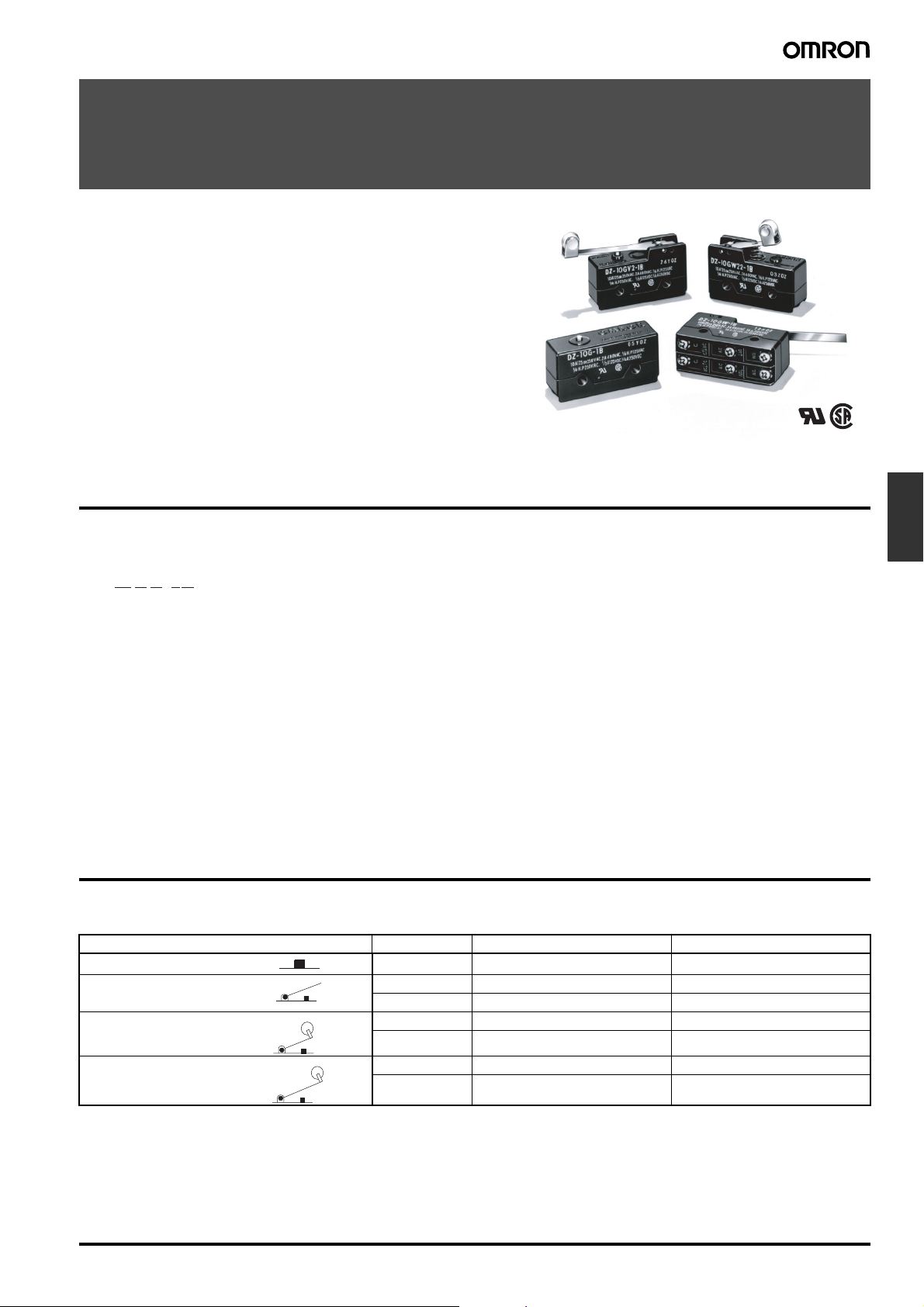
Ordering Information
■ List of Models
Actuator OT Solder terminal Screw terminal
Pin plunger
Hinge lever
Short hinge roller lever
Hinge roller lever
4. Contact Form
1: DPDT
5. Terminals
A: Solder terminal
B: Screw terminal
0.13 mm min. DZ-10G-1A DZ-10G-1B
1.6 mm min. DZ-10GW-1A DZ-10GW-1B
0.4 mm min. DZ-10GV-1A DZ-10GV-1B
0.9 mm min. DZ-10GW22-1A DZ-10GW22-1B
0.13 mm min. DZ-10GV22-1A DZ-10GV22-1B
1.2 mm min. DZ-10GW2-1A DZ-10GW2-1B
0.26 mm min. DZ-10GV2-1A DZ-10GV2-1B
Special-purpose Basic Switch DZ F-139
Specifications
■ Approved Standards ■ Approved Standard Ratings
Agency Standard File No.
UL UL508 E41515
CSA CSA C22.2 No. 55 LR21642
UL508 (File No. E41515)/
CSA C22.2 No. 55 (File No. LR21642)
Rated voltage DZ-10G
125 VAC 10 A 1/3 HP
250 VAC 10 A 1/4 HP
480 VAC 2 A
125 VDC 0.5 A
250 VDC 0.25 A
■ Ratings
Rated voltage Non-inductive load Inductive load Inrush current
Resistive load Lamp load Inductive load Motor load
NC NO NC NO NC NO NC NO NC NO
125 VAC
250 VAC
8 VDC
14 VDC
30 VDC
125 VAC 0.5 A 0.5 A 0.05 A 0.05 A
250 VDC 0.25 A 0.25 A 0.03 A 0.03 A
Note: 1. Inductive load has a power factor of 0.4 min. (AC) and a time constant of 7 ms max. (DC).
2. Lamp load has an inrush current of 10 times the steady-state current.
3. Motor load has an inrush current of 6 times the steady-state current.
10 A
10 A
10 A
10 A
10 A
2 A
1.5 A
3 A
3 A
3 A
1 A
0.7 A
1.5 A
1.5 A
1.5 A
6 A
4 A
6 A
6 A
4 A
3 A
2 A
5 A
5 A
3 A
1.5 A
1 A
2.5 A
2.5 A
1.5 A
30 A max. 15 A max.
■ Characteristics
Operating speed 0.1 mm to 1 m/s (at pin plunger)
Operating frequency Mechanical: 240 operations/min
Insulation resistance 100 MΩ min. (at 500 VDC)
Contact resistance 15 mΩ max. (initial value)
Dielectric strength 1,000 VAC, 50/60 Hz for 1 min between non-continuous terminals
Vibration resistance Malfunction: 10 to 55 Hz, 1.5-mm double amplitude
Shock resistance
Durability Mechanical: 1,000,000 operations min.
Ambient temperature Operating: −25°C to 80°C (with no icing)
Ambient humidity Operating: 35% to 85% max.
Weight Approx. 30 to 50 g
Note: 1. The values are for pin plunger models. (Contact your OMRON representative for other models.)
2. Malfunction: 1 ms max.
Electrical: 20 operations/min
1,500 VAC, 50/60 Hz for 1 min between current-carrying metal parts and non-current-carrying metal part,
and between current-carrying metal part and ground and between switches
2
Destruction: 1,000 m/s
Malfunction: 300 m/s
Electrical: 500,000 operations min.
{approx. 100G} max.
2
{approx. 30G} max. (See notes 1 and 2.)
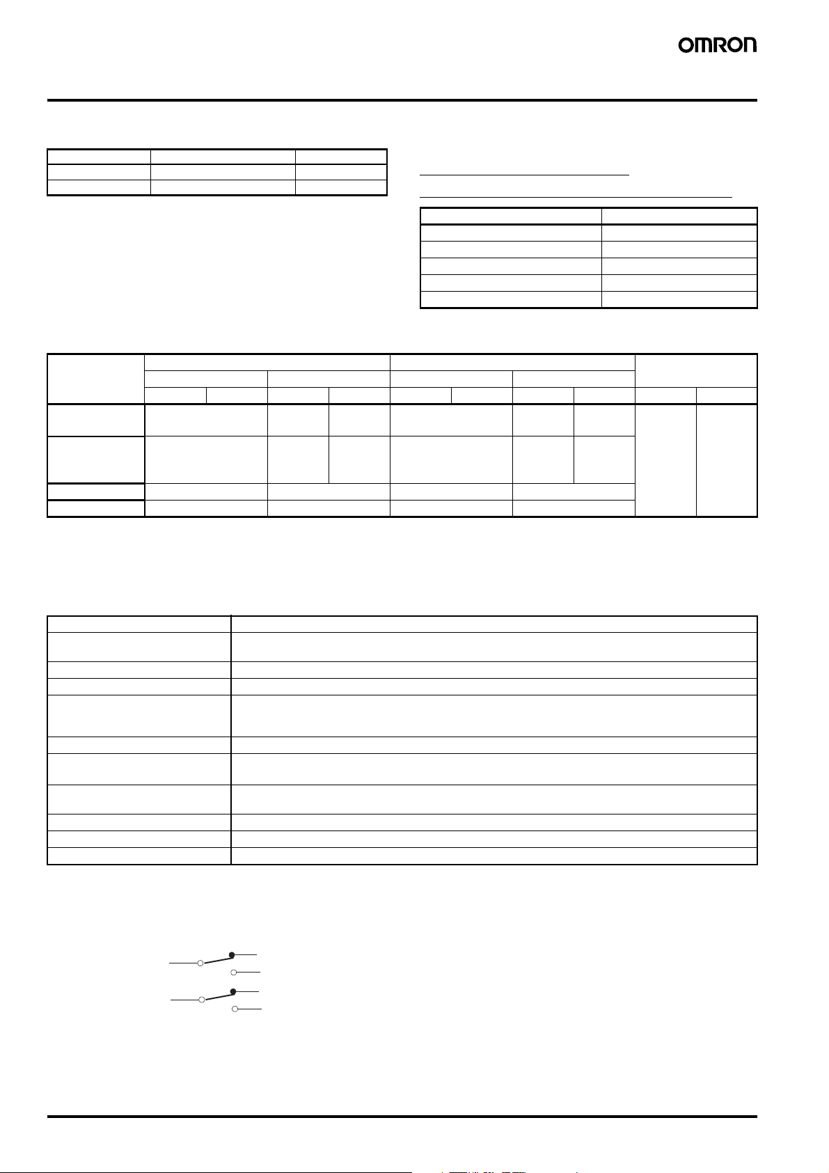
■ Contact Form (DPDT)
COM1
COM2
NC1
NO1
NC2
NO2
F-140 Special-purpose Basic Switch DZ
 Loading...