

Omron DEVICENET SAFETY - 04-2005, DeviceNet Safety, DST1-ID12SL-1, DST1-MD16SL-1, DST1-MRD08SL-1 Operation Manual
...
DST1-series
Safety I/O Terminals
OPERATION MANUAL
DeviceNet Safety
DST1-ID12SL-1 Safety Input Terminal
DST1-MD16SL-1 Safety I/O Terminal
with Semiconductor Outputs
DST1-MRD08SL-1 Safety I/O Terminal
with Relay Outputs
Cat.No. Z904-E2-01


DST1-series Safety I/O Terminals
Operation Manual
Produced April 2005

5
Notice
OMRON products are manufactured for use according to proper procedures by a qualified operator and only
for the purposes described in this manual.
The following conventions are used to indicate and classify precautions in this manual. Always heed the information provided with them. Failure to heed precautions can result in injury to people or damage to property.
OMRON Product References
All OMRON products are capitalized in this manual. The word "Unit" is also capitalized when it refers to an
OMRON product, regardless of whether or not it appears in the proper name of the product.
The abbreviation "PLC" means Programmable Controller. “PC” is used, however, in some Programming Device displays to mean Programmable Controller.
Visual Aids
The following headings appear in the left column of the manual to help you locate different types of information.
IMPORTANT: Indicates important information on what to do or not to do to prevent failure to operation,
malfunction, or undesirable effects on product performance.
Note: Indicates information of particular interest for efficient and convenient operation of the
product.
1,2,3… Indicates lists of one sort or another, such as procedures, checklists, etc.
Trademarks and Copyrights
DeviceNet and DeviceNet Safety are registered trademarks of the Open DeviceNet Vendors Association.
Other product names and company names in this manual are trademarks or registered trademarks of their
respective companies.
The copyright of the DeviceNet Safety DST1-series Safety I/O Terminals belongs to OMRON Corporation.
© OMRON, 2005
All rights reserved. No part of this publication may be reproduced, stored in a retrieval system, or transmitted,
in any form, or by any means, mechanical, electronic, photocopying, recording, or otherwise, without the prior
written permission of OMRON.
No patent liability is assumed with respect to the use of the information contained herein. Moreover, because
OMRON is constantly striving to improve its high-quality products, the information contained in this manual
is subject to change without notice. Every precaution has been taken in the preparation of this manual. Nevertheless, OMRON assumes no responsibility for errors or omissions. Neither is any liability assumed for
damages resulting from the use of the information contained in this publication.
! WARNING
Indicates an imminently hazardous situation which, if not avoided, is likely to result in
serious injury or may result in death. Additionally, there may be severe property damage.
! WARNING
Indicates a potentially hazardous situation which, if not avoided, will result in minor or
moderate injury, or may result in serious injury or death. Additionally, there may be severe property damage.
! CAUTION
Indicates a potentially hazardous situation which, if not avoided, may result in minor
or moderate injury or in property damage.
Indicates required actions.
Indicates prohibited actions.

6
7
About this Manual
This manual describes the installation and operation of a DST1-series Safety I/O Terminals (referred to as
the DST1 in this manual).
Please read this manual carefully and be sure you understand the information provided before attempting to
install or operate the DST1. Be sure to read the precautions provided in the following section.
The following manuals provide information on the DeviceNet and DeviceNet Safety.
Read and Understand this Manual
Please read and understand this manual before using the product. Please consult your OMRON representative if you have any questions or comments.
Warranty and Limitations of Liability
Manual Products Contents Cat. No.
DeviceNet Safety
DST1-series Safety I/O Terminals
Operation Manual (This manual)
DST1-series
Safety I/O Terminals
Information on DST1-series
Safety I/O Terminals
Z904
DeviceNet Safety
System Configuration Manual
WS02-CFSC1-E Information on using the Network
Configurator
Z905
DeviceNet Operation Manual Describes the network configuration and connection
modes of a DeviceNet network. Also provides details on
connection methods, specifications, and power supply
methods to the communications systems of connection
devices, such as cables and connectors.
W267
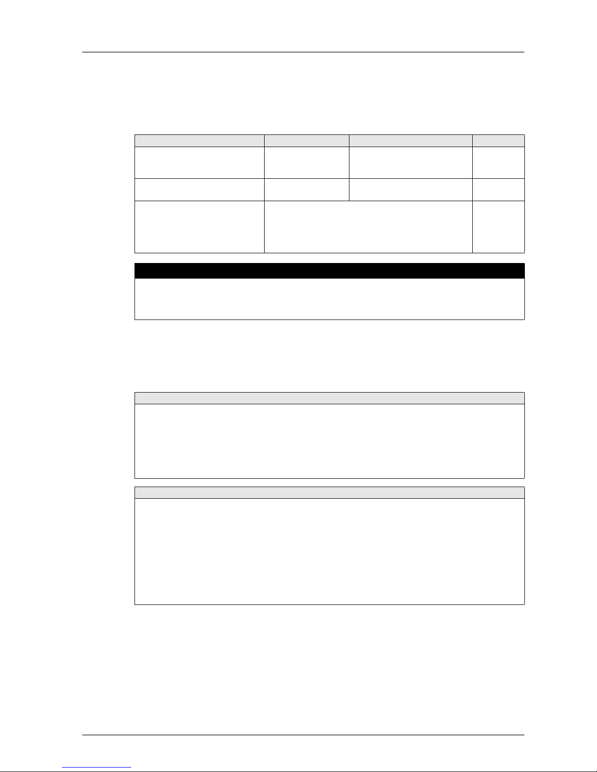
! WARNING
Failure to read and understand the information provided in this manual may result in personal injury or
death, damage to the product, or product failure. Please read each section in its entirety and be sure you
understand the information provided in the section and related sections before attempting any of the procedures or operations given.
WARRANTY
OMRON's exclusive warranty is that the products are free from defects in materials and workmanship for a
period of one year (or other period if specified) from date of sale by OMRON.
OMRON MAKES NO WARRANTY OR REPRESENTATION, EXPRESS OR IMPLIED, REGARDING NONINFRINGEMENT, MERCHANTABILITY, OR FITNESS FOR PARTICULAR PURPOSE OF THE
PRODUCTS. ANY BUYER OR USER ACKNOWLEDGES THAT THE BUYER OR USER ALONE HAS
DETERMINED THAT THE PRODUCTS WILL SUITABLY MEET THE REQUIREMENTS OF THEIR
INTENDED USE. OMRON DISCLAIMS ALL OTHER WARRANTIES, EXPRESS OR IMPLIED.
LIMITATIONS OF LIABILITY
OMRON SHALL NOT BE RESPONSIBLE FOR SPECIAL, INDIRECT, OR CONSEQUENTIAL DAMAGES,
LOSS OF PROFITS OR COMMERCIAL LOSS IN ANY WAY CONNECTED WITH THE PRODUCTS,
WHETHER SUCH CLAIM IS BASED ON CONTRACT, WARRANTY, NEGLIGENCE, OR STRICT
LIABILITY.
In no event shall the responsibility of OMRON for any act exceed the individual price of the product on which
liability is asserted.
IN NO EVENT SHALL OMRON BE RESPONSIBLE FOR WARRANTY, REPAIR, OR OTHER CLAIMS
REGARDING THE PRODUCTS UNLESS OMRON'S ANALYSIS CONFIRMS THAT THE PRODUCTS
WERE PROPERLY HANDLED, STORED, INSTALLED, AND MAINTAINED AND NOT SUBJECT TO
CONTAMINATION, ABUSE, MISUSE, OR INAPPROPRIATE MODIFICATION OR REPAIR.

8
Application Considerations
Disclaimers
SUITABILITY FOR USE
OMRON shall not be responsible for conformity with any standards, codes, or regulations that apply to the
combination of products in the customer's application or use of the products.
At the customer's request, OMRON will provide applicable third party certification documents identifying ratings and limitations of use that apply to the products. This information by itself is not sufficient for a complete
determination of the suitability of the products in combination with the end product, machine, system, or other application or use.
The following are some examples of applications for which particular attention must be given. This is not
intended to be an exhaustive list of all possible uses of the products, nor is it intended to imply that the uses
listed may be suitable for the products:
• Outdoor use, uses involving potential chemical contamination or electrical interference, or conditions
or uses not described in this manual.
• Nuclear energy control systems, combustion systems, railroad systems, aviation systems, medical
equipment, amusement machines, vehicles, safety equipment, and installations subject to separate
industry or government regulations.
• Systems, machines, and equipment that could present a risk to life or property.
Please know and observe all prohibitions of use applicable to the products.
NEVER USE THE PRODUCTS FOR AN APPLICATION INVOLVING SERIOUS RISK TO LIFE OR PROP-
ERTY WITHOUT ENSURING THAT THE SYSTEM AS A WHOLE HAS BEEN DESIGNED TO ADDRESS
THE RISKS, AND THAT THE OMRON PRODUCTS ARE PROPERLY RATED AND INSTALLED FOR THE
INTENDED USE WITHIN THE OVERALL EQUIPMENT OR SYSTEM.
PROGRAMMABLE PRODUCTS
OMRON shall not be responsible for the user's programming of a programmable product, or any consequence thereof.
CHANGE IN SPECIFICATIONS
Product specifications and accessories may be changed at any time based on improvements and other reasons.
It is our practice to change model numbers when published ratings or features are changed, or when significant construction changes are made. However, some specifications of the products may be changed without any notice. When in doubt, special model numbers may be assigned to fix or establish key specifications
for your application on your request. Please consult with your OMRON representative at any time to confirm
actual specifications of purchased products.
DIMENSIONS AND WEIGHTS
Dimensions and weights are nominal and are not to be used for manufacturing purposes, even when tolerances are shown.
PERFORMANCE DATA
Performance data given in this manual is provided as a guide for the user in determining suitability and does
not constitute a warranty. It may represent the result of OMRON's test conditions, and the users must correlate it to actual application requirements. Actual performance is subject to the OMRON Warranty and Limitations of Liability.
ERRORS AND OMISSIONS
The information in this manual has been carefully checked and is believed to be accurate; however, no responsibility is assumed for clerical, typographical, or proofreading errors, or omissions.

9
Precautions
1 Intended Audience
This manual is intended for the following personnel, who must have knowledge of electrical systems (an electrical engineer or the equivalent).
• Personnel in charge of introducing FA and safety systems into production facilities
• Personnel in charge of designing FA and safety systems
• Personnel in charge of managing FA facilities
• Personnel who have the qualifications, authority, and obligation to provide safety during each of the following product phases: mechanical design, installation, operation, maintenance, and disposal
2 General Precautions
The user must operate the product according to the performance specifications described in the operation
manuals.
Before using the product under conditions which are not described in the manual or applying the product to
nuclear control systems, railroad systems, aviation systems, vehicles, combustion systems, medical equipment, amusement machines, safety equipment, and other systems, machines, and equipment that may have
a serious influence on lives and property if used improperly, consult your OMRON representative.
Make sure that the ratings and performance characteristics of the product are sufficient for the systems, machines, and equipment, and be sure to provide the systems, machines, and equipment with double safety
mechanisms.
This manual provides information for programming and operating the Unit. Be sure to read this manual before
attempting to use the Unit and keep this manual close at hand for reference during operation.
! Warning
It is extremely important that a PLC and all PLC Units be used for the specified purpose and under the specified conditions, especially in applications thatcan directly or indirectly affect human life. You must consult
with your OMRON representative before applying a PLC System to the above-mentioned applications.

10
! WARNING
This is the Operation Manual for the DST1-series Safety I/O Terminals. Heed the following items during system construction to ensure that safety-related components are configured in a manner that allows the system functions to sufficiently operate.
Risk Assessment
The proper use of the safety device described in this Operation Manual as it relates to installation conditions
and mechanical performance and functions is a prerequisite for its use. When selecting or using this safety
device, risk assessment must be conducted with the aim of identifying potential danger factors in equipment
or facilities in which the safety device is to be applied, during the development stage of the equipment or
facilities. Suitable safety devices must be selected under the guidance of a sufficient risk assessment system. An insufficient risk assessment system may lead to the selection of unsuitable safety devices.
• Typical related international standards: ISO 14121, Safety of Machinery -- Principles of Risk Assessment
Safety Measures
When using this safety device to build systems containing safety-related components for equipment or facilities, the system must be designed with the full understanding of and conformance to international standards, such as those listed below, and/or standards in related industries.
• Typical related international standards: ISO/DIS 12100, Safety of Machinery -- Basic Concepts and
General Principles for Design IEC 61508, Safety Standard for Safety Instrumented Systems (Functional Safety of Electrical/Electronic/Programmable Electronic Safety-related Systems)
Role of Safety Device
This safety device is provided with safety functions and mechanisms as stipulated in relevant standards, but
suitable designs must be used to allow these functions and mechanisms to operate properly inside system
constructions containing safety-related components. Build systems that enable these functions and mechanisms to perform properly, based on a full understanding of their operation.
• Typical related international standards: ISO 14119, Safety of Machinery -- Interlocking Devices Associated with Guards -- Principles of Design and Selection
Installation of Safety Device
The construction and installation of systems with safety-related components for equipment or facilities must
be performed by technicians who have received suitable training.
• Typical related international standards: ISO/DIS 12100, Safety of Machinery -- Basic Concepts and
General Principles for Design IEC 61508, Safety Standard for Safety Instrumented Systems (Functional Safety of Electrical/Electronic/Programmable Electronic Safety-related Systems)
Complying with Laws and Regulations
This safety device conforms to the relevant regulations and standards, but make sure that it is used in compliance with local regulations and standards for the equipment or facilities in which it is applied.
• Typical related international standards: IEC 60204, Safety of Machinery -- Electrical Equipment of
Machines
Observing Precautions for Use
When putting the selected safety device to actual use, heed the specifications and precautions in this Operation Manual and those in the Instruction Manual that comes with the product. Using the product in a manner that deviates from these specifications and precautions will lead to unexpected failures in equipment or
devices, and to damages that result from such failures, due to insufficient operating functions in safety-related components.
Moving or Transferring Devices or Equipment
When moving or transferring devices or equipment, be sure to include this Operation Manual to ensure that
the person to whom the device or equipment is being moved or transferred will be able to operate it properly.
• Typical related international standards: ISO/DIS 12100 ISO, Safety of Machinery -- Basic Concepts
and General Principles for Design IEC 61508, Safety Standard for Safety Instrumented Systems
(Functional Safety of Electrical/Electronic/Programmable Electronic Safety-related Systems)
11
3 Safety Precautions
! WARNING
Serious injury may possibly occur due to loss of required safety functions. Do not use test
outputs of the DST1 as any safety outputs.
Serious injury may possibly occur due to loss of required safety functions. Do not use DeviceNet standard I/O data or Explicit message data as any safety data.
Serious injury may possibly occur due to loss of required safety functions. Do not use LEDs
on the DST1 for safety operations.
Serious injury may possibly occur due to breakdown of safety outputs. Do not connect loads
beyond the rated value to the safety outputs.
Serious injury may possibly occur due to loss of required safety functions. Wire the DST1
properly so that DC24V line do NOT touch the safety outputs accidentally or unintentionally.
Serious injury may possibly occur due to loss of required safety functions. Ground the 0V line
of the power supply for external output devices so that the devices do Not turn ON when the
safety output line is grounded.
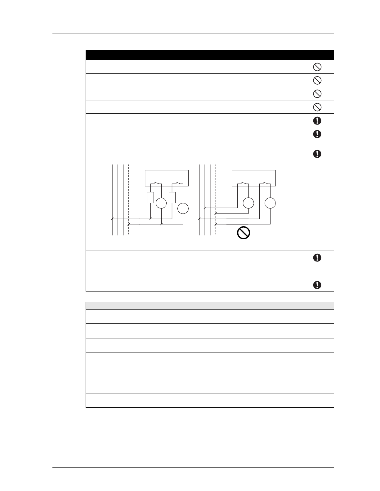
For Model DST1-MRD08SL-1, Apply only one AC line phase to the relays output
For Model DST1-MRD08SL-1, Insert a fuse rated at 3.15A or less for each output terminal to
protect safety output contacts from welding.
Confirm the fuse selection with the fuse manufacturer to ensure the dependability of the characteristics of the connected load.
Serious injury may possibly occur due to loss of safety functions. Use appropriate devices according to the requirements given in the following table.
Controlling devices Requirements
Emergency stop switches Use approved switches with a direct opening mechanism complying with IEC/
EN 60947-5-1.
Door interlocking switches
Limit switches
Use approved switches with a direct opening mechanism complying with IEC/
EN 60947-5-1 and capable of switching micro-loads of 5 mA at 24 V DC.
Safety sensor Use approved sensors complying with the relevant product standards, regula-
tions, and rules in the country where it is used.
Relay with forcibly guided
contacts
Use approved devices with forcibly guided contacts compliant with EN 50205.
For feedback, use devices with contacts capable of switching micro-loads of
4 mA at 24 VDC.
Contactor Use approved relays with forcibly guided contacts complying with EN 50205.
For feedback purpose, use devices with contacts capable of switching micro-
loads of 5 mA at 24 V DC.
Other devices Evaluate whether devices used are appropriate to satisfy the requirements of
safety category.
L1 L2 L3 N
DST1-
MRD08SL-1
L1 L2 L3 N
DST1-
MRD08SL-1
Fuse
Fuse
Load
Load LoadLoad
Correct Incorrect

12
4 Precautions for Safe Use
Handle with care
Do not drop the DST1 to the ground or excessive vibration or mechanical shocks. The DST1 may be damaged and may not function properly.
Installation and storage environment
Do not use or store the DST1 in any of the following locations.
• Locations subject to direct sunlight.
• Locations subject to temperatures or humidity outside the range specified in the specifications.
• Locations subject to condensation as the result of severe changes in temperature.
• Locations subject to dust (especially iron dust) or salts
• Locations subject to dust (especially iron dust) or salts.
• Locations subject to water, oil, or chemicals.
• Locations subject to shock or vibration.
Take appropriate and sufficient countermeasures when installing systems in the following locations. Inappro-
priate and insufficient measures may result in malfunction.
• Locations subject to static electricity or other forms of noise.
• Locations subject to strong electromagnetic fields
• Locations subject to possible exposure to radioactivity.
• Locations close to power supplies.
Installation/ Mounting
• Use the DST1 within an enclosure with IP54 protection or higher of IEC/EN 60529.
• Use DIN rail (TH35-7.5 according to IEC60715) for placing the DST1 into the control board.
• Mount the DST1 to DIN rails with attachments (TYPE PFP-M, not incorporated to this product), not to
drop out of rails by vibration etc.
• Spacing should be available around the DST1 at least 50mm from its top and bottom surfaces for ventilation and wiring.
Installation/ Wiring
• Use the following to wire external I/O devices to the DST1.
• Disconnect the DST1 from power supply when wiring. Devices connected to DST1 may operate unexpectedly.
• Apply properly specified voltages to the DST1 inputs. Applying inappropriate DC voltage and any AC
voltages cause the DST1 to fail.
• Be sure to separate the communication cable and the I/O cable from the high-voltage/ current lines.
• Be cautious not to have your fingers caught when attaching connectors to the plugs on the DST1.
• Mount screw of DeviceNet Connector and I/O Connector correctly(0.25-0.3 Nm).
• Incorrect wiring may lead to loss of safety function. Wire conductors correctly and verify the operation of
the DST1 before commissioning the system in which DST1 is incorporated.
• After wiring is completed, be sure to remove label for wire clipping prevention on the DST1 to enable
heat to escape for proper cooling
Power Supply Selection
Use DC power supply satisfying requirements below.
• Secondary circuits of DC power supply is isolated from its primary circuit by double insulations or reinforced insulations
• DC power supply satisfies the requirement for class 2 circuits or limited voltage/current circuit stated in
UL 508.
• 20ms or over of the output hold time.
Solid wire 0.2 ~ 2.5 mm2 AWG 24 ~ 12
Standard (Flexible) wire 0.34 ~ 1.5 mm2 AWG 22 ~ 16
Standard wire should be processed with insulation-covered bar terminal
(DIN46228-4 standard compatible type) at its ends before using for connection.

13
Periodical Inspection and Maintenance
• Disconnect the DST1 from power supply when replacing. Devices connected to the DST1 may operate
unexpectedly.
• Do not dismantle, repair, or modify the DST1. It may lead to loss of its safety functions.
Disposal
• Be cautious not to have you injured when dismantling the DST1.
5 Additional Precautions According to UL 1604
DST1-ID12SL-1 and DST1-MD16SL-1 are suitable for use in Class I, Div. 2, Group A, B, C, D or Non-Hazardous Location Only.
WARNING - Explosion Hazard - Substitution of Components May Impair Suitability For Class I, Div. 2.
WARNING - Explosion Hazard - Do not Disconnect Equipment Unless Power Has Been Switched Off Or The
Area Is Known To Be Non-Hazardous.
6 Regulations and Standards
The DST1-series Safety I/O Terminals has been certified as follows by TUV Rheinland:
1. European Standards
• EN 954-1/12.96
• EN 60204-1/12.97
• EN 61000-6-2/10.01
• EN 61000-6-4/10.01
• EN 418/1992
2. International Standards
• IEC 61508 part1-7/12.98-05.00
• IEC 61131-2/02.03
3. U.S.A. Standards
• NFPA 79-2002
• ANSI RIA15.06-1999
• ANSI B11.19-2003
The DST1 has been certified as follows by Underwriter's Laboratory:
Listings for U.S. and Canadian Safety Standards
• UL1998
•NFPA 79
• UL 508
• CSA 22.2 No14
• UL 1604 (For Model DST1-ID12SL-1 and Model DST1-MD16SL-1)

14

Table of contents 15
Table of contents
Notice . . . . . . . . . . . . . . . . . . . . . . . . . . . . . . . . . . . . . . . . . . . . . . 5
OMRON Product References . . . . . . . . . . . . . . . . . . . . . . . . . . . . . . . . . . 5
Visual Aids . . . . . . . . . . . . . . . . . . . . . . . . . . . . . . . . . . . . . . . . . . . . 5
About this Manual . . . . . . . . . . . . . . . . . . . . . . . . . . . . . . . . . . . . . . . . 7
Precautions . . . . . . . . . . . . . . . . . . . . . . . . . . . . . . . . . . . . . . . . . . . 9
1 Intended Audience . . . . . . . . . . . . . . . . . . . . . . . . . . . . . . . 9
2 General Precautions. . . . . . . . . . . . . . . . . . . . . . . . . . . . . . . 9
3 Safety Precautions . . . . . . . . . . . . . . . . . . . . . . . . . . . . . . . 11
4 Precautions for Safe Use . . . . . . . . . . . . . . . . . . . . . . . . . . . . 12
5 Additional Precautions According to UL 1604 . . . . . . . . . . . . . . . . . . 13
6 Regulations and Standards . . . . . . . . . . . . . . . . . . . . . . . . . . . 13
Section 1: Overview 19
1-1 Overview . . . . . . . . . . . . . . . . . . . . . . . . . . . . . . . . . . . . . . . . . . . . 20
1-1-1 About the DST1-series Safety I/O Terminals . . . . . . . . . . . . . . . . . . . 20
1-1-2 DST1-series Safety I/O Terminals Features . . . . . . . . . . . . . . . . . . . . 20
1-2 Standard Models . . . . . . . . . . . . . . . . . . . . . . . . . . . . . . . . . . . . . . . . 22
1-3 Functions . . . . . . . . . . . . . . . . . . . . . . . . . . . . . . . . . . . . . . . . . . . . 23
1-3-1 DST1-series Safety I/O Terminals . . . . . . . . . . . . . . . . . . . . . . . . . 23
1-3-2 Safety Inputs . . . . . . . . . . . . . . . . . . . . . . . . . . . . . . . . . . . . 25
1-3-3 Test Outputs . . . . . . . . . . . . . . . . . . . . . . . . . . . . . . . . . . . . 26
1-3-4 Safety Outputs . . . . . . . . . . . . . . . . . . . . . . . . . . . . . . . . . . . 26
1-4 Description of Safety Functions . . . . . . . . . . . . . . . . . . . . . . . . . . . . . . . 27
1-4-1 DST1-series Safety I/O Terminals . . . . . . . . . . . . . . . . . . . . . . . . . 27
1-4-2 Safety Inputs . . . . . . . . . . . . . . . . . . . . . . . . . . . . . . . . . . . . 28
1-4-3 Safety Outputs . . . . . . . . . . . . . . . . . . . . . . . . . . . . . . . . . . . 32
1-4-4 Input Reaction Time . . . . . . . . . . . . . . . . . . . . . . . . . . . . . . . . 33
1-4-5 Output Reaction Time . . . . . . . . . . . . . . . . . . . . . . . . . . . . . . . 33
1-4-6 I/O Status Data. . . . . . . . . . . . . . . . . . . . . . . . . . . . . . . . . . . 34
Section 2: General Procedure 35
2-1 General Procedure . . . . . . . . . . . . . . . . . . . . . . . . . . . . . . . . . . . . . . . 36
2-2 Installation . . . . . . . . . . . . . . . . . . . . . . . . . . . . . . . . . . . . . . . . . . . 37
2-3 Connecting I/O Power and I/O Cable . . . . . . . . . . . . . . . . . . . . . . . . . . . . . 38
2-4 Connecting the Communications Connector . . . . . . . . . . . . . . . . . . . . . . . . 39
2-5 Node Address . . . . . . . . . . . . . . . . . . . . . . . . . . . . . . . . . . . . . . . . . 39
2-6 Configuration . . . . . . . . . . . . . . . . . . . . . . . . . . . . . . . . . . . . . . . . . . 39
Section 3: Configuration 41
3-1 Set I/O Parameters . . . . . . . . . . . . . . . . . . . . . . . . . . . . . . . . . . . . . . . 42
3-1-1 General Parameters . . . . . . . . . . . . . . . . . . . . . . . . . . . . . . . . 42
3-1-2 Safety Input Parameters . . . . . . . . . . . . . . . . . . . . . . . . . . . . . . 43
3-1-3 Test Output Parameters . . . . . . . . . . . . . . . . . . . . . . . . . . . . . . 44
3-1-4 Safety Output Parameters . . . . . . . . . . . . . . . . . . . . . . . . . . . . . 44
3-1-5 Operation Time Parameters . . . . . . . . . . . . . . . . . . . . . . . . . . . . 45

16 Table of contents
3-2 Remote I/O Allocations . . . . . . . . . . . . . . . . . . . . . . . . . . . . . . . . . . . . 46
3-2-1 I/O Allocations . . . . . . . . . . . . . . . . . . . . . . . . . . . . . . . . . . 46
3-2-2 I/O Data . . . . . . . . . . . . . . . . . . . . . . . . . . . . . . . . . . . . . . 46
3-2-3 I/O Data Supported by Each Model. . . . . . . . . . . . . . . . . . . . . . . . 47
3-2-4 I/O Assembly Data . . . . . . . . . . . . . . . . . . . . . . . . . . . . . . . . 49
Section 4: Specifications 55
4-1 Specifications . . . . . . . . . . . . . . . . . . . . . . . . . . . . . . . . . . . . . . . . . 56
4-1-1 Common Specifications. . . . . . . . . . . . . . . . . . . . . . . . . . . . . . 56
4-1-2 Current Consumption and Weights . . . . . . . . . . . . . . . . . . . . . . . . 56
4-1-3 DeviceNet Communications Specifications. . . . . . . . . . . . . . . . . . . . 56
4-2 Indicators . . . . . . . . . . . . . . . . . . . . . . . . . . . . . . . . . . . . . . . . . . . 57
4-2-1 MS/NS Indicators . . . . . . . . . . . . . . . . . . . . . . . . . . . . . . . . . 57
4-2-2 Configuration Lock Indicator . . . . . . . . . . . . . . . . . . . . . . . . . . . 57
4-2-3 IN PWR/OUT PWR Indicators . . . . . . . . . . . . . . . . . . . . . . . . . . 57
4-2-4 I/O Indicators . . . . . . . . . . . . . . . . . . . . . . . . . . . . . . . . . . . 58
Section 5: DST1-series 59
5-1 Safety Input Terminal . . . . . . . . . . . . . . . . . . . . . . . . . . . . . . . . . . . . . 60
5-1-1 Safety Input Specifications . . . . . . . . . . . . . . . . . . . . . . . . . . . . 60
5-1-2 Test Output Specifications . . . . . . . . . . . . . . . . . . . . . . . . . . . . 60
5-1-3 Nomenclature . . . . . . . . . . . . . . . . . . . . . . . . . . . . . . . . . . . 60
5-1-4 Internal Circuits and Terminal Arrangement . . . . . . . . . . . . . . . . . . . 61
5-1-5 Dimensions . . . . . . . . . . . . . . . . . . . . . . . . . . . . . . . . . . . . 62
5-2 Safety I/O Terminal with Semiconductor Outputs . . . . . . . . . . . . . . . . . . . . . 63
5-2-1 Safety Input Specifications . . . . . . . . . . . . . . . . . . . . . . . . . . . . 63
5-2-2 Test Output Specifications . . . . . . . . . . . . . . . . . . . . . . . . . . . . 63
5-2-3 Safety Output Specifications for Semiconductor Outputs . . . . . . . . . . . . 63
5-2-4 Nomenclature . . . . . . . . . . . . . . . . . . . . . . . . . . . . . . . . . . . 63
5-2-5 Internal Circuits and Terminal Arrangement . . . . . . . . . . . . . . . . . . . 64
5-2-6 Dimensions . . . . . . . . . . . . . . . . . . . . . . . . . . . . . . . . . . . . 65
5-3 Safety I/O Terminal with Relay Outputs . . . . . . . . . . . . . . . . . . . . . . . . . . . 66
5-3-1 Safety Input Specifications . . . . . . . . . . . . . . . . . . . . . . . . . . . . 66
5-3-2 Test Output Specifications . . . . . . . . . . . . . . . . . . . . . . . . . . . . 66
5-3-3 Safety Output Specifications for Relay Outputs . . . . . . . . . . . . . . . . . 66
5-3-4 Nomenclature . . . . . . . . . . . . . . . . . . . . . . . . . . . . . . . . . . . 66
5-3-5 Internal Circuits and Terminal Arrangement . . . . . . . . . . . . . . . . . . . 67
5-3-6 Dimensions . . . . . . . . . . . . . . . . . . . . . . . . . . . . . . . . . . . . 69
Section 6: Troubleshooting and Maintenance 71
6-1 Indicators and Error Processing . . . . . . . . . . . . . . . . . . . . . . . . . . . . . . . 72
6-2 Troubleshooting . . . . . . . . . . . . . . . . . . . . . . . . . . . . . . . . . . . . . . . 73
6-2-1 Safety Input Errors . . . . . . . . . . . . . . . . . . . . . . . . . . . . . . . . 73
6-2-2 Test Output Errors . . . . . . . . . . . . . . . . . . . . . . . . . . . . . . . . 74
6-2-3 Safety Output Errors . . . . . . . . . . . . . . . . . . . . . . . . . . . . . . . 75
6-3 Error History. . . . . . . . . . . . . . . . . . . . . . . . . . . . . . . . . . . . . . . . . . 76
6-4 Maintenance . . . . . . . . . . . . . . . . . . . . . . . . . . . . . . . . . . . . . . . . . . 77
6-4-1 Cleaning . . . . . . . . . . . . . . . . . . . . . . . . . . . . . . . . . . . . . 77
6-4-2 Inspection . . . . . . . . . . . . . . . . . . . . . . . . . . . . . . . . . . . . . 77
6-4-3 Replacing the DST1 . . . . . . . . . . . . . . . . . . . . . . . . . . . . . . . 78

Table of contents 17
Section 7: Wiring Examples 79
7-1 Wiring and Configuration . . . . . . . . . . . . . . . . . . . . . . . . . . . . . . . . . . . 80
7-2 Examples of Wiring for Each Application . . . . . . . . . . . . . . . . . . . . . . . . . . 81
7-2-1 Emergency Stop Switch Dual Channel Inputs with Manual Reset . . . . . . . . . 81
7-2-2 Two-Hand Input . . . . . . . . . . . . . . . . . . . . . . . . . . . . . . . . . . 81
7-2-3 User Mode Switch Input . . . . . . . . . . . . . . . . . . . . . . . . . . . . . . 82
7-2-4 Muting Lamp Output . . . . . . . . . . . . . . . . . . . . . . . . . . . . . . . . 83
7-2-5 Limit Switch Dual Channel Inputs and a Manual Reset . . . . . . . . . . . . . . 83
7-2-6 Safety Light Curtain Input . . . . . . . . . . . . . . . . . . . . . . . . . . . . . 84
7-2-7 Semiconductor Outputs for Dual Channel Mode. . . . . . . . . . . . . . . . . . 85
7-2-8 Relay Outputs with Dual Channel Mode and EDM Input . . . . . . . . . . . . . 86
Appendices 87
A DeviceNet Explicit Messages . . . . . . . . . . . . . . . . . . . . . . . . . . . . . . . . . 89
A-1 Basic Format of Explicit Messages . . . . . . . . . . . . . . . . . . . . . . . . 89
A-2 Explicit Messages . . . . . . . . . . . . . . . . . . . . . . . . . . . . . . . . . 90
A-3 Using Explicit Messages . . . . . . . . . . . . . . . . . . . . . . . . . . . . . . 97
B Calculated Values of PFD and PFH . . . . . . . . . . . . . . . . . . . . . . . . . . . . . . 99
B-1 Calculated PFD Values . . . . . . . . . . . . . . . . . . . . . . . . . . . . . . 99
B-2 Calculated PFH Values . . . . . . . . . . . . . . . . . . . . . . . . . . . . . . 99
Glossary 101
Index 103
Revision History 105

18 Table of contents

19
Section 1: Overview
1-1 Overview . . . . . . . . . . . . . . . . . . . . . . . . . . . . . . . . . . . . . . . . . . . . 20
1-1-1 About the DST1-series Safety I/O Terminals . . . . . . . . . . . . . . . . . . . 20
1-1-2 DST1-series Safety I/O Terminals Features . . . . . . . . . . . . . . . . . . . . 20
1-2 Standard Models . . . . . . . . . . . . . . . . . . . . . . . . . . . . . . . . . . . . . . . . 22
1-3 Functions . . . . . . . . . . . . . . . . . . . . . . . . . . . . . . . . . . . . . . . . . . . . 23
1-3-1 DST1-series Safety I/O Terminals . . . . . . . . . . . . . . . . . . . . . . . . . 23
1-3-2 Safety Inputs . . . . . . . . . . . . . . . . . . . . . . . . . . . . . . . . . . . . 25
1-3-3 Test Outputs . . . . . . . . . . . . . . . . . . . . . . . . . . . . . . . . . . . . 26
1-3-4 Safety Outputs . . . . . . . . . . . . . . . . . . . . . . . . . . . . . . . . . . . 26
1-4 Description of Safety Functions . . . . . . . . . . . . . . . . . . . . . . . . . . . . . . . 27
1-4-1 DST1-series Safety I/O Terminals . . . . . . . . . . . . . . . . . . . . . . . . . 27
1-4-2 Safety Inputs . . . . . . . . . . . . . . . . . . . . . . . . . . . . . . . . . . . . 28
1-4-3 Safety Outputs . . . . . . . . . . . . . . . . . . . . . . . . . . . . . . . . . . . 32
1-4-4 Input Reaction Time . . . . . . . . . . . . . . . . . . . . . . . . . . . . . . . . 33
1-4-5 Output Reaction Time . . . . . . . . . . . . . . . . . . . . . . . . . . . . . . . 33
1-4-6 I/O Status Data. . . . . . . . . . . . . . . . . . . . . . . . . . . . . . . . . . . 34
20 Section 1: Overview
1-1 Overview
1-1-1 About the DST1-series Safety I/O Terminals
The DST1-series Safety I/O Terminals support the DeviceNet Safety protocol and provide various functions
for the Safety System. The DST1-series Safety I/O Terminals allow the user to construct a safety control/
network system that meets the requirements for Safety Integrity Level (SIL) 3 according to IEC 61508 (Functional Safety of Electrical/Electronic/ Programmable Electronic Safety-related Systems) and the requirements for Safety Category 4 according to EN 954-1.
The DST1-series Safety I/O Terminal's safety I/O data is transmitted through safety I/O communications conforming to the DeviceNet Safety Protocol, and the data processing is performed in conducted in the Safety
Network Controller (NE1A-SCPU01). Also, the status of the safety I/O data can be monitored in a standard
PLC in an existing DeviceNet network using standard I/O communications or explicit message communications.Dual Channel Complementary
1-1-2 DST1-series Safety I/O Terminals Features
Safety Inputs
• Semiconductor output devices such light curtains can be connected as well as contact output devices
such as emergency stop switches.
• Faults in external wiring can be detected.
• Input delays (ON delays and OFF delays) can be set.
• Pairs of related local inputs can be set to Dual Channel Mode in order to be compliant with the Category
4 standards.
When Dual Channel Mode is set, the input data patterns and the time discrepancy between input signals can be evaluated.
Test Outp uts
• 4 independent test outputs are available to use.
• A disconnected external indicator lamp can be detected. (Can be set for the T3 Terminal only.)
• Test outputs can be used as power supply terminals to devices such as sensors.
• Test outputs can be used as the standard output terminals for monitor outputs.
Safety Outputs
Semiconductor Outputs
• Pairs of related local outputs can be set to Dual Channel Mode in order to be compliant with the Category 4 standards.
• When Dual Channel Mode is set, the output data patterns can be evaluated.
• The rated output current is 0.5 A max. per output.
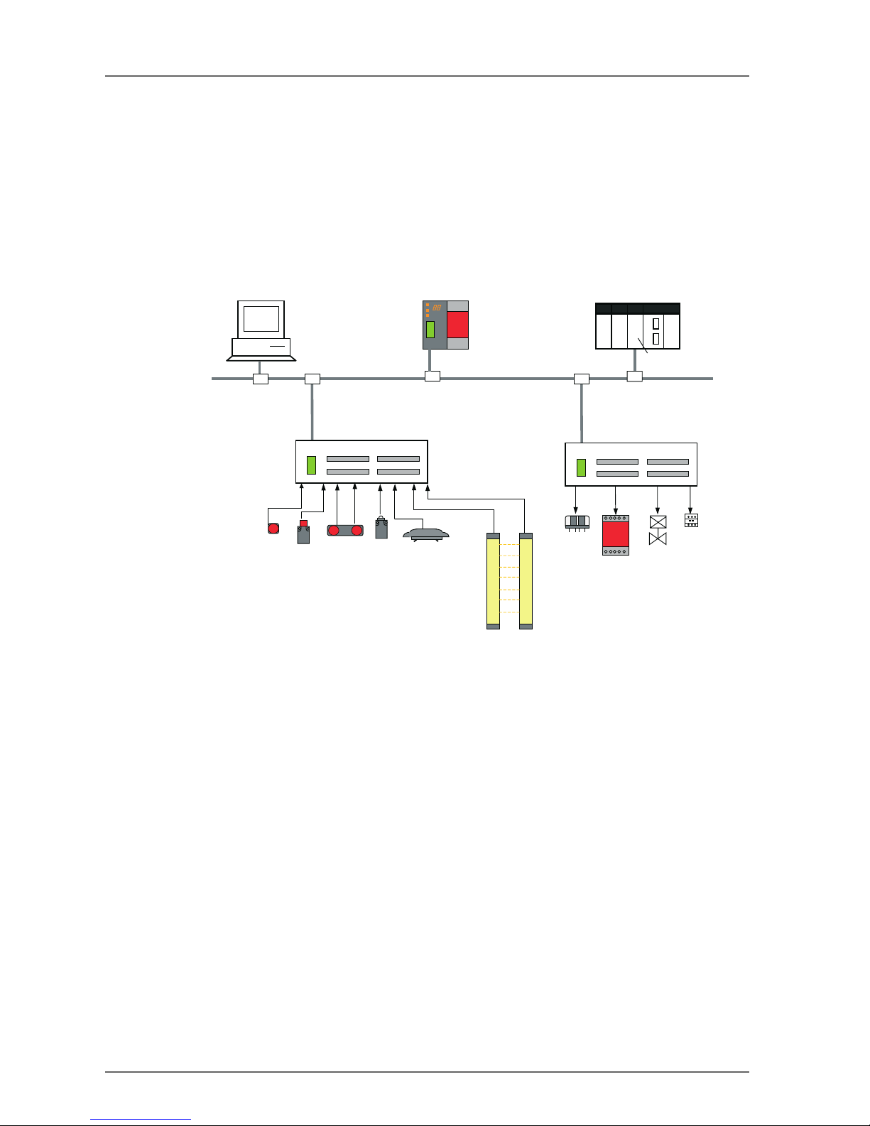
Network Configurator
DeviceNet Network
Safety Door Switch
Two-hand Switc h
Safety Limit Switch
Safety Light Curtain
Safety Relay
Enable Switc h
Safety Relay Unit
Valve
Safety Network Controller
PLC
DeviceNet Master
Contactor
DST1-series
Safety I/O Terminal
DST1-series
Safety I/O Terminal
Emergenc y Stop
Button

1-1 Overview 21
Relay Outputs
• Pairs of related output terminals can be set to Dual Channel Mode in order to be compliant with the Category 4 standards.
• When Dual Channel Mode is set, the output data patterns can be evaluated.
• The rated output current is 2 A max. per output.
• The safety relays can be replaced.
DeviceNet Safety Communications
As a Safety Slave, the DST1-series Safety I/O Terminals can perform safety I/O communications with up to
four connections.
DeviceNet Standard Communications
As a Standard Slave, the DST1-series Safety I/O Terminals can perform standard I/O communications with
one Standard Master with up to two connections.
System Startup and Error Recovery Support
• Error information can be checked by using the error log function or the indicators on the front of the
DST1-series Safety I/O Terminals.
• The DST1-series Safety I/O Terminal's safety I/O data and internal status information can be monitored
from a Standard PLC by allocating the information in the standard Master. In the same way, the information can be monitored from a safety PLC by allocating the information in the Safety Master.
Access Control with a Password
The DST1-series Safety I/O Terminals configuration data is protected by a password.
I/O Connector Connection/Disconnection
• The I/O Connector can be connected and disconnected.
• The I/O Connector is structured to prevent incorrect connection.
Cage Clamp Wiring
Cables can be wired without terminal screws.
Maintenance Functions
The DST1-series Safety I/O Terminals are equipped with Maintenance Functions such as a contact operation
counter, cumulative ON time monitor, and operating time monitor.
22 Section 1: Overview
1-2 Standard Models
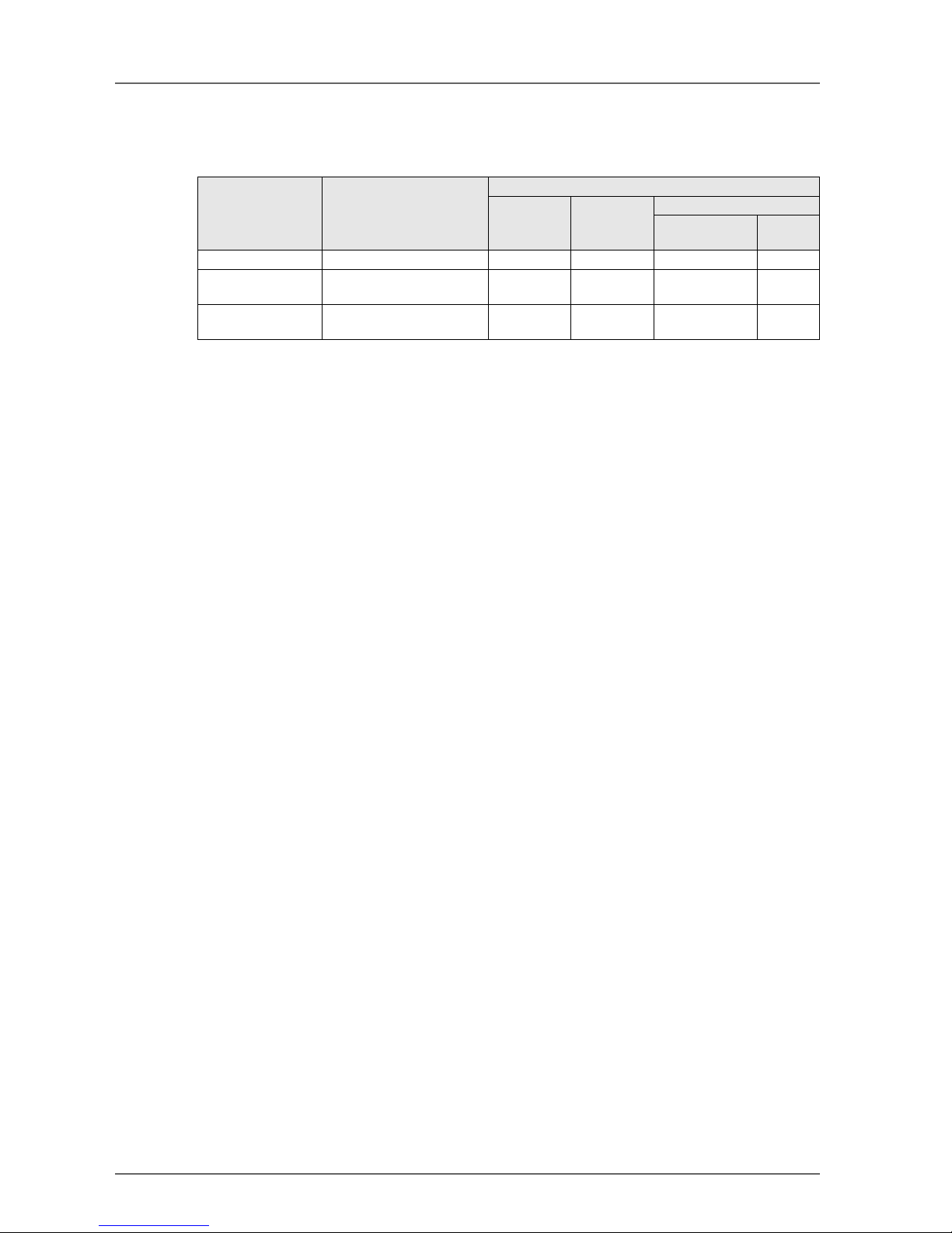
The following table shows the three models of DST1-series Safety I/O Terminals that are available: the Safety Input Terminal, Safety I/O Terminal (Semiconductor Output), and Safety Input/Output Terminal (Relay Output).
Model Name I/O capacity
Safety
inputs
Test
outputs
Safety outputs
Semiconductor
outputs
Relay
outputs
DST1-ID12SL-1 Safety Input Terminal 12 inputs 4 outputs
1
1
Each test output can be set to function as a test output or a standard output. Test outputs are used in
combination with a safety input. Broken wires in an external indicator can be detected for terminal T3
only.
--
DST1-MD16SL-1 Safety I/O Terminal with
Semiconductor outputs
8 inputs 4 outputs
1
8 outputs -
DST1-MRD08SL-1 Safety I/O Terminal with
Relay Outputs
4 inputs 4 outputs
1
- 4 outputs
1-3 Functions 23
1-3 Functions
1-3-1 DST1-series Safety I/O Terminals
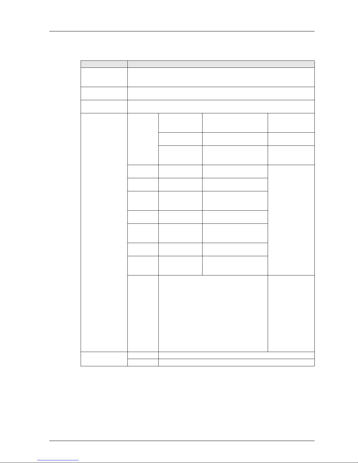
IMPORTANT: Communications with up to 15 Safety Controllers for each connection can be performed us-
ing multi-cast connection. If four connections are used, however, only a maximum of 30 Safety Controllers total can communicate with the DST1-series Safety I/O Terminals.
Item Description
Self-diagnosis functions
Self-diagnosis is performed when power is turned ON and periodically during operation. When an error occurs, it is treated as a fatal error, the MS indicator will light in
red, and all safety outputs and output data to the network will turn OFF.
Access Control by
Password
After configuration data has been downloaded and verified, configuration data within
the DST1-series Safety I/O Terminals can be protected by a password.
Automatic baud rate
detection
The DST1-series Safety I/O Terminals is automatically set to the baud rate of the network.
Contents of remote
I/O communications
I/O data for
control
Safety Inputs The ON/OFF status of each
safety input terminal
DST1 →
DeviceNet Master
Safety Master
Safety Outputs The ON/OFF status of each
safety output terminal
Safety Master →
DST1
Standard Outputs The ON/OFF status of each
test output terminal (T0 to
T3)
DeviceNet Master
or Safety Master →
DST1
Output
monitors
Safety Output
Monitors
The actual ON/OFF status of
each safety output
DST1 →
DeviceNet Master
Safety Master
Status data Individual Safety
Input Status
Normal flag for each safety
input
Combined Safety
Input Status
Common normal flag that is
ON when the all safety inputs
are normal
Individual Safety
Output Status
Normal flag for each safety
output
Combined Safety
Output Status
Common normal flag that is
ON when the all safety outputs are normal
Individual Test
Output Status
Normal flag for each test output
Muting Lamp
Status
Normal flag for test output for
terminal T3 when set as muting output
General
status data
Indicates the general status of the DST1-series
Safety I/O Terminals by using the following 8
flags.
Bit 0: Safety Input Power Status Flag
Bit 1: Safety Output Power Status Flag
Bit 2: Network Power Voltage Drop Flag
Bit 3: Unit Maintenance Flag
Bit 4: (Reserved)
Bit 5: Combined I/O Port Status Flag
Bit 6: Operation Time Exceeded Flag
Bit 7: Connected Component Maintenance Flag
DST1 →
DeviceNet Master
No. of connections Safety I/O 4 (Single-cast and Multi-cast) (See note.)
Standard I/O 2 (Poll, Bit-Strobe, COS, and Cyclic)

24 Section 1: Overview
•
Item Description
Allocation
patterns of
remote I/O
communications
DST1-ID12
SL-1
For remote I/O communications, the user can select and allocate the
following I/O data, for which there are 15 patterns when combined:
• I/O data for control
• Status data
• General status data
Refer to 3-2 Remote I/O Allocations (page 46).
DST1-MD16
SL-1
For remote I/O communications, the user can select and allocate the
following I/O data, for which there are 16 patterns when combined:
• I/O data for control
• Status data
• General status data
• Output monitors
Refer to 3-2 Remote I/O Allocations (page 46).
DST1-
MRD08SL-1
For remote I/O communications, the user can select and allocate the
following I/O data, for which there are 16 patterns when combined:
• I/O data for control
• Status data
• General status data
• Output monitors
Refer to 3-2 Remote I/O Allocations (page 46).
Smart slave
functions
Network power
supply voltage
monitor
The present, bottom, and peak values of the network power voltage can
be recorded in the DST1. A monitor voltage (default setting: 11 V) can
be set in the DST1 and the Network Power Voltage Drop Flag in the
general status data will turn ON when the voltage drops below the set
monitor value.
Unit conduction
time monitor
The total ON time (unit: 0.1 hrs) of the DST1's internal circuit power can
be calculated and recorded. A monitor value can be set in the DST1 and
the Unit Maintenance Flag in the general status data will turn ON when
the total time reaches the set monitor value.
Unit Name The user can assign and record a name or comment for every DST1 (up
to 32 characters). These terminal names/comments can be read and
written.
I/O comments The user can assign a name for each I/O contact on the DST1 (up to 32
characters each) and record it in the DST1. The connected device can
be checked for each I/O contact, allowing faulty devices to be identified
during remote maintenance.
Last
maintenance
date
The date on which maintenance was last performed can be written in
the DST1. This means that the timing for future maintenance can be
judged more easily.
I/O power
status monitor
This function is used to detect whether the I/O power is ON. When the
I/O power supply is turned OFF, the Safety Input Power Status Flag or
Safety Output Power Status Flag in the general status data turns ON.
Contact
operation
counters
Contact operation counters are used to count the number of times each
input or output contact changes from OFF to ON (maximum resolution
of 50 Hz) and record the total values in the DST1.
Total ON time
monitors
The total ON time for each I/O contact can be calculated (unit: s) and
recorded in the DST1. Monitor values can be set in the DST1, and when
the set number of operations is reached, the Connected Component
Maintenance Flag in the general status data turns ON.
Operation
time monitor
The operation time monitor can measure the time from when an output
contact goes ON to when the input contact goes ON (unit: ms) and
record the time in the DST1.
Error history Error status information for the last ten errors that occurred are recorded in the DST1. The
Network Configurator can be used to read the error history.

1-3 Functions 25
1-3-2 Safety Inputs
Item Description
Input channel
mode
Any of the following four modes can be selected according to the external input device for
each input.
Not Used The safety input is not used. (External input device not connected.)
Test Pulse from
Test Output
Specifies connecting a device with a contact output in combination
with a test output. When this mode is selected, select the test output
to use for the test source and then set the test output mode to Pulse
Test Output. When these settings are made, contact between the
input signal line and the power supply (plus) and short circuits with
other input signal lines can be detected.
Used as Safety
Input
Specifies connecting a safety device with a semiconductor output,
such as a light curtain.
Used as
Standard Input
Specifies connecting a standard device (i.e., a non-safety device).
Dual channel
mode
The consistency between signals on two channels can be evaluated. Any of the following
settings can be selected. The discrepancy time is set at the same time.
Single Channel Specifies using Single Channel Mode. If Single Channel is selected,
the safety input that would be paired for the dual channel parameter
will also be set to Single Channel Mode.
Dual Channel
Equivalent
Specifies using the Dual Channel Equivalent Mode with a paired
safety input.
Dual Channel
Complementary
Specifies using Dual Channel Complementary Mode with a paired
safety input.
Discrepancy Time This setting is used to monitor the time in discrepancies in the logic
between two channels set as Dual Channel Equivalent or Dual
Channel Complementary.
Input delays ON Delay An input signal is treated as being OFF during the ON delay setting
time (0 to 126 ms, in increments of 6 ms) after the input contact's
rising edge. The input will turn ON only if the input contact remains
ON after the ON delay time has elapsed. This helps prevent chattering of the input contacts.
OFF Delay An input signal is treated as being ON during the OFF delay setting
time (0 to 126 ms, in increments of 6 ms) after the input contact's
falling edge. The input will turn OFF only if the input contact remains
OFF after the OFF delay time has elapsed. This helps prevent chattering of the input contacts.
Input error latch
time
The OFF status is held for at least the input error latch time (0 to 65,530 ms, in increments
of 10 ms) when the individual safety input status turns OFF.
26 Section 1: Overview
1-3-3 Test Outputs
1-3-4 Safety Outputs
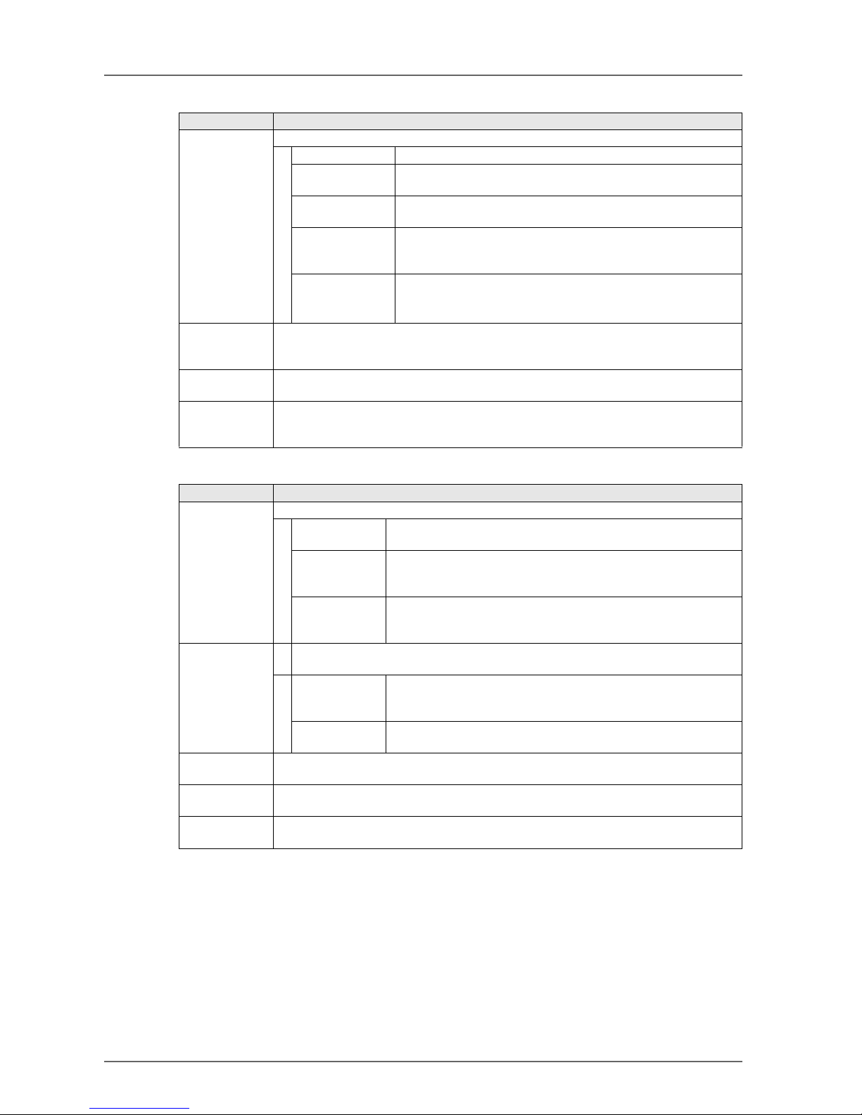
Item Description
Test output
mode
Any of the following five modes can be selected according to the external input device.
Not Used The corresponding test output is not used.
Standard Output Specifies connecting to the input for a muting lamp or PLC. Used
as a monitor output.
Pulse Test Output Specifies connecting a device with a contact output in combination
with the safety input.
Power Supply
Output
Specifies connecting to the power supply terminal of a safety sensor. The voltage supplied from the test output to the I/O power
supply (V, G) is output.
Muting Lamp
Output (terminal
T3 only)
Specifies a muting lamp output.
When the output is ON, disconnection of the muting lamp can be
detected.
Output status
after communications error
Sets the output state of the test output when a communications error occurs.This parameter is enabled when the Test Output Channel Mode is set to Standard Output or Muting
Lamp Output.
Short-circuit
detection
Supported.
Broken wire
detection of external indicator
Supported.
This setting is valid when Test Output Mode is set to Muting Lamp Output.
Item Description
Output channel
mode
Any of the following three modes can be selected according to the external input device.
Not Used The safety output is not used. (External output device not connect-
ed.)
Safety Specifies not outputting the test pulse when the output is ON. Con-
tact between the output signal line and the power supply (positive)
when the output is OFF and ground faults can be detected.
Safety Pulse
Test
Outputs the test pulse when the output is ON. Contact between the
output signal line and the power supply, and short circuits with other
output signal lines can be detected.
Dual channel
mode
The consistency between signals on two channels can be evaluated. Either of the following settings can be selected.
Single Channel Specifies using Single Channel Mode. When Single Channel is set,
the safety output that would be paired for the dual channel parameter is also set to Single Channel Mode.
Dual Channel Specifies using Dual Channel Mode. When both of the safety out-
puts to be paired are normal, the outputs can be turned ON.
Output error
latch time
The OFF status is held for at least the output error latch time (0 to 65,530 ms, in increments of 10 ms) when the individual safety output status turns OFF.
Short-circuit
detection
Supported.
Overcurrent
detection
Supported.
1-4 Description of Safety Functions 27
1-4 Description of Safety Functions
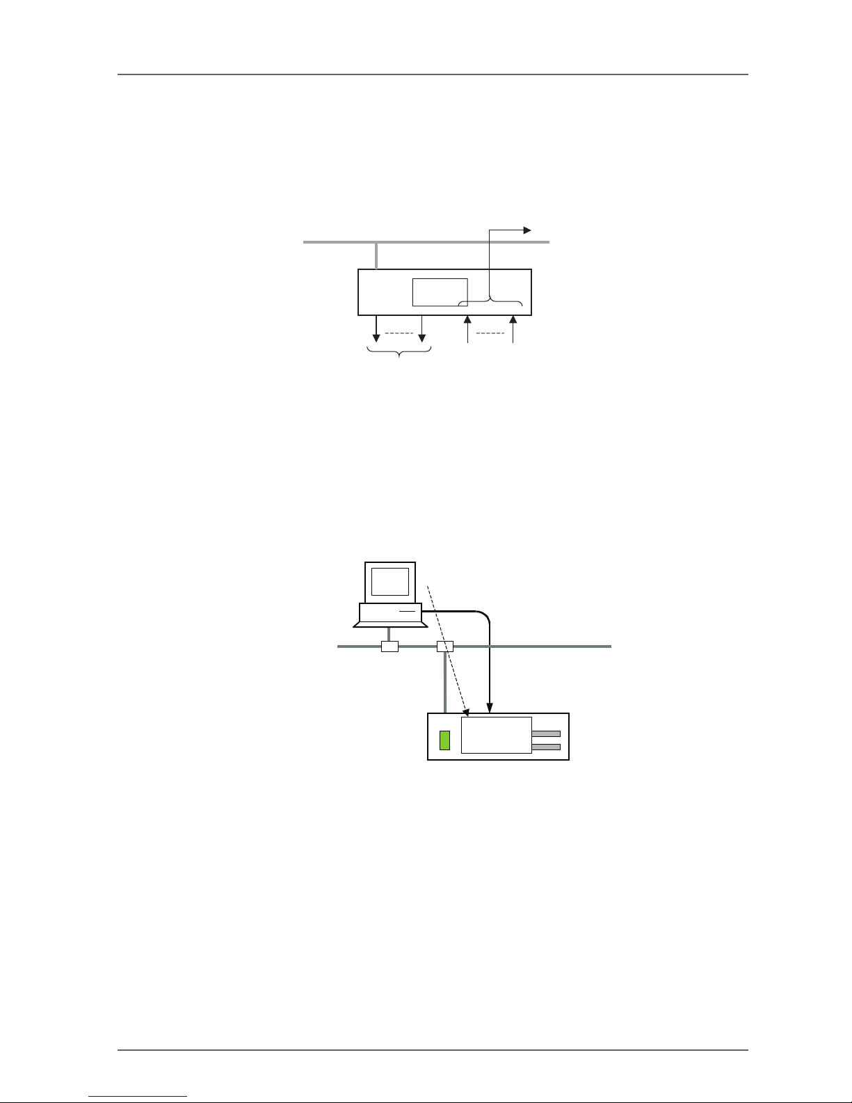
1-4-1 DST1-series Safety I/O Terminals
Safe State
The following status is treated as the safe state by the DST1-series Safety I/O Terminals.
• Safety outputs: OFF
• Output data to network: OFF
Therefore, the DST1-series Safety I/O Terminals must be used for applications in which it enters into safe
state when the safety outputs turn OFF and the output data to the network turns OFF.
Self-diagnosis Functions
Self-diagnosis is performed when the power is turned ON and periodically during operation. If an error occurs, it will be treated as a fatal error (the MS indicator will light in red), and the safety outputs and output
data to the network will turn OFF.
Access Control by Password
After configuration data had been downloaded and verified, the configuration data within the DST1-series
Safety I/O Terminals can be protected by a password.
Note: Refer to the System Configuration Manual (Z905) for password setting.
DeviceNet
Outputs: OFF
Outputs to network: OFF
Inputs
Safe
state
Network Configurator
DST1 Safety I/O Terminal
DeviceNet Network
Password setting
Configuration data
downloaded.
Configuration
data
28 Section 1: Overview
1-4-2 Safety Inputs
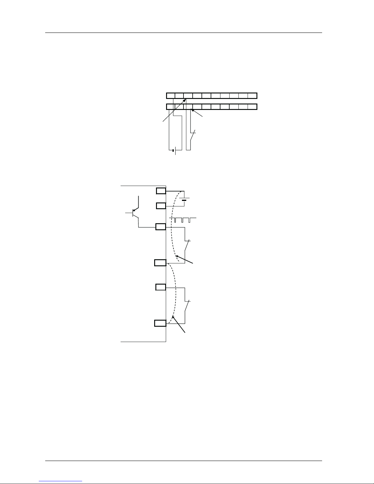
Test Pulse from Test Output
A test output is used in combination with a safety input. Specify the corresponding test output terminal to use
as the test source. The test output terminal is used as a power supply to connect an external input device to
the safety input terminal.
A test pulse is output from the test output terminal to diagnose the internal circuit when the external input
contact turns ON. Using this function, short-circuits between input signal lines and the power supply (positive
side), and short-circuits between input signal lines can be detected.
VV01234567
G G T0 T1 T0 T1 T0 T1 T0 T1
24 V
24 V DC output with test pulse
External contact
Example: DST1-ID12S-1
Here, IN0 and T0 are used in combination
Safety input
terminal
T0
IN0
24 V
0 V
24 V
T1
IN1
V
G
External contact
External contact
Short-circuit between input signal lines
Short-circuit between input signal line and
power supply (positive side)
1-4 Description of Safety Functions 29
If an error is detected, safety input data and individual safety input status will turn OFF.
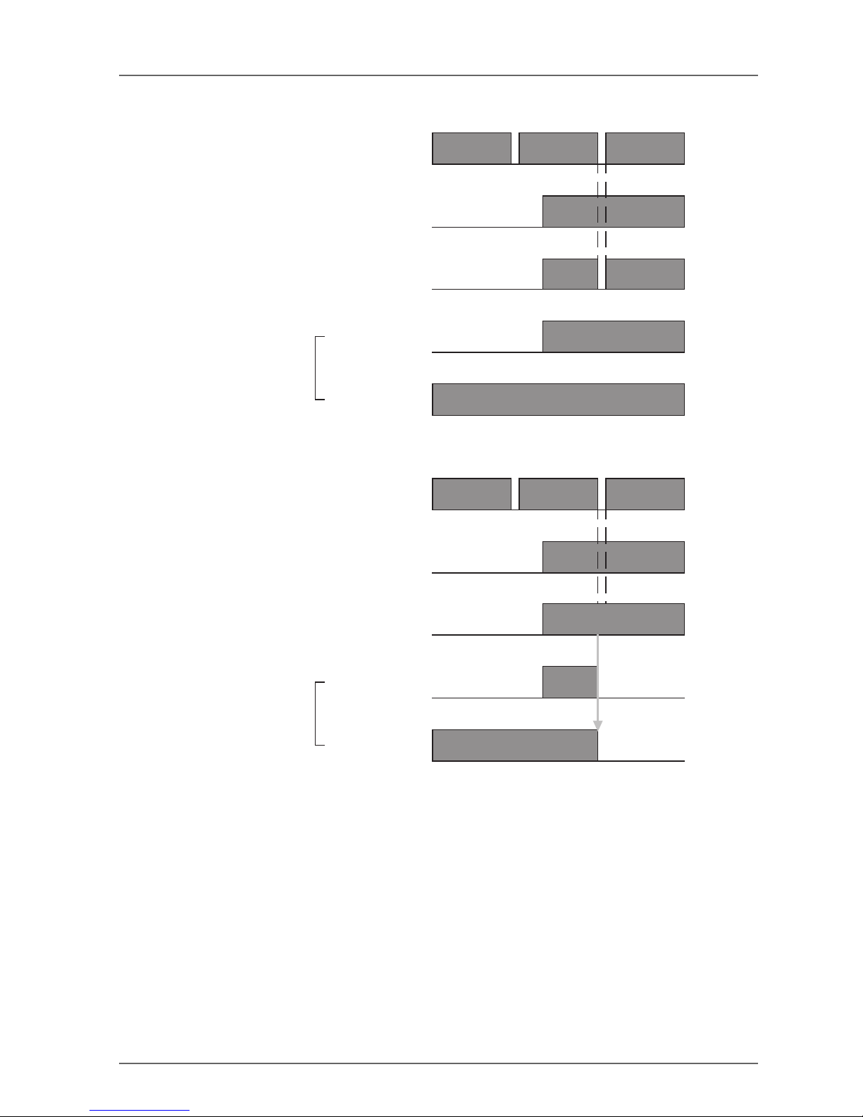
Setting Dual Channel Mode and Discrepancy Time
The consistency between signals on two channels can be evaluated. Either of the following settings can be
selected. This function monitors the time during which there is a discrepancy in the logic between the two
channels set as dual channels. If the length of the discrepancy exceeds the set discrepancy time (0 to 65,530
ms, in increments of 10 ms), the safety input data and the individual safety input status will turn OFF for both
inputs.
IMPORTANT: The dual channel function is used with 2 consecutive inputs that start from even input num-
bers: inputs 0 and 1, inputs 2 and 3, inputs 4 and 5, etc.
T0
External device
24 V
0 V
ON
OFF
IN0
Safety input 0
ON
OFF
ON
OFF
ON
* Normal
OFF
T0
External device
24 V
0 V
ON
OFF
IN0
ON
OFF
ON
OFF
ON
* Error
OFF
Error
Remote
I/O data
Status of safety
input 0
Safety input 0
Remote
I/O data
Status of safety
input 0
30 Section 1: Overview
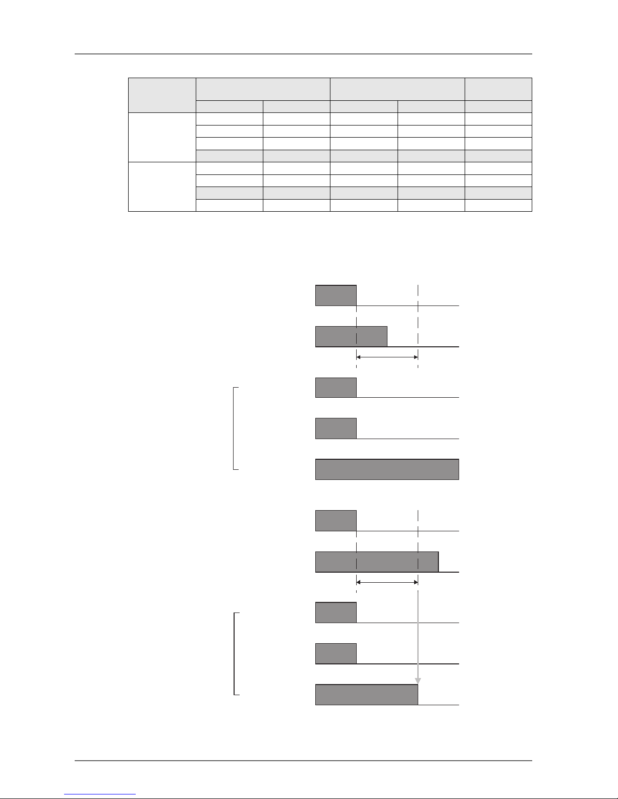
The following table shows the relation between terminal input and remote I/O data.
Dual Channels, Equivalent
The status is treated as normal when both channels are ON or OFF. If one channel is ON and the other channel is OFF, it will be treated as an error, and the safety input data and the individual safety input status will
turn OFF for both inputs.
Dual channel
mode
Input terminals Remote I/O data Meaning of
data
IN0 IN1 Safety input 0 Safety input 1
Dual Channel
Equivalent
0000OFF
0100OFF
1000OFF
1 1 1 1 ON
Dual Channel
Complementary
0001OFF
0101OFF
1 0 1 0 ON
1101OFF
IN0
IN1
ON
OFF
ON
OFF
ON
OFF
ON
OFF
ON
OFF
Discrepancy time
* Normal
IN0
IN1
ON
OFF
ON
OFF
ON
OFF
ON
OFF
ON
OFF
Discrepancy time
* Error
Error
Safety input 0
Safety input 1
Remote
I/O data
Status of safety
input 0 and 1
Safety input 0
Safety input 1
Remote
I/O data
Status of safety
input 0 and 1
 Loading...