

Page 1

SYSTEM CONFIGURATION MANUAL
DeviceNet Safety
NE1A-SCPU01
DST1-ID, DST1-MD, DST1-MR
Cat. No. Z905-E2-01
Page 2

DeviceNet Safety
System Configuration Manual
Produced May 2005
Page 3
1
Notice
OMRON products are manufactured for use according to proper procedures by a qualified operator and only
for the purposes described in this manual.
The following conventions are used to indicate and classify precautions in this manual. Always heed the information provided with them. Failure to heed precautions can result in injury to people or damage to property.
OMRON Product References
All OMRON products are capitalized in this manual. The word "Unit" is also capitalized when it refers to an
OMRON product, regardless of whether or not it appears in the proper name of the product.
The abbreviation "PLC" means Programmable Controller.
Visual Aids
The following headings appear in the left column of the manual to help you locate different types of information.
IMPORTANT: Indicates important information on what to do or not to do to prevent failure to operation,
malfunction, or undesirable effects on product performance.
Note: Indicates information of particular interest for efficient and convenient operation of the product.
1,2,3… Indicates lists of one sort or another, such as procedures, checklists, etc.
Trademarks and Copyrights
DeviceNet and DeviceNet Safety are registered trademarks of the ODVA.
Other product names and company names in this manual are trademarks or registered trademarks of their
respective companies.
© OMRON, 2005
All rights reserved. No part of this publication may be reproduced, stored in a retrieval system, or transmitted,
in any form, or by any means, mechanical, electronic, photocopying, recording, or otherwise, without the prior
written permission of OMRON.
No patent liability is assumed with respect to the use of the information contained herein. Moreover, because
OMRON is constantly striving to improve its high-quality products, the information contained in this manual
is subject to change without notice. Every precaution has been taken in the preparation of this manual. Nevertheless, OMRON assumes no responsibility for errors or omissions. Neither is any liability assumed for
damages resulting from the use of the information contained in this publication.
! WARNING
Indicates a potentially hazardous situation which, if not avoided, will result in minor or
moderate injury, or may result in serious injury or death. Additionally, there may be significant property damage.
•
Indicates general prohibitions for which there is no specific symbol.
•
Indicates general mandatory actions for which there is no specific symbol.
Page 4

2
Page 5

Table of contents 3
Table of contents
Notice . . . . . . . . . . . . . . . . . . . . . . . . . . . . . . . . . . . . . . . . . . . . . . 1
OMRON Product References . . . . . . . . . . . . . . . . . . . . . . . . . . . . . . . . . . 1
Visual Aids . . . . . . . . . . . . . . . . . . . . . . . . . . . . . . . . . . . . . . . . . . . . 1
Trademarks and Copyrights . . . . . . . . . . . . . . . . . . . . . . . . . . . . . . . . . . . 1
About this Manual . . . . . . . . . . . . . . . . . . . . . . . . . . . . . . . . . . . . . . . . 7
Precautions . . . . . . . . . . . . . . . . . . . . . . . . . . . . . . . . . . . . . . . . . . . 9
1 Intended Audience . . . . . . . . . . . . . . . . . . . . . . . . . . . . . . . 9
2 General Precautions. . . . . . . . . . . . . . . . . . . . . . . . . . . . . . . 9
3 Safety Precautions . . . . . . . . . . . . . . . . . . . . . . . . . . . . . . . 11
4 Precautions for Safe Use . . . . . . . . . . . . . . . . . . . . . . . . . . . . 13
Section 1: Overview 15
1-1 DeviceNet Safety System Overview. . . . . . . . . . . . . . . . . . . . . . . . . . . . . . 16
1-1-1 About DeviceNet Safety . . . . . . . . . . . . . . . . . . . . . . . . . . . . . . 16
1-2 Safety Network Controller Overview . . . . . . . . . . . . . . . . . . . . . . . . . . . . . 17
1-2-1 About the NE1A Safety Network Controller . . . . . . . . . . . . . . . . . . . . 17
1-2-2 Safety Network Controller Features . . . . . . . . . . . . . . . . . . . . . . . . 17
1-2-3 Standard Models . . . . . . . . . . . . . . . . . . . . . . . . . . . . . . . . . . 18
1-3 Safety I/O Terminal Overview . . . . . . . . . . . . . . . . . . . . . . . . . . . . . . . . .19
1-3-1 About the DST1-series Safety I/O Terminals . . . . . . . . . . . . . . . . . . . 19
1-3-2 Safety I/O Terminal Features . . . . . . . . . . . . . . . . . . . . . . . . . . . 19
1-3-3 Standard Models . . . . . . . . . . . . . . . . . . . . . . . . . . . . . . . . . . 20
1-4 Network Configurator Overview. . . . . . . . . . . . . . . . . . . . . . . . . . . . . . . . 21
1-4-1 About the Network Configurator . . . . . . . . . . . . . . . . . . . . . . . . . . 21
1-4-2 Network Configurator Features . . . . . . . . . . . . . . . . . . . . . . . . . . 21
1-4-3 System Requirements . . . . . . . . . . . . . . . . . . . . . . . . . . . . . . . 22
1-4-4 Standard Models . . . . . . . . . . . . . . . . . . . . . . . . . . . . . . . . . . 22
1-5 Basic System Startup Procedure . . . . . . . . . . . . . . . . . . . . . . . . . . . . . . . 23
1-5-1 System Design and Programming . . . . . . . . . . . . . . . . . . . . . . . . . 23
1-5-2 Installation and Wiring . . . . . . . . . . . . . . . . . . . . . . . . . . . . . . . 23
1-5-3 Configuration . . . . . . . . . . . . . . . . . . . . . . . . . . . . . . . . . . . . 24
1-5-4 User Test. . . . . . . . . . . . . . . . . . . . . . . . . . . . . . . . . . . . . . 24
Section 2: Basic Operation of the Network Configurator 25
2-1 Network Configurator Startup and Main Window . . . . . . . . . . . . . . . . . . . . . . 27
2-1-1 Starting and Exiting the Network Configurator . . . . . . . . . . . . . . . . . . . 27
2-1-2 Checking the Version . . . . . . . . . . . . . . . . . . . . . . . . . . . . . . . 28
2-1-3 Main Window. . . . . . . . . . . . . . . . . . . . . . . . . . . . . . . . . . . . 28
2-2 Menu List . . . . . . . . . . . . . . . . . . . . . . . . . . . . . . . . . . . . . . . . . . . . 29
2-2-1 File Menu . . . . . . . . . . . . . . . . . . . . . . . . . . . . . . . . . . . . . 29
2-2-2 Edit Menu . . . . . . . . . . . . . . . . . . . . . . . . . . . . . . . . . . . . . 29
2-2-3 View Menu . . . . . . . . . . . . . . . . . . . . . . . . . . . . . . . . . . . . . 29
2-2-4 Network Menu . . . . . . . . . . . . . . . . . . . . . . . . . . . . . . . . . . . 29
2-2-5 Device Menu . . . . . . . . . . . . . . . . . . . . . . . . . . . . . . . . . . . . 30
2-2-6 EDS File Menu . . . . . . . . . . . . . . . . . . . . . . . . . . . . . . . . . . . 31
2-2-7 Tools Menu . . . . . . . . . . . . . . . . . . . . . . . . . . . . . . . . . . . . 31
2-2-8 Option Menu . . . . . . . . . . . . . . . . . . . . . . . . . . . . . . . . . . . . 31
2-2-9 Help Menu . . . . . . . . . . . . . . . . . . . . . . . . . . . . . . . . . . . . . 31
2-3 Connecting to the Network . . . . . . . . . . . . . . . . . . . . . . . . . . . . . . . . . .32
2-3-1 Network Connection via USB Port . . . . . . . . . . . . . . . . . . . . . . . . . 32
2-3-2 Network Connection via DeviceNet Interface Card . . . . . . . . . . . . . . . . 33
Page 6

4 Table of contents
2-4 Creating a Virtual Network . . . . . . . . . . . . . . . . . . . . . . . . . . . . . . . . . . 34
2-4-1 Creating a New Virtual Network . . . . . . . . . . . . . . . . . . . . . . . . . 34
2-4-2 Network Numbers. . . . . . . . . . . . . . . . . . . . . . . . . . . . . . . . . 34
2-4-3 Adding Devices . . . . . . . . . . . . . . . . . . . . . . . . . . . . . . . . . . 35
2-4-4 Deleting Devices . . . . . . . . . . . . . . . . . . . . . . . . . . . . . . . . . 36
2-4-5 Changing the Node Address . . . . . . . . . . . . . . . . . . . . . . . . . . . 37
2-4-6 Changing Device Comments . . . . . . . . . . . . . . . . . . . . . . . . . . . 37
2-5 Saving and Reading Network Configuration Files . . . . . . . . . . . . . . . . . . . . . 38
2-5-1 Password Protection of the Network Configuration File . . . . . . . . . . . . . 38
2-5-2 Saving the Network Configuration File . . . . . . . . . . . . . . . . . . . . . . 38
2-5-3 Reading a Network Configuration File . . . . . . . . . . . . . . . . . . . . . . 39
2-5-4 Protect Mode . . . . . . . . . . . . . . . . . . . . . . . . . . . . . . . . . . . 39
2-6 Device Password Protection . . . . . . . . . . . . . . . . . . . . . . . . . . . . . . . . . 40
2-6-1 Setting a Device Password . . . . . . . . . . . . . . . . . . . . . . . . . . . . 40
2-6-2 Forgotten Device Passwords . . . . . . . . . . . . . . . . . . . . . . . . . . . 40
2-7 Device Parameters and Properties . . . . . . . . . . . . . . . . . . . . . . . . . . . . . 41
2-7-1 Editing Device Parameters . . . . . . . . . . . . . . . . . . . . . . . . . . . . 41
2-7-2 Uploading Device Parameters . . . . . . . . . . . . . . . . . . . . . . . . . . 41
2-7-3 Downloading Device Parameters . . . . . . . . . . . . . . . . . . . . . . . . . 41
2-7-4 Device Properties . . . . . . . . . . . . . . . . . . . . . . . . . . . . . . . . . 43
2-8 Parameter Verification . . . . . . . . . . . . . . . . . . . . . . . . . . . . . . . . . . . . 45
2-8-1 Device Parameter Verification . . . . . . . . . . . . . . . . . . . . . . . . . . 45
2-9 Configuration Lock . . . . . . . . . . . . . . . . . . . . . . . . . . . . . . . . . . . . . . 48
2-9-1 Locking the Device Configuration. . . . . . . . . . . . . . . . . . . . . . . . . 48
2-9-2 Unlocking the Device Configuration . . . . . . . . . . . . . . . . . . . . . . . 48
2-10 Device Reset and Status Change . . . . . . . . . . . . . . . . . . . . . . . . . . . . . . 49
2-10-1 Reset Types . . . . . . . . . . . . . . . . . . . . . . . . . . . . . . . . . . . 49
2-10-2 Resetting Devices . . . . . . . . . . . . . . . . . . . . . . . . . . . . . . . . 50
2-10-3 Reset Types and Device Status . . . . . . . . . . . . . . . . . . . . . . . . . 50
2-10-4 Changing Device Status . . . . . . . . . . . . . . . . . . . . . . . . . . . . . 51
Section 3: Constructing a Safety Network 53
3-1 Applications . . . . . . . . . . . . . . . . . . . . . . . . . . . . . . . . . . . . . . . . . . 54
3-1-1 Establishing a New Safety Network . . . . . . . . . . . . . . . . . . . . . . . 54
3-1-2 Changing an Established Safety Network . . . . . . . . . . . . . . . . . . . . 56
3-2 Verifying the Network Bandwidth . . . . . . . . . . . . . . . . . . . . . . . . . . . . . . 59
3-2-1 Checking the Network Bandwidth Used for Safety I/O Communications . . . . . 59
3-2-2 Allocating Network Bandwidth . . . . . . . . . . . . . . . . . . . . . . . . . . 60
3-2-3 Example of EPI Calculation . . . . . . . . . . . . . . . . . . . . . . . . . . . . 61
3-3 Calculating and Verifying the Maximum Reaction Time . . . . . . . . . . . . . . . . . . 63
3-3-1 Concept of Reaction Time . . . . . . . . . . . . . . . . . . . . . . . . . . . . 63
3-3-2 Calculating the Maximum Reaction Time. . . . . . . . . . . . . . . . . . . . . 64
3-3-3 Verifying the Maximum Reaction Time . . . . . . . . . . . . . . . . . . . . . . 67
Page 7

Table of contents 5
Section 4: Editing Safety I/O Terminal Parameters 69
4-1 Editing Parameters . . . . . . . . . . . . . . . . . . . . . . . . . . . . . . . . . . . . . . . 70
4-1-1 Parameter Groups . . . . . . . . . . . . . . . . . . . . . . . . . . . . . . . . . 70
4-1-2 General Parameter Group . . . . . . . . . . . . . . . . . . . . . . . . . . . . . 71
4-1-3 Safety Input Parameter Groups . . . . . . . . . . . . . . . . . . . . . . . . . . 73
4-1-4 Test Output Parameter Groups . . . . . . . . . . . . . . . . . . . . . . . . . . 75
4-1-5 Safety Output Parameter Groups . . . . . . . . . . . . . . . . . . . . . . . . . 76
4-1-6 Operation Time Parameter Groups . . . . . . . . . . . . . . . . . . . . . . . . 77
Section 5: Editing Safety Network Controller Parameters 79
5-1 Safety Connection Settings . . . . . . . . . . . . . . . . . . . . . . . . . . . . . . . . . .80
5-1-1 Registering Safety Slaves . . . . . . . . . . . . . . . . . . . . . . . . . . . . . 80
5-1-2 Setting Safety Connection Parameters . . . . . . . . . . . . . . . . . . . . . . 82
5-2 Safety Slave Settings . . . . . . . . . . . . . . . . . . . . . . . . . . . . . . . . . . . . . 84
5-2-1 Registering I/O Assemblies for Safety Slaves . . . . . . . . . . . . . . . . . . . 84
5-2-2 Setting Assembly Data . . . . . . . . . . . . . . . . . . . . . . . . . . . . . . . 85
5-3 Standard Slave Settings . . . . . . . . . . . . . . . . . . . . . . . . . . . . . . . . . . . . 87
5-3-1 Registering I/O Assemblies for Standard Slaves . . . . . . . . . . . . . . . . . 87
5-3-2 Setting Slave Input Data in Idle State . . . . . . . . . . . . . . . . . . . . . . . 88
5-3-3 Setting Assembly Data . . . . . . . . . . . . . . . . . . . . . . . . . . . . . . . 88
5-4 Local I/O Settings . . . . . . . . . . . . . . . . . . . . . . . . . . . . . . . . . . . . . . . 90
5-4-1 Setting Safety Inputs . . . . . . . . . . . . . . . . . . . . . . . . . . . . . . . . 90
5-4-2 Setting Test Outputs . . . . . . . . . . . . . . . . . . . . . . . . . . . . . . . . 92
5-4-3 Setting Safety Outputs . . . . . . . . . . . . . . . . . . . . . . . . . . . . . . . 93
5-5 Setting the Operation Modes and Confirming the Cycle Time . . . . . . . . . . . . . . . 95
5-5-1 Setting the NE1A-SCPU01 Operation Modes . . . . . . . . . . . . . . . . . . . 95
5-5-2 Confirming the Cycle Time . . . . . . . . . . . . . . . . . . . . . . . . . . . . . 96
Section 6: Programming the Safety Network Controller 97
6-1 Starting and Exiting the Logic Editor . . . . . . . . . . . . . . . . . . . . . . . . . . . . . 98
6-1-1 Starting the Logic Editor . . . . . . . . . . . . . . . . . . . . . . . . . . . . . . 98
6-1-2 Exiting the Logic Editor . . . . . . . . . . . . . . . . . . . . . . . . . . . . . . 99
6-2 Menu Commands. . . . . . . . . . . . . . . . . . . . . . . . . . . . . . . . . . . . . . . 100
6-2-1 File Menu . . . . . . . . . . . . . . . . . . . . . . . . . . . . . . . . . . . . 100
6-2-2 Edit Menu . . . . . . . . . . . . . . . . . . . . . . . . . . . . . . . . . . . . 100
6-2-3 View Menu . . . . . . . . . . . . . . . . . . . . . . . . . . . . . . . . . . . . 100
6-2-4 Function Menu . . . . . . . . . . . . . . . . . . . . . . . . . . . . . . . . . . 100
6-2-5 Page Menu . . . . . . . . . . . . . . . . . . . . . . . . . . . . . . . . . . . . 100
6-3 Programming . . . . . . . . . . . . . . . . . . . . . . . . . . . . . . . . . . . . . . . . . 101
6-3-1 Workspace . . . . . . . . . . . . . . . . . . . . . . . . . . . . . . . . . . . . 101
6-3-2 Programming Using Function Blocks . . . . . . . . . . . . . . . . . . . . . . 101
6-3-3 Saving the Program . . . . . . . . . . . . . . . . . . . . . . . . . . . . . . . 108
6-3-4 Updating the Program . . . . . . . . . . . . . . . . . . . . . . . . . . . . . . 108
6-3-5 Monitoring the Program . . . . . . . . . . . . . . . . . . . . . . . . . . . . . 109
Page 8

6 Table of contents
Section 7: Monitoring Devices 111
7-1 Monitoring Functions . . . . . . . . . . . . . . . . . . . . . . . . . . . . . . . . . . . . . 112
7-1-1 Monitoring Status . . . . . . . . . . . . . . . . . . . . . . . . . . . . . . . . . 112
7-1-2 Monitoring Safety Connections . . . . . . . . . . . . . . . . . . . . . . . . . . 113
7-1-3 Monitoring Parameters . . . . . . . . . . . . . . . . . . . . . . . . . . . . . . 115
7-1-4 Monitoring the Error History . . . . . . . . . . . . . . . . . . . . . . . . . . . 116
7-2 Maintenance Functions of DST1-series Safety I/O Terminals . . . . . . . . . . . . . . . 118
7-2-1 Network Power Supply Voltage Monitor . . . . . . . . . . . . . . . . . . . . . 118
7-2-2 Monitoring the Run Hours . . . . . . . . . . . . . . . . . . . . . . . . . . . . 120
7-2-3 Last Maintenance Date . . . . . . . . . . . . . . . . . . . . . . . . . . . . . . 122
7-2-4 Monitoring the Contact Operation Counters . . . . . . . . . . . . . . . . . . . 124
7-2-5 Monitoring the Total ON Times . . . . . . . . . . . . . . . . . . . . . . . . . . 126
7-2-6 Monitoring the Operation Time . . . . . . . . . . . . . . . . . . . . . . . . . . 129
Appendices 133
A Connecting to the Network via a CS/CJ-series PLC . . . . . . . . . . . . . . . . . . . . 135
A-1 Connecting to the DeviceNet Network . . . . . . . . . . . . . . . . . . . . . . 135
A-2 Specifying the Connection Interface . . . . . . . . . . . . . . . . . . . . . . . 136
B Editing CS/CJ-series DeviceNet Unit Parameters . . . . . . . . . . . . . . . . . . . . . 143
B-1 Setting the Unit Functions . . . . . . . . . . . . . . . . . . . . . . . . . . . . 143
B-2 Master Parameter Overview . . . . . . . . . . . . . . . . . . . . . . . . . . . 143
B-3 I/O Allocation Using the Parameter Wizard (Simple I/O Allocation) . . . . . . . 147
B-4 Manual I/O Allocation . . . . . . . . . . . . . . . . . . . . . . . . . . . . . . . 151
B-5 Advanced Settings: Connection, Communications Cycle Time,
Slave Function Settings, etc. . . . . . . . . . . . . . . . . . . . . . . . . . . . 156
C EDS File Management . . . . . . . . . . . . . . . . . . . . . . . . . . . . . . . . . . . .161
C-1 Installing EDS Files . . . . . . . . . . . . . . . . . . . . . . . . . . . . . . . . 161
C-2 Creating EDS Files . . . . . . . . . . . . . . . . . . . . . . . . . . . . . . . . 162
C-3 Deleting EDS Files . . . . . . . . . . . . . . . . . . . . . . . . . . . . . . . . 163
C-4 Saving EDS Files . . . . . . . . . . . . . . . . . . . . . . . . . . . . . . . . . 163
C-5 Searching EDS Files . . . . . . . . . . . . . . . . . . . . . . . . . . . . . . . 164
C-6 EDS File Properties. . . . . . . . . . . . . . . . . . . . . . . . . . . . . . . . 164
D Using General-purpose Tools to Set Devices. . . . . . . . . . . . . . . . . . . . . . . . 165
D-1 Setting Device Parameters by Specifying Class and Instance . . . . . . . . . . 165
D-2 Setting the Node Addresses and Baud Rates via the Network . . . . . . . . . . 167
E Using the Password Recovery Tool . . . . . . . . . . . . . . . . . . . . . . . . . . . . . 169
Glossary 173
Index 175
Revision History 177
Page 9
7
About this Manual
This manual describes the configuration of the DeviceNet Safety system.
Please read this manual carefully and be sure you understand the information provided before attempting to
configure a DeviceNet Safety system. Be sure to read the precautions provided in the following section.
The following manuals provide information on the DeviceNet and DeviceNet Safety.
DeviceNet Safety System Configuration Manual (this manual) (Z905)
This manual explains how to configure the DeviceNet Safety system using the Network Configurator.
NE1A-SCPU01 Safety Network Controller Operation Manual (Z906)
This manual describes the specifications, functions, and usage of the NE1A-SCPU01.
DST1-series Safety I/O Terminal Operation Manual (Z904)
This manual describes the specifications, functions, and usage of the DST1 series.
DeviceNet Operation Manual (W267)
This manual describes the construction and connection of a DeviceNet network. It provides detailed information on the installation and specifications of cables, connectors, and other peripheral equipment used in the
network, and on the supply of communications power. Obtain this manual and gain a firm understanding of
its contents before using a DeviceNet system.
Read and Understand this Manual
Please read and understand this manual before using the product. Please consult your OMRON representative if you have any questions or comments.
Warranty and Limitations of Liability
! WARNING
Failure to read and understand the information provided in this manual may result in personal injury or
death, damage to the product, or product failure. Please read each section in its entirety and be sure you
understand the information provided in the section and related sections before attempting any of the procedures or operations given.
WARRANTY
OMRON's exclusive warranty is that the products are free from defects in materials and workmanship for a
period of one year (or other period if specified) from date of sale by OMRON.
OMRON MAKES NO WARRANTY OR REPRESENTATION, EXPRESS OR IMPLIED, REGARDING NONINFRINGEMENT, MERCHANTABILITY, OR FITNESS FOR PARTICULAR PURPOSE OF THE
PRODUCTS. ANY BUYER OR USER ACKNOWLEDGES THAT THE BUYER OR USER ALONE HAS
DETERMINED THAT THE PRODUCTS WILL SUITABLY MEET THE REQUIREMENTS OF THEIR
INTENDED USE. OMRON DISCLAIMS ALL OTHER WARRANTIES, EXPRESS OR IMPLIED.
LIMITATIONS OF LIABILITY
OMRON SHALL NOT BE RESPONSIBLE FOR SPECIAL, INDIRECT, OR CONSEQUENTIAL DAMAGES,
LOSS OF PROFITS OR COMMERCIAL LOSS IN ANY WAY CONNECTED WITH THE PRODUCTS,
WHETHER SUCH CLAIM IS BASED ON CONTRACT, WARRANTY, NEGLIGENCE, OR STRICT
LIABILITY.
In no event shall the responsibility of OMRON for any act exceed the individual price of the product on which
liability is asserted.
IN NO EVENT SHALL OMRON BE RESPONSIBLE FOR WARRANTY, REPAIR, OR OTHER CLAIMS
REGARDING THE PRODUCTS UNLESS OMRON'S ANALYSIS CONFIRMS THAT THE PRODUCTS
WERE PROPERLY HANDLED, STORED, INSTALLED, AND MAINTAINED AND NOT SUBJECT TO
CONTAMINATION, ABUSE, MISUSE, OR INAPPROPRIATE MODIFICATION OR REPAIR.
Page 10

8
Application Considerations
Disclaimers
SUITABILITY FOR USE
OMRON shall not be responsible for conformity with any standards, codes, or regulations that apply to the
combination of products in the customer's application or use of the products.
At the customer's request, OMRON will provide applicable third party certification documents identifying ratings and limitations of use that apply to the products. This information by itself is not sufficient for a complete
determination of the suitability of the products in combination with the end product, machine, system, or other application or use.
The following are some examples of applications for which particular attention must be given. This is not
intended to be an exhaustive list of all possible uses of the products, nor is it intended to imply that the uses
listed may be suitable for the products:
• Outdoor use, uses involving potential chemical contamination or electrical interference, or conditions
or uses not described in this manual.
• Nuclear energy control systems, combustion systems, railroad systems, aviation systems, medical
equipment, amusement machines, vehicles, safety equipment, and installations subject to separate
industry or government regulations.
• Systems, machines, and equipment that could present a risk to life or property.
Please know and observe all prohibitions of use applicable to the products.
NEVER USE THE PRODUCTS FOR AN APPLICATION INVOLVING SERIOUS RISK TO LIFE OR PROP-
ERTY WITHOUT ENSURING THAT THE SYSTEM AS A WHOLE HAS BEEN DESIGNED TO ADDRESS
THE RISKS, AND THAT THE OMRON PRODUCTS ARE PROPERLY RATED AND INSTALLED FOR THE
INTENDED USE WITHIN THE OVERALL EQUIPMENT OR SYSTEM.
PROGRAMMABLE PRODUCTS
OMRON shall not be responsible for the user's programming of a programmable product, or any consequence thereof.
CHANGE IN SPECIFICATIONS
Product specifications and accessories may be changed at any time based on improvements and other reasons.
It is our practice to change model numbers when published ratings or features are changed, or when significant construction changes are made. However, some specifications of the products may be changed without any notice. When in doubt, special model numbers may be assigned to fix or establish key specifications
for your application on your request. Please consult with your OMRON representative at any time to confirm
actual specifications of purchased products.
DIMENSIONS AND WEIGHTS
Dimensions and weights are nominal and are not to be used for manufacturing purposes, even when tolerances are shown.
PERFORMANCE DATA
Performance data given in this manual is provided as a guide for the user in determining suitability and does
not constitute a warranty. It may represent the result of OMRON's test conditions, and the users must correlate it to actual application requirements. Actual performance is subject to the OMRON Warranty and Limitations of Liability.
ERRORS AND OMISSIONS
The information in this manual has been carefully checked and is believed to be accurate; however, no responsibility is assumed for clerical, typographical, or proofreading errors, or omissions.
Page 11

9
Precautions
1 Intended Audience
This manual is intended for the following personnel, who must have knowledge of electrical systems (an electrical engineer or the equivalent).
• Personnel in charge of introducing FA and safety systems into production facilities
• Personnel in charge of designing FA and safety systems
• Personnel in charge of managing FA facilities
• Personnel who have the qualifications, authority, and obligation to provide safety during each of the following product phases: mechanical design, installation, operation, maintenance, and disposal
2 General Precautions
The user must operate the product according to the performance specifications described in the operation
manuals.
Before using the product under conditions which are not described in the manual or applying the product to
nuclear control systems, railroad systems, aviation systems, vehicles, combustion systems, medical equipment, amusement machines, safety equipment, and other systems, machines, and equipment that may have
a serious influence on lives and property if used improperly, consult your OMRON representative.
Make sure that the ratings and performance characteristics of the product are sufficient for the systems, machines, and equipment, and be sure to provide the systems, machines, and equipment with double safety
mechanisms.
This manual provides information for programming and operating the Unit. Be sure to read this manual before
attempting to use the Unit and keep this manual close at hand for reference during operation.
Page 12

10
! WARNING
This is the System Configuration Manual for DeviceNet Safety Systems. Heed the following items during
system construction to ensure that safety-related components are configured in a manner that allows the
system functions to operate sufficiently.
Risk Assessment
The proper use of safety devices described in this Manual as it relates to installation conditions and mechanical performance and functions is a prerequisite for their use. When selecting or using a safety device,
risk assessment must be conducted with the aim of identifying potential danger factors in equipment or facilities in which the safety device is to be applied, during the development stage of the equipment or facilities. Suitable safety devices must be selected under the guidance of a sufficient risk assessment system.
An insufficient risk assessment system may lead to the selection of unsuitable safety devices.
• Typical related international standards: ISO 14121, Safety of Machinery -- Principles of Risk Assessment
Safety Measures
When using safety devices to build systems containing safety-related components for equipment or facilities, the system must be designed with the full understanding of and conformance to international standards, such as those listed below, and/or standards in related industries.
• Typical related international standards: ISO/DIS 12100, Safety of Machinery -- Basic Concepts and
General Principles for Design
IEC 61508, Safety Standard for Safety Instrumented Systems (Functional Safety of Electrical/Electronic/Programmable Electronic Safety-related Systems)
Role of Safety Devices
The safety devices are provided with safety functions and mechanisms as stipulated in relevant standards,
but suitable designs must be used to allow these functions and mechanisms to operate properly inside system constructions containing safety-related components. Build systems that enable these functions and
mechanisms to perform properly, based on a full understanding of their operation.
• Typical related international standards: ISO 14119, Safety of Machinery -- Interlocking Devices Associated with Guards -- Principles of Design and Selection
Installation of Safety Devices
The construction and installation of systems with safety-related components for equipment or facilities must
be performed by technicians who have received suitable training.
• Typical related international standards: ISO/DIS 12100, Safety of Machinery -- Basic Concepts and
General Principles for Design
IEC 61508, Safety Standard for Safety Instrumented Systems (Functional Safety of Electrical/Electronic/Programmable Electronic Safety-related Systems)
Complying with Laws and Regulations
The safety devices conform to the relevant regulations and standards, but make sure that they are used in
compliance with local regulations and standards for the equipment or facilities in which they are applied.
• Typical related international standards: IEC 60204, Safety of Machinery -- Electrical Equipment of
Machines
Observing Precautions for Use
When putting the selected safety devices to actual use, heed the specifications and precautions in this Manual and those in the Operation Manuals that comes with the products. Using the products in a manner that
deviates from these specifications and precautions will lead to unexpected failures in equipment or devices,
and to damages that result from such failures, due to insufficient operating functions in safety-related components.
Moving or Transferring Devices or Equipment
When moving or transferring devices or equipment, be sure to include this Manual to ensure that the person
to whom the device or equipment is being moved or transferred will be able to operate the system properly.
• Typical related international standards: ISO/DIS 12100 ISO, Safety of Machinery -- Basic Concepts
and General Principles for Design IEC 61508, Safety Standard for Safety Instrumented Systems
(Functional Safety of Electrical/Electronic/Programmable Electronic Safety-related Systems)
Page 13
11
3 Safety Precautions
! WARNING
Safety functions may be impaired and serious injury may occasionally occur. Do not use the
test outputs of the products as safety outputs.
Safety functions may be impaired and serious injury may occasionally occur. Do not use DeviceNet standard I/O data or explicit message data as safety signals.
Safety functions may be impaired and serious injury may occasionally occur. Do not use the
indicators on the products for safety operations.
Serious injury may possibly occur due to breakdown of safety outputs or test outputs. Do not
connect loads beyond the rated value to the safety outputs or test outputs.
Safety functions may be impaired and serious injury may occasionally occur. Wire the output
lines and 24-VDC line so that they will not touch each other to prevent a load from turning ON
due to a short-circuit with the 24-VDC line.
Safety functions may be impaired and serious injury may occasionally occur. Ground the 0V side of the external power supply to prevent an output from turning ON due to a ground fault
in a safety output or test output.
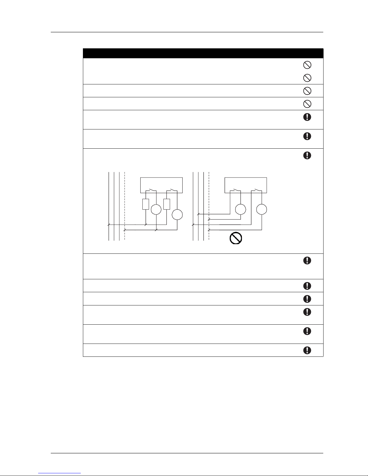
Safety functions may be impaired and serious injury may occasionally occur. For the DST1MRD08SL-1, apply only one AC line phase to the relay output.
Safety functions may be impaired and serious injury may occasionally occur. For the DST1MRD08SL-1, insert a fuse rated at 3.15 A or less for each output terminal to protect safety
output contacts from welding. Confirm the fuse selection with the fuse manufacturer to ensure
the dependability of the characteristics of the connected load.
Safety functions may be impaired, and serious injury may occasionally occur. Before connecting a device to the network, clear the previous configuration data.
Safety functions may be impaired and serious injury may occasionally occur. Before connecting a device to the network, configure the appropriate node address and the baud rate.
Safety functions may be impaired and serious injury may occasionally occur. Before operating the system, conduct user testing to confirm if the configuration data of all the devices and
their operations are correct.
Safety functions may be impaired, and serious injury may occasionally occur. When replacing a device, confirm that the replacement device is appropriately configured and operates
properly.
Serious injury may possibly occur due to loss of required safety functions. Use appropriate
components or devices according to the requirements given in the following table.
L1 L2 L3 N
DST1-
MRD08SL-1
L1 L2 L3 N
DST1-
MRD08SL-1
Fuse
Fuse
Load
Load LoadLoad
Correct
Incorrect
Page 14

12
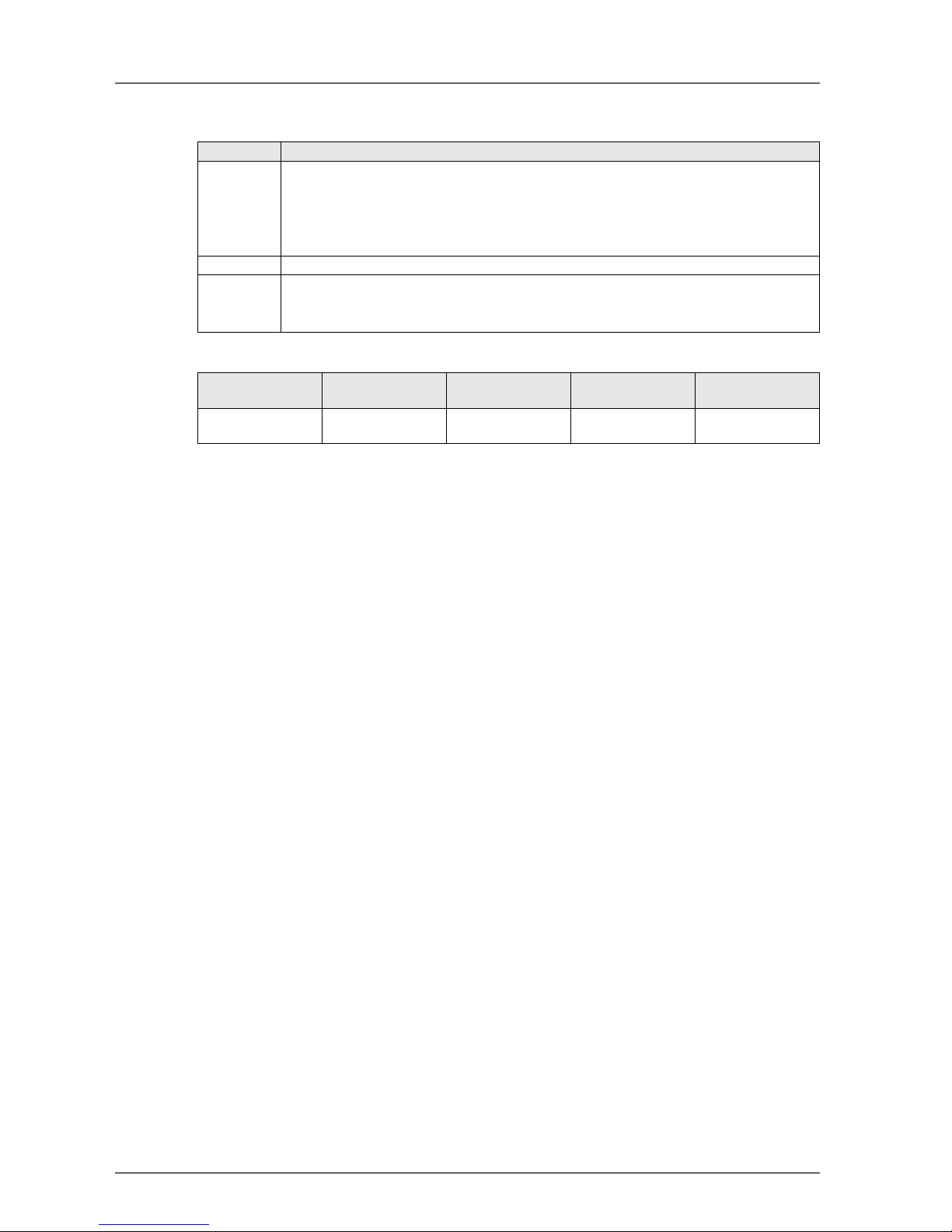
Controlling devices Requirements
Emergency stop switch Use approved devices with a direct opening mechanism compliant with
IEC/EN 60947-5-1.
Door interlocking switch or limit
switch
Use approved devices with a direct opening mechanism compliant with
IEC/EN 60947-5-1 and capable of switching micro-loads of 4 mA at 24
VDC.
Safety sensor Use approved devices compliant with the relevant product standards,
regulations, and rules in the country where they are used.
Relay with forcibly guided contacts Use approved devices with forcibly guided contacts compliant with EN
50205. For feedback, use devices with contacts capable of switching
micro-loads of 4 mA at 24 VDC.
Contactor Use contactors with a forcibly guided mechanism and monitor the aux-
iliary NC contact to detect contactor failures. For feedback, use devices
with contacts capable of switching micro-loads of 4 mA at 24 VDC.
Other devices Evaluate whether devices used are appropriate to satisfy the require-
ments of the safety category level.
Page 15

13
4 Precautions for Safe Use
Handling
Do not drop the products or subject them to excessive vibration or impact. Doing so may result in error or
malfunction.
Installation and Storage
Do not install or store the products in the following locations:
• Locations subject to direct sunlight
• Locations subject to temperatures or humidity outside the range specified in the specifications
• Locations subject to condensation as the result of severe changes in temperature
• Locations subject to corrosive or flammable gases
• Locations subject to dust (especially iron dust) or salts
• Locations subject to water, oil, or chemicals
• Locations subject to shock or vibration outside the range specified in the specifications
Take appropriate and sufficient measures when installing systems in the following locations. Inappropriate
and insufficient measures may result in malfunction.
• Locations subject to static electricity or other forms of noise
• Locations subject to strong electromagnetic fields
• Locations subject to possible exposure to radioactivity
• Locations close to power supplies
Mounting
Confirim the operating suggestions provided in the operation manual for each product before installation and
mounting.
Wiring
• Use the following wires to connect external I/O devices to the products.
• Turn OFF the power supply before starting any wiring operations. Not doing so may result in unexpected operation of external devices connected to the products.
• Properly apply the specified voltage to the product inputs. Applying an inappropriate DC voltage or any
AC voltage may cause reduced safety functions, damage to the products, or a fire.
• Do not wire cables for communications and I/O signals near high-voltage lines or power lines.
• Be careful not to get your fingers caught when attaching connectors to the plugs on the products.
• Tighten the DeviceNet connector to the appropriate torque (0.25 to 0.3 Nm).
• Incorrect wiring may reduce safety functions. Perform all wiring correctly and check operation prior to
using the products.
• Remove the dust-preventive label after completing wiring to ensure proper heat dissipation.
Selecting a Power Supply
Use a DC power supply satisfying the following requirements.
• The secondary circuits of the DC power supply must be isolated from the primary circuit by double insulation or reinforced insulation.
• The DC power supply must satisfy the requirements for class 2 circuits or limited voltage/current circuits
defined in UL 508.
• The output hold time must be 20 ms or longer.
Periodic Inspections and Maintenance
• Turn OFF the power supply before replacing the products. Not doing so may result in unexpected operation of external devices connected to the products.
• Do not disassemble, repair, or modify the products. Doing so may impair the safety functions.
Solid wire 0.2 to 2.5 mm2 (AWG 24 to AWG 12)
Stranded (flexible) wire 0.34 to 1.5 mm2 (AWG 22 to AWG 16)
Stranded wires should be prepared by attaching ferrules with plastic insulation collars (DIN 46228-4 standard compatible) before connecting them.
Page 16

14
Disposal
• If you disassemble the products for disposal, be careful not to injure yourself.
Page 17

15
Section 1: Overview
1-1 DeviceNet Safety System Overview. . . . . . . . . . . . . . . . . . . . . . . . . . . . . . 16
1-1-1 About DeviceNet Safety . . . . . . . . . . . . . . . . . . . . . . . . . . . . . . 16
1-2 Safety Network Controller Overview . . . . . . . . . . . . . . . . . . . . . . . . . . . . . 17
1-2-1 About the NE1A Safety Network Controller . . . . . . . . . . . . . . . . . . . . 17
1-2-2 Safety Network Controller Features . . . . . . . . . . . . . . . . . . . . . . . . 17
1-2-3 Standard Models . . . . . . . . . . . . . . . . . . . . . . . . . . . . . . . . . . 18
1-3 Safety I/O Terminal Overview . . . . . . . . . . . . . . . . . . . . . . . . . . . . . . . . .19
1-3-1 About the DST1-series Safety I/O Terminals . . . . . . . . . . . . . . . . . . . 19
1-3-2 Safety I/O Terminal Features . . . . . . . . . . . . . . . . . . . . . . . . . . . 19
1-3-3 Standard Models . . . . . . . . . . . . . . . . . . . . . . . . . . . . . . . . . . 20
1-4 Network Configurator Overview. . . . . . . . . . . . . . . . . . . . . . . . . . . . . . . . 21
1-4-1 About the Network Configurator . . . . . . . . . . . . . . . . . . . . . . . . . . 21
1-4-2 Network Configurator Features . . . . . . . . . . . . . . . . . . . . . . . . . . 21
1-4-3 System Requirements . . . . . . . . . . . . . . . . . . . . . . . . . . . . . . . 22
1-4-4 Standard Models . . . . . . . . . . . . . . . . . . . . . . . . . . . . . . . . . . 22
1-5 Basic System Startup Procedure . . . . . . . . . . . . . . . . . . . . . . . . . . . . . . . 23
1-5-1 System Design and Programming . . . . . . . . . . . . . . . . . . . . . . . . . 23
1-5-2 Installation and Wiring . . . . . . . . . . . . . . . . . . . . . . . . . . . . . . . 23
1-5-3 Configuration . . . . . . . . . . . . . . . . . . . . . . . . . . . . . . . . . . . . 24
1-5-4 User Test. . . . . . . . . . . . . . . . . . . . . . . . . . . . . . . . . . . . . . 24
Page 18
16 Section 1: Overview
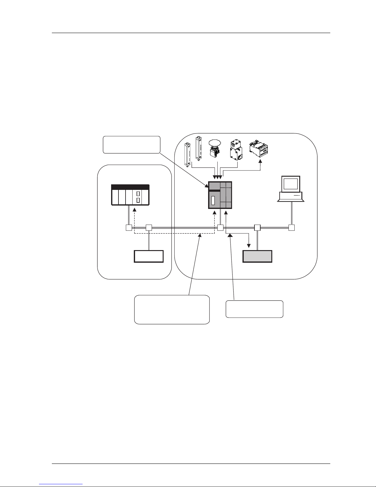
1-1 DeviceNet Safety System Overview
1-1-1 About DeviceNet Safety
DeviceNet is an open-field, multi-vendor, multi-bit network, which combines the controls in the machine and
line control levels with information. The DeviceNet Safety network adds safety functions to the conventional
standard DeviceNet communications protocol. The DeviceNet Safety concept has been approved by a thirdparty organization (TUV Rhineland).
Just as with DeviceNet, DeviceNet Safety-compliant devices from third-party vendors can be connected to a
DeviceNet Safety network. Also, DeviceNet-compliant devices and DeviceNet Safety-compliant devices can
be combined and connected on the same network.
By combining DeviceNet Safety-compliant products, a user can construct a safety control/network system
that meets the requirements for Safety Integrity Level (SIL) 3 according to IEC 61508 (Functional Safety of
Electrical/Electronic/Programmable Electronic Safety-related Systems) and the requirements for Safety Category 4 according to EN 954-1.
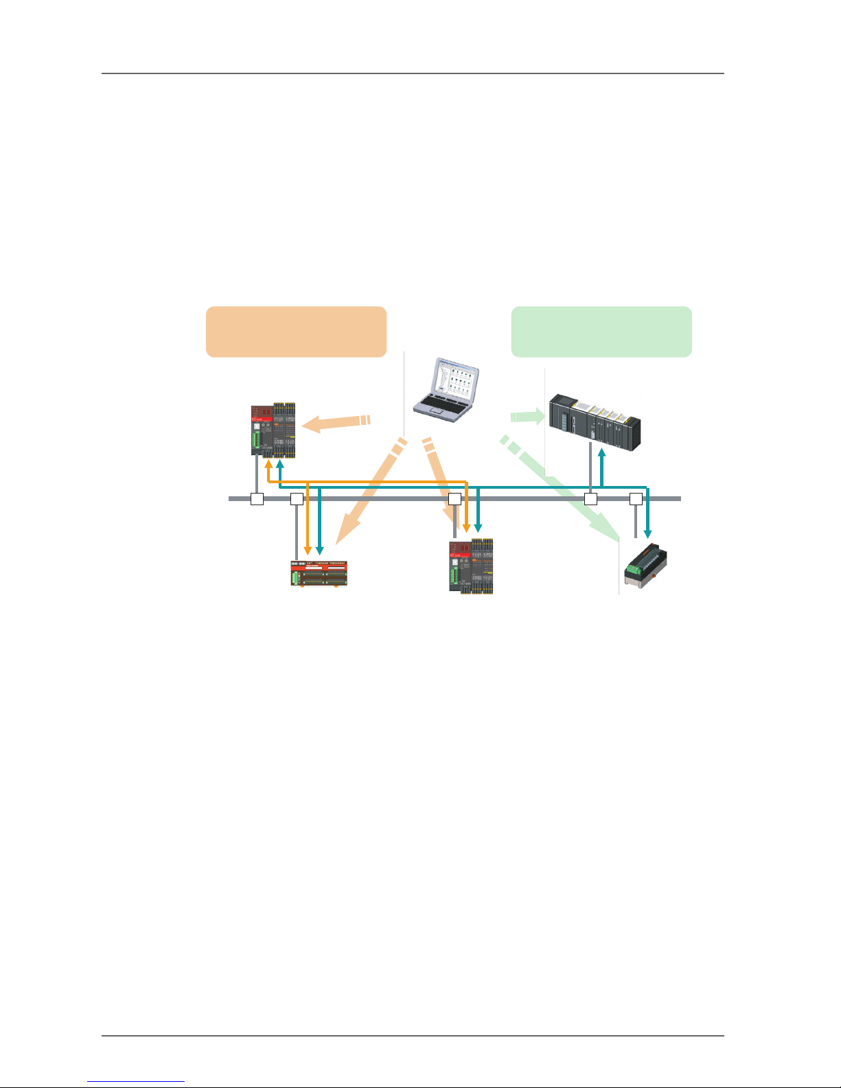
Standard communications
Safety Network Controller
-
Safety Master functions
-
Standard Slave functions
Standard PLC and Master
Safety I/O Terminal
-
Safety Slave functions
-
Standard Slave functions
Safety Network Controller
-
Safety Slave functions
-
Standard Slave functions
Standard Slave
Network Configurator
Safety
configuration
Standard
configuration
Safety communications
Safety Control performed by the
Safety Network Controller
-
Safety remote I/O communications
Standard Control and Monitoring b
y
the Standard PLC
-
Standard remote I/O communications
-
Ex
p
licit message communications
Page 19
1-2 Safety Network Controller Overview 17
1-2 Safety Network Controller Overview
1-2-1 About the NE1A Safety Network Controller
The NE1A Safety Network Controller (NE1A-SCPU01) provides various functions, such as safety logic operations, safety I/O control, and a DeviceNet Safety protocol. The NE1A-SCPU01 allows the user to construct a safety control/network system that meets the requirements for Safety Integrity Level (SIL) 3
according to IEC 61508 (Functional Safety of Electrical/Electronic/ Programmable Electronic Safety-related
Systems) and the requirements for Safety Category 4 according to EN 954-1.
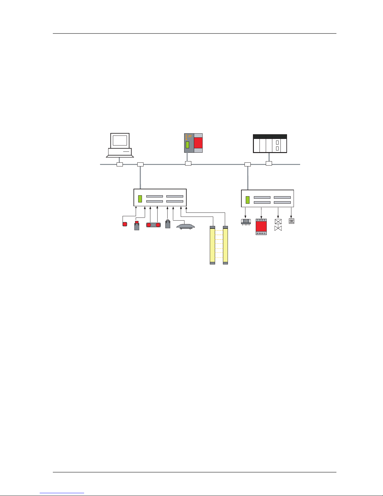
In the example system shown below, the safety control system implemented with the NE1A-SCPU01 and the
monitoring system implemented with the standard PLC are realized on the same network.
• As a Safety Logic Controller, the NE1A-SCPU01 executes safety logic operations and controls local I/O.
• As a Safety Master, the NE1A-SCPU01 controls the remote I/O of Safety Slaves.
• As a Standard Slave, the NE1A-SCPU01 communicates with the Standard Master.
1-2-2 Safety Network Controller Features
Safety Logic Operations
In addition to basic logic functions, such as AND and OR, the NE1A-SCPU01 also supports application function blocks, such as Emergency Stop Pushbutton Monitoring and Safety Gate Monitoring, that enable various
safety applications.
Local Safety I/O
• A total of 24 local safety I/O points are supported: 16 input terminals and 8 output terminals.
• Faults in external wiring can be detected.
• Dual Channel Mode can be set for pairs of related local inputs.
When Dual Channel Mode is set, the NE1A-SCPU01 can evaluate the input data patterns and the time
discrepancy between input signals.
• Dual Channel Mode can be set for pairs of related local outputs. When Dual Channel Mode is set, the
NE1A-SCPU01 can evaluate the output data patterns.
DeviceNet Safety Communications
• As a Safety Master, the NE1A-SCPU01 can perform safety I/O communications with up to 16 connections using up to 16 bytes per connection.
PLC
DeviceNet Standard Master
SNC
Network Configurator
Non-safety-related Control
Safety Logic Operations
and Safety I/O Control
DeviceNet
Standard Slave
The PLC system monitors the SNC
(i.e., the safety control system) using
DeviceNet I/O communications and
explicit messages.
The DeviceNet Safety
System controls remote I/O
DRT1-series
DeviceNet Safety Slave
Safety-related Control
Page 20

18 Section 1: Overview
• As a Safety Slave, the NE1A-SCPU01 can perform safety I/O communications with a maximum of four
connections using up to 16 bytes per connection.
DeviceNet Communications
As a Standard Slave, the NE1A-SCPU01 can perform standard I/O communications with one Standard Master for up to two connections using up to 16 bytes per connection.
Standalone Controller Mode
The NE1A-SCPU01 can be used as a Standalone Controller by disabling the NE1A-SCPU01's DeviceNet
communications.
Configuration with a Graphical Tool
• A graphical tool is provided for both network configuration and logic programming. It enables easy configuration and programming.
• A Logic Editor can be activated from the Network Configurator.
• Configuration data can be downloaded and uploaded, and devices can be monitored online via
DeviceNet, USB, or the peripheral interface of an OMRON PLC.
System Startup and Error Recovery Support
• Error information can be checked by using the error log function or the indicators on the front of the
NE1A-SCPU01.
• The NE1A-SCPU01's internal status information can be monitored from a standard PLC by allocating
the information in the Standard Master. In the same way, the information can be monitored from a safety
PLC by allocating the information in the Safety Master.
Access Control with a Password
• NE1A-SCPU01 configuration data is protected by a password.
• Network configuration files (project files) created with the Network Configurator are also password protected.
1-2-3 Standard Models
Model number Name Number of I/O points
Safety inputs Test outputs Safety outputs
NE1A-SCPU01 Safety Network Controller (NE1A-
SCPU01)
16 inputs 4 outputs 8 outputs
Page 21
1-3 Safety I/O Terminal Overview 19
1-3 Safety I/O Terminal Overview
1-3-1 About the DST1-series Safety I/O Terminals
The Safety I/O Terminals support the DeviceNet Safety protocol and provide various functions for the Safety
System. The Safety I/O Terminals allow the user to construct a safety control/network system that meets the
requirements for Safety Integrity Level (SIL) 3 according to IEC 61508 (Functional Safety of Electrical/Electronic/ Programmable Electronic Safety-related Systems) and the requirements for Safety Category 4 according to EN 954-1.
The DST1-series safety I/O data is transmitted through safety I/O communications conforming to the DeviceNet Safety Protocol, and the data processing is performed in the Safety Network Controller (NE1ASCPU01).
Also, the status of the safety I/O data can be monitored in a standard PLC in an existing DeviceNet network
using standard I/O communications or explicit message communications.
1-3-2 Safety I/O Terminal Features
Safety Inputs
• Semiconductor output devices such light curtains can be connected as well as contact output devices
such as emergency stop switches.
• Faults in external wiring can be detected.
• Input delays (ON delays and OFF delays) can be set.
• Pairs of related local inputs can be set to Dual Channel Mode in order to be compliant with the Category
4 standards.
When Dual Channel Mode is set, the input data patterns and the time discrepancy between input signals can be evaluated.
Test Outputs
• 4 independent test outputs are available to use.
• A disconnected external indicator lamp can be detected. (Can be set for the T3 Terminal only.)
• Test outputs can be used as power supply terminals to devices such as sensors.
• Test outputs can be used as the standard output terminals for monitor outputs.
Safety Outputs
• Semiconductor Outputs
• Pairs of related local outputs can be set to Dual Channel Mode in order to be compliant with the
Category 4 standards.
When Dual Channel Mode is set, the output data patterns can be evaluated.
• The rated output current is 0.5 A max. per output.
Network Configurator
DeviceNet
Emergency stop switch
Safety gate switch
Two-hand switch
Safety limit switch
Safety Ligh t Curtain
Safety relay
Enable switch
Safety Relay Unit
Valv e
Safety Network Controller
Contactor
DST1-series
Safety I/O Terminal
DST1-series
Safety I/O Terminal
Standard PLC
DeviceNet Master Unit
Page 22

20 Section 1: Overview
•Relay Outputs
• Pairs of related output terminals can be set to Dual Channel Mode in order to be compliant with the
Category 4 standards.
When Dual Channel Mode is set, the output data patterns can be evaluated.
• The rated output current is 2 A max. per output terminal.
• The safety relays can be replaced.
DeviceNet Safety Communications
As a Safety Slave, the Safety I/O Terminal can perform safety I/O communications with up to four connections.
DeviceNet Communications
As a Standard Slave, the Safety I/O Terminal can perform standard I/O communications with one Standard
Master with up to two connections.
System Startup and Error Recovery Support
• Error information can be checked by using the error log function or the indicators on the front of the
Safety I/O Terminal.
• The Safety I/O Terminal's safety I/O data and internal status information can be monitored from a Standard PLC by allocating the information in the standard Master. In the same way, the information can be
monitored from a safety PLC by allocating the information in the Safety Master.
Access Control with a Password
Safety I/O Terminal configuration data is protected by a password.
I/O Connector Connection/Disconnection
• The I/O Connector can be connected and disconnected.
• The I/O Connector is structured to prevent incorrect connection.
Cage Clamp Wiring
Cables can be wired without terminal screws.
Maintenance Functions
The Safety I/O Terminals are equipped with Maintenance Functions such as a contact operation counter, cumulative ON time monitor, and operating time monitor.
1-3-3 Standard Models
The following table shows the three models of DST1-series Safety I/O Terminals that are available: the Safety Input Terminal, Safety I/O Terminal (Semiconductor Output), and Safety Input/Output Terminal (Relay Output).
Model number Name Number of I/O points
Safety
inputs
Test
outputs
Safety outputs
Semiconductor
outputs
Relay outputs
DST1-ID12SL-1 Safety Input Terminal 12 inputs 4 outputs - DST1-MD16SL-1 Safety I/O Terminal
(Semiconductor Output)
8 inputs 4 outputs 8 outputs -
DST1-MRD08SL-1 Safety I/O Terminal
(Relay Output)
4 inputs 4 outputs - 4 outputs
Page 23
1-4 Network Configurator Overview 21
1-4 Network Configurator Overview
1-4-1 About the Network Configurator
The WS02-CFSC1-E Network Configurator is Support Software used to configure, set, and manage a DeviceNet Safety network with graphical window operations.
The Network Configurator can be used to configure a virtual DeviceNet Safety network (in the Network Configuration Window) and monitor the configuration and parameters of each safety device and standard device.
1-4-2 Network Configurator Features
Compliant with Standard and Safety DeviceNet Networks
The Network Configurator can configure and monitor DeviceNet Safety compliant devices as well as existing
standard DeviceNet devices. Consequently, the Network Configurator supports various system configurations, including standard systems, safety systems, and mixed systems containing both standard and safety
devices.
NE1A-SCPU01 Programming
The Network Configurator is equipped with a Programming Tool that is compatible with the NE1A-SCPU01's
safety logic programming. DeviceNet Safety applications can be created independently with the Network
Configurator.
Upward Compatibility with DeviceNet Configurator
All the functions of DeviceNet Configurator are supported. Also, all of the files created by the DeviceNet Configurator can be used as they are.
Page 24
22 Section 1: Overview
1-4-3 System Requirements
The following computer specifications are required in order to use the Network Configurator.
1-4-4 Standard Models
Item Specification
Computer IBM PC/AT or compatible computer with 300 MHz or faster processor
128 MB RAM min.
40 MB free hard disk space
Super VGA (800 x 600) or higher Display
CD-ROM drive or DVD drive
OS Windows
®
2000 or Windows® XP
COM Port One of the following COM Ports is required:
• USB Port: For an online connection via the NE1A-SCPU01's USB port (USB 1.1)
• DeviceNet Interface Card (3G8E2-DRM21-V1): For an online connection via DeviceNet
Model number Name Component Compatible
computer
OS
WS02-CFSC1-E Network
Configurator
Installation disk
(CD-ROM)
IBM PC/AT or
compatible
Windows
®
2000 or
Windows
®
XP
Page 25
1-5 Basic System Startup Procedure 23
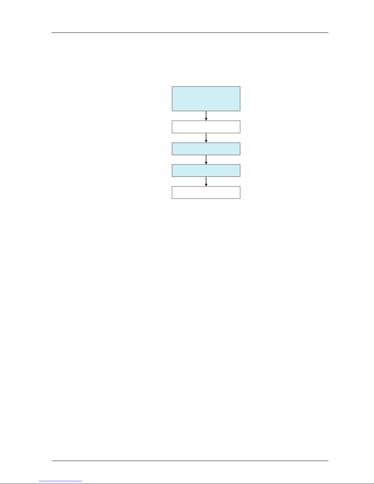
1-5 Basic System Startup Procedure
This manual introduces the basic steps that are needed to make the safety system operational, with particular
focus on the following steps.
– System Design and Programming
– Configuration
– Testing
1-5-1 System Design and Programming
In this step, the optimum safety system is determined by the following procedures:
(1) Based on the required safety system specifications, select and arrange the safety devices and deter-
mine the safety functions to be allocated to each device.
(2) Configure the network system as a virtual network in the Network Configurator.
• Register all of the devices. If the system is a mixed safety control and standard control system, register both the safety devices and standard devices.
• Set the parameters of all the devices.
• Check the percentage of the network bandwidth being used and review the parameters.
• Create the program for the NE1A-SCPU01.
• Verify the system reaction time of all the safety chains.
The network bandwidth usage and the system reaction time are affected by several factors, including the network configuration, NE1A-SCPU01 and Safety I/O Terminal parameter settings, and NE1A-SCPU01 program, so repeat the steps above to determine a system configuration which meets the users' requirements.
Please refer to the following sections for the operating instructions of the Network Configurator.
• Device Registration
• Refer to 2-4 Creating a Virtual Network (page 34).
• Editing Device Parameters
• Refer to 2-7 Device Parameters and Properties (page 41).
• Refer to Section 4: Editing Safety I/O Terminal Parameters (page 69).
• Refer to Section 5: Editing Safety Network Controller Parameters (page 79).
• Checking the Usage Rate of Network Bandwidth
• Refer to 3-2 Verifying the Network Bandwidth (page 59).
• Calculating the Reaction Time
• Refer to 3-3 Calculating and Verifying the Maximum Reaction Time (page 63).
IMPORTANT: Allocate a unique safety network number to each safety network or safety subnetwork.
1-5-2 Installation and Wiring
In this step, install and wire each device as shown below:
• Install all of the devices and set node addresses and baud rates.
• Connect to I/O devices.
• Wire the power supplies.
• Wire the DeviceNet.
1. System Design
&
Programming
2. Installation and Wiring
3. Configuration
4. User Test
5. System Operation
Page 26
24 Section 1: Overview
• Wire the USB.
Please refer to the following related manuals for details:
1-5-3 Configuration
In this step, transfer the parameters for each device created by the Network Configurator to the actual device
to make the system operative.
Use the Network Configurator to perform the following operations:
(1) Download
The parameters set in the Network Configurator's virtual network are transferred to the actual device
and stored in each device.
(2) Verification
Verify the safety device settings.
The user confirms that the parameters and safety signatures stored in each device are correct.
Please refer to the following sections for the operating instructions of the Network Configurator.
•Download
• Refer to 2-7 Device Parameters and Properties (page 41).
• Verification
• Refer to 2-8 Parameter Verification (page 45).
IMPORTANT: • After downloading the device parameters, verify the parameters to confirm that the param-
eters and the safety signature saved in the devices are correct.
• When selecting Open Only in the Open Type setting for the safety connection, check that
the Safety Master and Safety Slave are correctly configured.
1-5-4 User Test
In this step, the user himself confirms the program operation and performs functional tests.
Always perform the user test, because it is the user's responsibility to verify the system operation. The user
test verifies the correctness of all parameters downloaded to each safety device, as well as each device's
safety signature. To demonstrate that all parameters and safety signatures are correct after completing the
user test, perform a Configuration Lock operation on all of the safety devices.
Refer to 2-9 Configuration Lock (page 48) for details on performing a Configuration Lock from the Network
Configurator.
IMPORTANT: • After configuring all the devices, user testing must be performed to check if the configura-
tion data and device operation of each device are correct. User testing is performed to verify the safety signature for each device.
• The configuration must be locked after the user testing has completed.
Item Manual name Cat. No.
DeviceNet installation DeviceNet Operation Manual W267
NE1A-SCPU01 installation NE1A-SCPU01 Safety Network Controller Operation
Manual
Z906
DeviceNet Safety I/O Terminal installation DeviceNet Safety I/O Terminal Operation Manual Z904
Installation of other devices Operation manual for each device ?
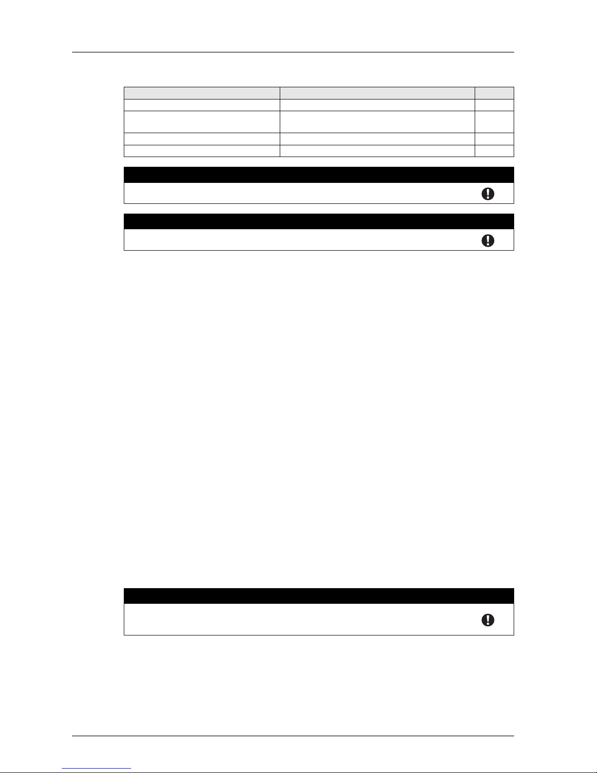
! WARNING
Safety functions may be impaired and serious injury may occasionally occur. Before connecting a device to the network, clear the previous configuration data.
! WARNING
Safety functions may be impaired and serious injury may occasionally occur. Before connecting a device to the network, set the appropriate node address and baud rate.
! WARNING
Safety functions may be impaired and serious injury may occasionally occur. Before operating the system, perform user testing to confirm that the configuration data of all the devices
is correct and that they are operating correctly.
Page 27

25
Section 2: Basic Operation of the Network Configurator
2-1 Network Configurator Startup and Main Window . . . . . . . . . . . . . . . . . . . . . . 27
2-1-1 Starting and Exiting the Network Configurator . . . . . . . . . . . . . . . . . . . 27
2-1-2 Checking the Version . . . . . . . . . . . . . . . . . . . . . . . . . . . . . . . 28
2-1-3 Main Window. . . . . . . . . . . . . . . . . . . . . . . . . . . . . . . . . . . . 28
2-2 Menu List . . . . . . . . . . . . . . . . . . . . . . . . . . . . . . . . . . . . . . . . . . . . 29
2-2-1 File Menu . . . . . . . . . . . . . . . . . . . . . . . . . . . . . . . . . . . . . 29
2-2-2 Edit Menu . . . . . . . . . . . . . . . . . . . . . . . . . . . . . . . . . . . . . 29
2-2-3 View Menu . . . . . . . . . . . . . . . . . . . . . . . . . . . . . . . . . . . . . 29
2-2-4 Network Menu . . . . . . . . . . . . . . . . . . . . . . . . . . . . . . . . . . . 29
2-2-5 Device Menu . . . . . . . . . . . . . . . . . . . . . . . . . . . . . . . . . . . . 30
2-2-6 EDS File Menu . . . . . . . . . . . . . . . . . . . . . . . . . . . . . . . . . . . 31
2-2-7 Tools Menu . . . . . . . . . . . . . . . . . . . . . . . . . . . . . . . . . . . . 31
2-2-8 Option Menu . . . . . . . . . . . . . . . . . . . . . . . . . . . . . . . . . . . . 31
2-2-9 Help Menu . . . . . . . . . . . . . . . . . . . . . . . . . . . . . . . . . . . . . 31
2-3 Connecting to the Network . . . . . . . . . . . . . . . . . . . . . . . . . . . . . . . . . .32
2-3-1 Network Connection via USB Port . . . . . . . . . . . . . . . . . . . . . . . . . 32
2-3-2 Network Connection via DeviceNet Interface Card . . . . . . . . . . . . . . . . 33
2-4 Creating a Virtual Network. . . . . . . . . . . . . . . . . . . . . . . . . . . . . . . . . . . 34
2-4-1 Creating a New Virtual Network . . . . . . . . . . . . . . . . . . . . . . . . . . 34
2-4-2 Network Numbers . . . . . . . . . . . . . . . . . . . . . . . . . . . . . . . . . 34
2-4-3 Adding Devices . . . . . . . . . . . . . . . . . . . . . . . . . . . . . . . . . . 35
2-4-4 Deleting Devices . . . . . . . . . . . . . . . . . . . . . . . . . . . . . . . . . . 36
2-4-5 Changing the Node Address . . . . . . . . . . . . . . . . . . . . . . . . . . . . 37
2-4-6 Changing Device Comments . . . . . . . . . . . . . . . . . . . . . . . . . . . 37
2-5 Saving and Reading Network Configuration Files . . . . . . . . . . . . . . . . . . . . . . 38
2-5-1 Password Protection of the Network Configuration File . . . . . . . . . . . . . . 38
2-5-2 Saving the Network Configuration File. . . . . . . . . . . . . . . . . . . . . . . 38
2-5-3 Reading a Network Configuration File . . . . . . . . . . . . . . . . . . . . . . . 39
2-5-4 Protect Mode . . . . . . . . . . . . . . . . . . . . . . . . . . . . . . . . . . . . 39
2-6 Device Password Protection . . . . . . . . . . . . . . . . . . . . . . . . . . . . . . . . .40
2-6-1 Setting a Device Password . . . . . . . . . . . . . . . . . . . . . . . . . . . . 40
2-6-2 Forgotten Device Passwords . . . . . . . . . . . . . . . . . . . . . . . . . . . 40
2-7 Device Parameters and Properties . . . . . . . . . . . . . . . . . . . . . . . . . . . . . . 41
2-7-1 Editing Device Parameters. . . . . . . . . . . . . . . . . . . . . . . . . . . . . 41
2-7-2 Uploading Device Parameters . . . . . . . . . . . . . . . . . . . . . . . . . . . 41
2-7-3 Downloading Device Parameters . . . . . . . . . . . . . . . . . . . . . . . . . 41
2-7-4 Device Properties . . . . . . . . . . . . . . . . . . . . . . . . . . . . . . . . . 43
2-8 Parameter Verification . . . . . . . . . . . . . . . . . . . . . . . . . . . . . . . . . . . . . 45
2-8-1 Device Parameter Verification . . . . . . . . . . . . . . . . . . . . . . . . . . . 45
2-9 Configuration Lock. . . . . . . . . . . . . . . . . . . . . . . . . . . . . . . . . . . . . . . 48
2-9-1 Locking the Device Configuration . . . . . . . . . . . . . . . . . . . . . . . . . 48
2-9-2 Unlocking the Device Configuration . . . . . . . . . . . . . . . . . . . . . . . . 48
Page 28

26 Section 2: Basic Operation of the Network Configurator
2-10 Device Reset and Status Change . . . . . . . . . . . . . . . . . . . . . . . . . . . . . . 49
2-10-1 Reset Types . . . . . . . . . . . . . . . . . . . . . . . . . . . . . . . . . . . 49
2-10-2 Resetting Devices . . . . . . . . . . . . . . . . . . . . . . . . . . . . . . . . 50
2-10-3 Reset Types and Device Status . . . . . . . . . . . . . . . . . . . . . . . . . 50
2-10-4 Changing Device Status . . . . . . . . . . . . . . . . . . . . . . . . . . . . . 51
Page 29
2-1 Network Configurator Startup and Main Window 27
2-1 Network Configurator Startup and Main Window
This section describes methods for starting and exiting the Network Configurator, describes how to check the
Network Configurator version and describes the Main Window.
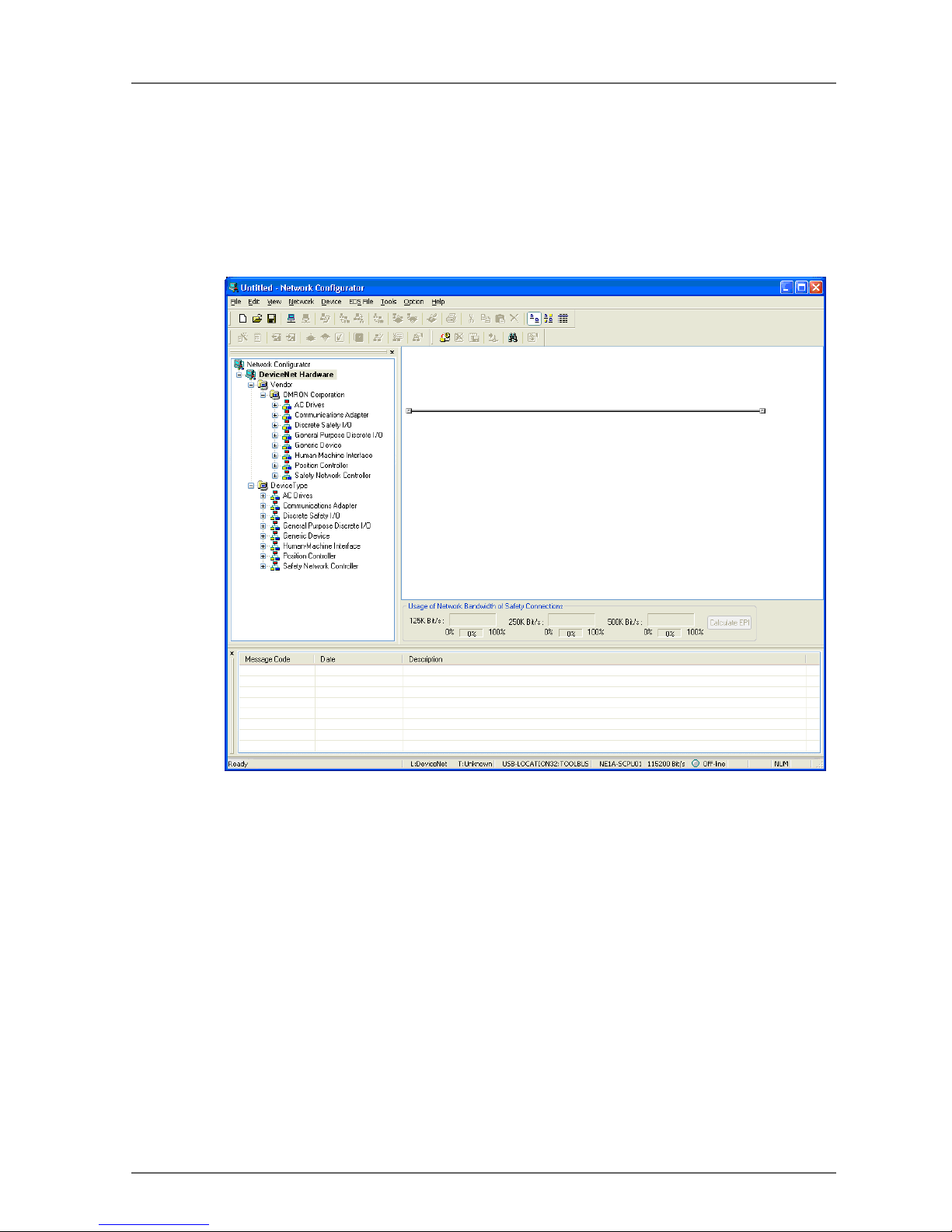
2-1-1 Starting and Exiting the Network Configurator
Starting
Select Program -OMRON Network Configurator for DeviceNet Safety - Network Configurator from the
Windows Start Menu (when using the default program folder name).
The Network Configurator will start, and the following window will be displayed.
Exiting
Select File -Exit in the Main Window.
The Network Configurator will close.
Page 30
28 Section 2: Basic Operation of the Network Configurator
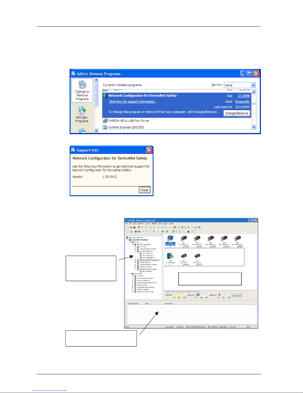
2-1-2 Checking the Version
The procedure to check the Network Configurator version is as follows:
1. Select the Control Panel from the Windows Start Menu.
2. Select the Add or Remove Programs (Windows XP) or Add/Remove Programs (Windows 2000).
3. Select the Network Configurator for DeviceNet Safety from the installed program list, and then refer
to the support information by following each display.
4. The version will be displayed as support information.
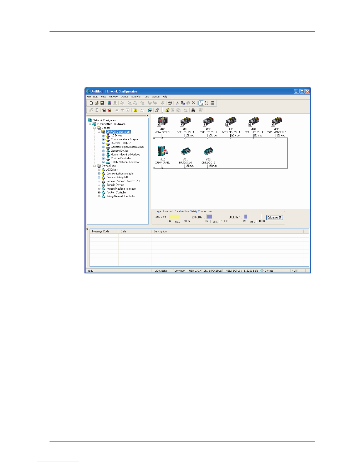
2-1-3 Main Window
The Main Window consists of the Hardware List, the Network Configuration Pane, and the Message Pane.
Hardware List:
Message Report Pane:
Network Configuration Pane:
Displays the virtual network.
Displays the devices that
can be added to the
network.
Displays information, such as
communications errors.
Page 31

2-2 Menu List 29
2-2 Menu List
This section describes the function of each menu command of the Network Configurator.
"Online" is the state in which the Network Configurator is connected to the network. "Offline" is the state in
which the Network Configurator is disconnected from the network.
2-2-1 File Menu
•
2-2-2 Edit Menu
•
2-2-3 View Menu
•
2-2-4 Network Menu
•
Submenu Description Offline Online
New Creates a new network configuration. O O
Open Opens an existing network configuration file. O O
Save Saves the current network configuration to a file. O O
Save As Names and saves the current network configuration. O O
External Data Export Exports in CSV format a file with the contents displayed
in the detailed display.
OO
Import Imports a network configuration file created in DeviceNet
Configurator version 1 or version 2.
OO
Change Password Changes the password of the network configuration file. O O
Report Creates a report on a specified device. O O
Print Prints the device parameters and I/O comment list. O O
Setup Printer Sets up the printer. O O
Exit Exits the Configurator. O O
O: Supported ×: Not supported
Submenu Description Offline Online
Cut Deletes selected devices and copies them to the clip-
board.
OO
Copy Copies selected devices to the clipboard. O O
Paste Pastes a device on the clipboard to the cursor position. O O
Delete Deletes selected devices. O O
Select All Selects all the devices. O O
Clear Message Report Clears a message in the Message Pane. O O
O: Supported ×: Not supported
Submenu Description Offline Online
Toolbar Displays or hides the toolbar. O O
Status Bar Displays or hides the status bar. O O
Message Report Displays or hides the Message Pane. O O
Large Icons Switches to network display. O O
Large Icons - Maintenance
Mode
Displays or hides maintenance information. O O
Details Switches to the detailed display. O O
Hardware List Displays or hides the Hardware List. O O
O: Supported ×: Not supported
Submenu Description Offline Online
Connect Connects the Network Configurator to the network. O ×
Disconnect Disconnects the Network Configurator from the network. × O
Change Connect Network
Port
Changes the destination network port. × O
Move Network Switches the network to connect. × O
O: Supported ×: Not supported
Page 32

30 Section 2: Basic Operation of the Network Configurator
2-2-5 Device Menu
•
Note: The Device Menu and Edit Menu can be partially displayed by right-clicking in the Network Configu-
ration Pane.
Wireless
Network
Move to Upper Network
Displays the network one layer above the current network in the wireless networks.
×O
Move to
Lower Network
Displays the network one layer below the current network
in the wireless networks.
×O
Upload Uploads all the device parameters in the network to the
Network Configurator.
×O
Download Downloads all the device parameters in the Network
Configurator to the devices in the network.
×O
Verify Structure Verifies the current network configuration in the Network
Configurator with the actual network configuration of the
destination online connection.
×O
Update Maintenance Information
Updates the maintenance information of each device to
the latest information.
×O
Check Connection Checks the consistency of all the connections. O O
Property Displays the network properties. The network name and
safety network number can be set.
OO
Submenu Description Offline Online
O: Supported ×: Not supported
Submenu Description Offline Online
Parameter Wizard Configures the device parameters in a wizard format.
This function is not supported by all devices.
OO
Edit Edits the device parameters. O O
Read Reads the parameters from the device parameter file. O O
Save As Saves the device parameters to a file. O O
Upload Uploads the device parameters from a device in the net-
work.
×O
Download Downloads the device parameters to a device in the net-
work.
×O
Verify Verifies the device and the device parameters in the net-
work.
×O
Lock Locks the configuration of a device in the network. × O
Unlock Unlocks the locked configuration of a device in the net-
work.
×O
Monitor Monitors the parameters and status of a device in the
network. Not all devices support this function.
×O
Reset Resets a device in the network. × O
Change Mode Changes the status of a device in the network. Not all de-
vices support this function.
×O
Change Password Changes the password of a device in the network. × O
Maintenance Information Displays the maintenance information of a device in the
network.
×O
Register to Another Device Registers a device to another device. O O
External
Data
Export Exports I/O comments or device parameters to another
file format. Not all devices support this function.
OO
Import Imports a device parameter file created with DeviceNet
Configurator (version 1 or version 2). Not all devices support this function.
OO
Change Node Address Changes a device node address. O O
Change Device Comment Changes a device name. O O
Edit I/O Comment Edits the I/O comment. O O
Property Displays the properties of a device. O O
O: Supported ×: Not supported
Page 33

2-2 Menu List 31
2-2-6 EDS File Menu
•
Note: The EDS File Menu can be displayed by right-clicking in the Hardware List Window.
2-2-7 Tools Menu
•
2-2-8 Option Menu
•
2-2-9 Help Menu
•
Submenu Description Offline Online
Install Installs an EDS file and adds a device to the Hardware
List.
OO
Create Creates a new EDS file and adds a device to the Hard-
ware List.
OO
Delete Deletes a device from the Hardware List. The installed
EDS file is also deleted.
OO
Save As Names and saves the EDS file of a device on the Hard-
ware List.
OO
Find Searches for a specified EDS file from the Hardware List. O O
Add to Network Adds a device on the Hardware List to the virtual net-
work.
OO
Property Displays the properties of an EDS file. O O
O: Supported ×: Not supported
Submenu Description Offline Online
Setup Parameters Sets parameters by using explicit message communica-
tions.
×O
Setup Node Address/Baud
Rate
Sets the node address and baud rate of a device in the
network.
×O
O: Supported ×: Not supported
Submenu Description Offline Online
Select Interface Selects an interface for the Network Configurator to use
for the network connection.
OO
Edit Configuration File Edits various configuration files. O O
Setup Monitor Refresh Tim-erSets the monitor refresh timer values (monitoring cycles
in device monitoring).
OO
Install Extend Module Installs an Expansion Module. O O
Install Interface Module Installs an Interface Module. O O
Parameter Auto Update
when Configuration
Changed
If this option is selected, the slave I/O size registered in
the Master will also be updated automatically when a
slave I/O size is changed. The default is OFF (do not update). Under normal conditions, leave this option OFF.
OO
O: Supported ×: Not supported
Submenu Description Offline Online
Topic Searches the help topics. O O
About Displays the version information of the Network Configu-
rator.
OO
Page 34

32 Section 2: Basic Operation of the Network Configurator
2-3 Connecting to the Network
The Network Configurator must be connected to the network to perform operations that are valid only when
online, such as obtaining the network configuration from an actual network or downloading the configured
device parameters to actual devices.
This section describes the procedure for connecting to the network via the USB port on the NE1A-SCPU01
and a DeviceNet Interface Card installed in a computer. Refer to the Appendix for other network connection
procedures.
2-3-1 Network Connection via USB Port
1. Turn ON the power supply to the NE1A-SCPU01 and connect it to a USB port on the computer.
2. Select Option - Select Interface - NE1A USB Port followed by the desired mode from the menu bar.
3. Select Network - Connect from the menu bar.
If an online connection is made normally, On-line will be displayed in the status bar at the bottom of the window.
Page 35

2-3 Connecting to the Network 33
2-3-2 Network Connection via DeviceNet Interface Card
1. Select Option - Select Interface - DeviceNet I/F.
2. Select Network - Connect.
The Select Interface Dialog Box will be displayed.
3. Select the interface card, and click the OK Button.
The Setup Interface Dialog Box will be displayed.
This window varies depending on the type of interface card. In this example, a DeviceNet PCMCIA Card
(3G8E2-DRM21-V1) is used. If you use another interface card, refer to the operation manual for the
card.
4. Set the MAC ID (node address) and baud rate, and click the OK Button.
The Select Connect Network Port Dialog Box will be displayed.
In the first network connection, a network search is performed automatically with this dialog box displayed. Wait until the search has been performed for all addresses. After the search, the networks that
can be connected will be displayed.
Automatic searching for networks will not be performed the second time or after.
5. Select the network to connect to, and click the OK Button.
If is online connection is made normally, On-line will be displayed in the status bar at the bottom of the
window.
Page 36

34 Section 2: Basic Operation of the Network Configurator
2-4 Creating a Virtual Network
To set device parameters and to program the NE1A-SCPU01, create a virtual network in the Network Configurator, set the device parameters in the virtual network, and then download them the parameters to the
actual devices.
This section describes how to create a virtual network.
2-4-1 Creating a New Virtual Network
When the Network Configurator is started, a new virtual network can be created.
Only one virtual network can be edited simultaneously. Use one of the following methods to create another
network.
(1) Select File - New from the menu bar.
(2) Click the New Button on the toolbar.
Note: When a new virtual network is created, the virtual network information that was displayed until then
will be deleted. If the previous virtual network information is required, save the data before creating a
new virtual network.
2-4-2 Network Numbers
The network number (i.e., the network address) is the number set for each network domain. All devices on
the same network must have the same network number.
The network number is set as a unique node identifier (UNID) in combination with the node address from the
Network Configurator and saved in the device. UNID is used to identify one device from all the network domains.
The Network Configurator automatically creates the network number based on the time and date when a new
network configuration file is created. Under normal conditions, the user does not have to consider this operation.
Note: When the parameters are downloaded to the devices, the network number is transferred with the pa-
rameters as the UNID and saved in the devices. Therefore, when using a device whose parameters
have already been downloaded to another domain, set the reset type to Return to the out-of-box configuration, and then emulate cycling power and perform a reset to clear the UNID.
Use the following procedure to set the network number.
(1) Select Network - Property from the menu bar.
(2) In the Network Number Field, select the Manual Option and enter the value.
IMPORTANT: Always allocate a unique network number when a network or subnetwork is established.
Page 37

2-4 Creating a Virtual Network 35
If the network number is not set correctly, a connection may be opened to a different device. A different network number must be set for each network domain, and the same network number must be set for all the
devices on the same domain.
2-4-3 Adding Devices
There are two ways to add a device to the virtual network.
(1) Adding from the Hardware List.
(2) Uploading the network configuration from the actual network.
Adding Devices from the Hardware List
There are two ways to add a device to the virtual network from the Hardware List.
(1) Double-click the selected device in the Hardware List.
(2) Select the device from the Hardware List and drag it to the Network Configuration Pane.
When a device has been registered, it will be displayed as follows:
Uploading the Network Configuration from the Actual Network (Network Upload)
The network configuration can be read from the actual network and to create the same configuration in the
virtual network. Connect the Network Configurator to the network, and then upload the network configuration
using any of the following methods.
(1) Select Network - Upload from the menu bar.
(2) Click Upload from Network on the toolbar. Uploading will start, and the detected devices will be dis-
played sequentially.
Page 38

36 Section 2: Basic Operation of the Network Configurator
(3) Right-click without selecting any device in the Network Configuration Pane and select Upload.
If there is another device that must be added after the upload has completed, add the device following the
same procedure as in Adding Devices from the Hardware List, above.
IMPORTANT: When the CS/CJ-series DeviceNet Unit exists in the network, disable the master function-
ality of the CS/CJ-series DeviceNet Unit, and then do the upload. If the master functionality
is enabled, uploading the device parameters may fail.
Note: – When a network is uploaded, the virtual network information that was displayed until then will be
deleted. If the previous virtual network information is required, save the data before the network upload.
– When a network in which devices already have a set network number is uploaded, the value that is
already set in the devices is used for the network number.
2-4-4 Deleting Devices
There are three ways to delete a device from a virtual network.
(1) Select a device, and then select Edit - Delete from the menu bar.
(2) Select a device, and then click the Delete Button on the toolbar.
(3) Select a device, and then right-click the selected device and select Delete.
A confirmation dialog box will be displayed before the deletion. Click the Delete Button to delete the device.
Page 39

2-4 Creating a Virtual Network 37
2-4-5 Changing the Node Address
When a device is added from the Device List, an unused node address from 0 to 63 is automatically allocated
sequentially in the order the device is added.
There are two ways to change the allocated node address.
(1) Select a device, and select Device - Change Node Address from the menu bar.
(2) Select a device, and then right-click the device and select Change Node Address.
The following dialog box will be displayed. Change the node address and click the OK Button.
2-4-6 Changing Device Comments
When a device is added from the Device List, the displayed comment is the device type. Device comments
can be set in the following two ways.
(1) Select a device, and then select Device - Change Device Comment from the menu bar.
(2) Select a device, and then right-click the device and select Change Device Comment.
The following dialog box will be displayed. Enter the device name and click the OK Button.
Page 40

38 Section 2: Basic Operation of the Network Configurator
2-5 Saving and Reading Network Configuration Files
The created network configuration of the virtual network can be saved in a file. Also, you can open the saved
file, modify it, or download it to the devices by connecting to the network.
2-5-1 Password Protection of the Network Configuration File
A password can be set for the network configuration file. The set password is encrypted and saved in the file.
By setting the password for the network configuration file, the file is protected from unintended or unauthorized access.
The network configuration file password must be entered when the following operations are performed in the
Network Configurator:
• Saving the network configuration file
• Reading the network configuration file
• Changing the network configuration file password
The passwords must match to save the file. If the password does not match when opening a file, Protect
Mode is started. In Protect Mode, some Network Configurator operations are restricted.
The password for the network configuration file is set when the file is saved for the first time. The password
must be from 6 to 16 alphanumeric characters. If you do not want to set a password, enter nothing and click
the OK Button.
To change the password for a network configuration file, select File - Change Password from the menu bar.
After changing the password, however, the file and the password must be saved.
IMPORTANT: • For security purposes, it is recommended to set a password for network for network con-
figuration files.
• Do not forget the set password. You cannot open a network configuration file if the password is forgotten.
2-5-2 Saving the Network Configuration File
The network configuration can be saved using either of the following methods.
(1) Select File - Save or File - Save As from the menu bar.
(2) Click the Save Button on the toolbar.
Either way, the standard Windows dialog box for saving will be displayed. Select the saving location, name
the file, and then click the Save Button.
When saving the file for the first time, the Assign Password Dialog Box will be displayed. Enter the password
to set for the network configuration file.
When saving the second time or after, the Password Confirmation Dialog Box will be displayed. Enter the
password set when the network configuration file was initially saved.
When saving has completed successfully, the following message will be displayed in the Message Pane:
Page 41

2-5 Saving and Reading Network Configuration Files 39
2-5-3 Reading a Network Configuration File
The saved network configuration file can be read for use by the Network Configurator using either of the following methods.
(1) Select File - Open from the menu bar.
(2) Click the Open Button on the toolbar.
Either way, the standard Windows Open File Dialog Box will be displayed. Select the file to open, and click
the Open Button.
Next, the Check Password Dialog Box will be displayed. Enter the password set when the network configu-
ration file was saved.
When reading has completed successfully, the following message will be displayed in the Message Pane:
Note: If the password does not match, the Network Configurator will open the file in Protect Mode. In Protect
Mode, operations such as saving the file, downloading parameters, and changing device status are
prohibited. Refer to 2-5-4 Protect Mode (page 39) for details.
2-5-4 Protect Mode
If the password does not match when opening the network configuration file, the Network Configurator will
open the file in Protect Mode.
If the password does not match, the following message will be displayed in a dialog box and the Message
Pane.
The following operations cannot be performed in Protect Mode.
• Saving a network configuration file
• Changing the password for the network configuration file
• Downloading the network configuration to devices in the network
• Downloading parameters to devices in the network
• Resetting devices in the network
• Changing passwords for devices in the network
• Sending explicit message requests to devices in the network
• Setting node addresses for devices in the network
• Setting the baud rate for devices in the network
Page 42

40 Section 2: Basic Operation of the Network Configurator
2-6 Device Password Protection
A safety device can save a password internally. Setting the password in the device prevents an unauthorized
person from changing the safety device parameters and status.
2-6-1 Setting a Device Password
Entering a device password is required when the following operations are performed on the Network Configurator. If the password does not match, the operations cannot be performed.
• Network downloading
• Parameter downloading
• Configuration locking
• Releasing a configuration lock
• Resetting
• Changing status
• Changing the password
A password is set for each device using either of the following methods. This function can be used only when
the Network Configurator is online.
(1) Select a device, and then select Device - Change Password from the menu bar.
(2) Select a device, and then right-click the device and select Change Password.
The Change Password Dialog Box will be displayed as shown in the following figure. Enter the current pass-
word and a new password, and click the OK Button. A password can contain from 6 to 16 alphanumeric characters.
Device passwords are not stored in the Network Configuration File. There is no password in the default settings. If the device is reset by setting the Reset Type to Return to the out-of-box configuration, and then em-
ulate cycling power, it will return to the no-password setting. To reset the device, however, entering the
current password is required. Therefore, do not forget the device password.
IMPORTANT: For security purposes, it is recommended to set passwords for devices.
Note: If you set the same password for multiple devices and perform an operation that requires entering a
password, entering the password once can be treated as entering the password for all the devices.
Select the Use this password for all device check box in the Password Input Dialog Box.
2-6-2 Forgotten Device Passwords
If you forget a device password, contact your OMRON Support Center. If you enter the recovery key obtained
from the Support Center in the Password Recovery Tool installed in the Network Configurator, you can return
the device to the no-password setting.
To obtain the recovery key, the following information is required. Use the Password Recovery Tool to obtain
the information from the device. For details, refer to Appendix 5 Using the Password Recovery Tool.
• Vendor ID
• Serial number
• Counter information
Page 43

2-7 Device Parameters and Properties 41
2-7 Device Parameters and Properties
Registered device parameters can be edited on the virtual network without restrictions. Also, for parameters
saved as a network configuration file, you can open the file later and download to a device or make modifications.
2-7-1 Editing Device Parameters
Device parameters can be edited using any of the following methods.
(1) Double click a device icon.
(2) Select a device, and then select Device - Parameter - Edit from the menu bar.
(3) Select a device, and then click the Edit Parameter Button on the toolbar.
(4) Select a device, and then right-click the device and select Parameter - Edit.
The edit window for device parameters varies depending on the device.
Refer to Section 4 (page 69) for editing device parameters of DST1-series Safety I/O Terminals.
Refer to Section 5 (page 79) for editing device parameters of the NE1A-SCPU01.
2-7-2 Uploading Device Parameters
Parameters of all the devices in the network can be uploaded from the network. Any of the following methods
enables uploading parameters from one or more selected devices. This function is enabled only when the
Network Configurator is online.
(1) Select one or more devices, and then select Device - Parameter - Upload from the menu bar.
(2) Select one or more devices, and then click the Upload from Device Button on the toolbar.
(3) Select one or more devices, and then, right-click each device and select Parameter - Upload.
IMPORTANT: When the CS/CJ-series DeviceNet Unit exists in the network, disable the master function-
ality of the CS/CJ-series DeviceNet Unit, and then do the upload. If the master functionality
is enabled, uploading the device parameters may fail.
Note: To upload the network configuration, refer to Uploading the Network Configuration from the Actual
Network (Network Upload) in 2-4-3 Adding Devices (page 35).
2-7-3 Downloading Device Parameters
There are two ways to download parameters to a device: downloading to the selected devices and downloading sequentially to all the devices in the network. Either way is acceptable. Make sure, however, to download parameters to all the devices.
This function is enabled only when the Network Configurator is online. Downloading parameters also requires entering the device passwords.
Downloading Parameters to a Selected Device
You can download parameters to selected devices using any of the following methods.
(1) Select one or more devices, and then select Device - Parameter - Download from the menu bar.
(2) Select a device, and then click the Download to Device Button on the toolbar.
(3) Select one or more devices, and then right-click each device and select Parameter - Download.
Next, the password input window for the device will be displayed. Enter the password for the selected devices
and click the OK Button.
When selecting multiple devices and setting the same device password for all the devices, select the Use
this password for all device check box in the following dialog box, and then entering passwords will no longer
be necessary for each device.
Downloading Parameters to All Devices in the Network (Network Download)
You can download parameters to all the devices in the network using any of the following methods.
Page 44

42 Section 2: Basic Operation of the Network Configurator
(1) Select Network - Download from the menu bar.
(2) Click the Download to Network Button on the toolbar.
(3) In the Network Configuration Pane, right-click without selecting any device and select Download.
The password input window of the devices will be displayed. As described in Downloading Parameters to a
Selected Device, enter the password for the selected devices and then click the OK Button.
Errors while Downloading
When an error occurs while downloading to multiple devices sequentially, the following dialog box will be displayed.
Downloading will continue to the next device if 15 seconds passes and neither button is clicked. If you want
to perform the next download immediately, however, click the Continue Button.
If you click the Abort Button, the download process will be cancelled (and consequently, the parameters will
not be downloaded to the subsequent devices).
The error that occurred will be listed at the end of processing and displayed in the Message Pane.
Page 45

2-7 Device Parameters and Properties 43
2-7-4 Device Properties
The device information, types of safety I/O and standard I/O, and safety signatures can be checked in the
Device Property Dialog Box.
The Device Property Dialog Box can be displayed using any of the following methods.
(1) Select a device, and then select Device - Property from the menu bar.
(2) Select a device, and the click the Device Property Button on the toolbar.
(3) Select a device, and then right-click the device and select Property.
General Tab Page
In this tab page, you can check the device information and change the device icon displayed in the Network
Configuration Pane.
Safety I/O Information Tab Page
In this tab page, you can check the safety I/O classification information of a device.
Page 46

44 Section 2: Basic Operation of the Network Configurator
I/O Information Tab Page
In this tab page, you can check the standard I/O classification information of a device.
Signature Tab Page
In this tab page, you can check the safety signature that the Network Configurator generated and the one
that the actual device has.
Page 47

2-8 Parameter Verification 45
2-8 Parameter Verification
After downloading the parameters to a device, the user must perform parameter verification to check whether
the parameters entered by the user were correctly downloaded to the device. The user must perform this
verification for safety devices.
2-8-1 Device Parameter Verification
Verify the parameters using any of the following methods after downloading the parameters to devices. This
function is enabled only when the Network Configurator is online.
(1) Select a device, and then select Device - Parameter - Verify from the menu bar.
(2) Select a device, and then click the Verify Parameter Button on the toolbar.
(3) Select a device, and then right-click the device and select Parameter - Verify.
The device parameters will be uploaded.
First, the Network Configurator itself checks if the uploaded parameters are different from the parameters in
the virtual network. If there are no differences, the following dialog box will be displayed.
If you click the OK Button, the uploaded parameters will be displayed.
Page 48

46 Section 2: Basic Operation of the Network Configurator
The user must check whether all the displayed parameters match the input values. If the device is the NE1ASCPU01, the Logic Program will also be displayed as in the following window. Check whether the Logic Program matches.
Note: The displayed parameters and logic can also be printed. To print, click the Print Button at the upper
left of the window.
After completing the verification, click the Close Button in the upper left to close the window.
The following window will be displayed.
If the parameters match, click the Yes Button.
After the verification has been completed, the safety symbol attached to the device icon in
the virtual network will turn green, which indicates that verification is done.
IMPORTANT: After downloading the configuration data, verify the parameters and
check whether the parameters saved in the device and the safety signature are correct.
Note: – After verifying the parameters of all the devices, make sure to save the network configuration file.
– The Verified configuration parameter symbol ensures that the device parameters in the network
configuration file are correct. This information is saved in the network configuration file, but not in
the device itself. Therefore, the Verified configuration parameter symbol will not be attached even
though the network configuration is obtained by network upload from a device that has been already
verified.
– If you edit parameters that have been verified, the Verified configuration parameter symbol will dis-
appear. The device parameters must be verified again.
Page 49

2-8 Parameter Verification 47
Parameter Mismatch
When the Network Configurator detects a mismatch in parameter verification, the parameter with the mismatch will be displayed with the safety signature in the window as in the following example.
Check the parameter values and perform the download again.
Page 50

48 Section 2: Basic Operation of the Network Configurator
2-9 Configuration Lock
Perform user testing after verifying the device parameters. Checking all the operations of the device using
user testing indicates that the device parameters have been verified by the user.
The configuration lock symbol indicates that the user test has completed.
2-9-1 Locking the Device Configuration
After the user testing, lock the configuration using either of the following methods. This function is enabled
only when the Network Configurator is online. Also, to lock the configuration, verification of the device must
have been completed already.
(1) Select one or more devices, and then select Device - Parameter - Lock from the menu bar.
(2) Select one or more devices, and then click each device and select Parameter - Lock.
Next, the password input window for the device will be displayed. Enter the password of the selected devices
and click the OK Button.
When selecting multiple devices and setting the same device password for all the devices, select the Use
this password for all device check box in the following dialog box, and then entering passwords will no longer
be necessary for each device.
After the configuration lock has completed, the safety symbol attached to the device icon in
the virtual network will change to a symbol of a lock, which indicates that the configuration
lock has completed.
IMPORTANT: Operation of the device must be tested before lock the configuration.
Note: – After performing a configuration lock for all the devices, make sure to save the net-
work configuration file.
– The symbol that indicates that the configuration lock has been done ensures that the device has
been tested. This information is saved in the device itself as well as in the network configuration file.
– Once the configuration lock has been performed, you cannot download the parameters to the de-
vice. To change the parameters, release the configuration lock.
– When verified device parameters are edited, the Verified configuration parameter symbol will dis-
appear. The device parameters must be verified again.
2-9-2 Unlocking the Device Configuration
The configuration must be unlocked to change device parameters for which a configuration lock has been
performed. Unlock the configuration for the selected devices using any of the following methods. This function is enabled only when the Network Configurator is online.
(1) Select one or more devices, and then select Device - Parameter - Unlock from the menu bar.
(2) Select one or more devices, and then right-click each device and select Parameter - Unlock.
Next, the password input window for the device will be displayed. As in 2-9-1 Locking the Device Configura-
tion (page 48), enter the password for the selected devices and click the OK Button.
When the configuration unlock has completed, the safety symbol attached to the device
icon in the virtual network will return to the Verified configuration parameter symbol.
Note: When changing the device parameters after a configuration unlock, lock the config-
uration after verifying the parameters again.
Page 51

2-10 Device Reset and Status Change 49
2-10 Device Reset and Status Change
This section describes how to reset and change the status of safety devices.
For some device types, status changes may not be supported.
2-10-1 Reset Types
There are three ways to reset a safety device.
The safety device stores the following information in the nonvolatile memory of the device:
The information above is stored in the nonvolatile memory of the device, and so it is not cleared by cycling
the power source once it is set. To clear the information (to return to the default settings), select Return to
the out-of-box configuration, and then emulate cycling power or Return to the out-of-box configuration except
to preserve the following parameters, and then emulate cycling power.
Reset type Description
Emulate cycling power. Resets in the same way as cycling the power.
Return to the out-of-box configuration, and
then emulate cycling power.
Returns the information stored in the device nonvolatile memory
to the default settings and restarts.
Return information except for specified
parameters to the out-of-box configuration, and then emulate cycling power.
Returns all information stored in the device nonvolatile memory
other than specified data to the default settings, and then restarts.
Type Default setting Setting timing Description
Device parameter Not configured Parameter down-
load
Parameters and programs set by the user
Node address (software setting)
63 Node address
change
Node address at startup with software setting enabled
Baud rate (software
setting)
125 Kbit/s Baud rate change Baud rate at startup with software setting
enabled (NE1A-SCPU01 only)
TUNID
(Target Unique
Node Identifier)
Not set First parameter
download
The identifier of the local node in the Safe-
ty Network as well as the combined values
of the network number and node address
Password No password Password change Password that a device has
CFUNID
(Configuration Own-
ing UNID)
Not set First parameter
download
UNID of the configuration source
OCPUNID
(Output Connection
Point Owning UNID)
Not set Start of first safety
communi- cations
UNID of the Safety Master that opens a
safety output connection.
! WARNING
Failure to clear the previous configuration data before connecting the device to the network
may result in loss of safety functions, personal injury, or death.
Page 52

50 Section 2: Basic Operation of the Network Configurator
2-10-2 Resetting Devices
Reset devices using either of the following methods. This function is enabled only when the Network Configurator is online.
(1) Select one or more devices, and then select Device - Reset from the menu bar.
(2) Select one or more devices, and then right-click each device and select Reset.
The reset window of the devices will be displayed as shown in the following example. Enter a reset type and
the password and then click the OK Button.
For example, to keep the current password setting for multiples devices with the same password but return
other information to the default, specify the setting as follows:
2-10-3 Reset Types and Device Status
Resetting may not be supported for some types of reset and device status.
Reset type Device status
Safety connection being established and
configuration
locked.
Safety connection being established and
configuration
locked.
Safety connection not established and
configuration
locked.
Safety connection not established and
configuration
locked.
Emulate cycling power Unable to reset. Unable to reset. Able to reset. Able to reset.
Return to the out-of-box con-
figuration, and then emulate
cycling power.
Unable to reset. Unable to reset. Unable to reset. Able to reset.
Return information except for
specified parameters to the
out-of-box configuration, and
then emulate cycling power.
Unable to reset. Unable to reset. Unable to reset. Able to reset.
Page 53

2-10 Device Reset and Status Change 51
2-10-4 Changing Device Status
Changing the device status is not supported by all devices.
The NE1A-SCPU01 can switch between IDLE mode and RUN mode. For details on NE1A-SCPU01 modes,
refer to the Safety Network Controller Operation Manual (Z906).
For DST1-series Safety I/O Terminals, there is no need to change modes.
Change the device mode using either of the following methods. This function is enabled only when the Net-
work Configurator is online.
(1) Select a device, and then select Device - Change Mode followed by the desired mode.
(2) Select a device, and then right-click the device and select Change Mode followed by the desired mode.
Next, the password input window for the device will be displayed. Enter the password for the selected devices
and click the OK Button.
Page 54

52 Section 2: Basic Operation of the Network Configurator
Page 55

53
Section 3: Constructing a Safety Network
3-1 Applications . . . . . . . . . . . . . . . . . . . . . . . . . . . . . . . . . . . . . . . . . . 54
3-1-1 Establishing a New Safety Network . . . . . . . . . . . . . . . . . . . . . . . . 54
3-1-2 Changing an Established Safety Network . . . . . . . . . . . . . . . . . . . . . 56
3-2 Verifying the Network Bandwidth . . . . . . . . . . . . . . . . . . . . . . . . . . . . . . . 59
3-2-1 Checking the Network Bandwidth Used for Safety I/O Communications . . . . . 59
3-2-2 Allocating Network Bandwidth . . . . . . . . . . . . . . . . . . . . . . . . . . . 60
3-2-3 Example of EPI Calculation . . . . . . . . . . . . . . . . . . . . . . . . . . . . 61
3-3 Calculating and Verifying the Maximum Reaction Time. . . . . . . . . . . . . . . . . . . 63
3-3-1 Concept of Reaction Time . . . . . . . . . . . . . . . . . . . . . . . . . . . . . 63
3-3-2 Calculating the Maximum Reaction Time . . . . . . . . . . . . . . . . . . . . . 64
3-3-3 Verifying the Maximum Reaction Time . . . . . . . . . . . . . . . . . . . . . . 67
Page 56

54 Section 3: Constructing a Safety Network
3-1 Applications
This section describes how to construct a DeviceNet Safety Network in the following two cases.
(1) Establishing a new Safety Network
(2) Changing an established Safety Network
3-1-1 Establishing a New Safety Network
This section describes the procedure for establishing a system by designing a new Safety Network using the
Network Configurator and then downloading the parameters to the network devices.
System Design and Programming
1. Starting the Network Configurator
Start the Network Configurator.
Refer to 2-1-1 Starting and Exiting the Network Configurator (page 27).
2. Creating the Virtual Network
Create the virtual network by adding a device from the Hardware List. If the user is to specify the net-
work number, set the network number as well.
Refer to 2-4 Creating a Virtual Network (page 34).
3. Editing and Programming Device Parameters
Set the parameters of the DST1-series I/O Terminals configured in the virtual network.
Refer to Section 4: Editing Safety I/O Terminal Parameters (page 69) and to the DST1 Series I/O Termi-
nal Operation Manual (Z904).
Set the parameters of the NE1A-SCPU01 configured in the virtual network.
Refer to Section 5: Editing Safety Network Controller Parameters (page 79) and to the Safety Network
Controller Operation Manual (Z906).
Program the NE1A-SCPU01 configured in the virtual network.
Refer to Section 6: Programming the Safety Network Controller (page 97) and to the Safety Network
Controller Operation Manual (Z906).
4. Verifying the Network Bandwidth to Use
Confirm that the bandwidth used in the safety I/O communications does not exceed the acceptable
bandwidth in the network. If exceeded, re-examine the procedure from network configuration in step 2.
Refer to 3-2 Verifying the Network Bandwidth (page 59).
5. Calculating and Verifying the Maximum Reaction Time
Calculate the maximum reaction time of all the safety chains and check if the requirement specifications
are met. If the requirement specifications are not met, re-examine the procedure from network configuration in step 2.
Refer to 3-3 Calculating and Verifying the Maximum Reaction Time (page 63).
6. Saving the Network Configuration File
Save the network configuration file with the completed design.
Refer to 2-5-2 Saving the Network Configuration File (page 38).
7. Exiting the Network Configurator
Exit the Network Configurator.
The following operations are performed by connecting the Network Configurator to the network after the
network installation and wiring.
IMPORTANT: Allocate a unique safety network number to each safety network or safety subnetwork.
Configuration
8. Starting the Network Configurator and Connecting to the Network
Start the Network Configurator and connect it to the network via the USB port on the NE1A-SCPU01 or
a DeviceNet Interface Card.
Refer to 2-3 Connecting to the Network (page 32).
9. Reading the Network Configuration File
Read the saved network configuration file with the completed design.
Refer to 2-5-3 Reading a Network Configuration File (page 39).
10. Resetting a Device
When changing the configuration because of user testing results or when downloading the parameters
again, it is necessary to clear the previous configuration before downloading the new parameters.
Page 57

3-1 Applications 55
Reset the device by setting the reset type to Return to the out-of-box configuration, and then emulate
cycling power.
Refer to 3-1-2 Changing an Established Safety Network (page 56).
11. Downloading Device Parameters
Download the parameters to all the devices.
Refer to 2-7-3 Downloading Device Parameters (page 41).
12. Confirming the Downloaded Device Parameters and Safety Signatures
Verify the parameters for all the devices and check if the device parameters and program that the user
input have been correctly downloaded and saved in the devices.
Refer to 2-8 Parameter Verification (page 45).
13. Saving the Network Configuration File
Save the network configuration file in which parameter verification of all the devices has been com-
pleted.
Refer to 2-5-2 Saving the Network Configuration File (page 38).
14. Exiting the Network Configurator
Exit the Network Configurator.
IMPORTANT: • After downloading the device parameters, verify the parameters to confirm that the param-
eters and the safety signature saved in the devices are correct.
• When selecting Open Only in the Open Type setting for the safety connection, check that
the Safety Master and Safety Slave are correctly configured.
User Testing
15. User Testing
The user himself must verify device parameters and operation to confirm that safety system require-
ment specifications are met.
16. Starting the Network Configurator and Connecting to the Network
Start the Network Configurator and connect it to the network via the USB port on the NE1A-SCPU01 or
a DeviceNet Interface Card.
Refer to 2-3 Connecting to the Network (page 32).
17. Reading the Network Configuration File
Read the saved network configuration file with parameters that are already verified.
Refer to 2-5-3 Reading a Network Configuration File (page 39).
18. Configuration Lock
Lock the configuration of all the devices to indicate that they have been verified as well as to prevent
parameters from being mistakenly rewritten.
Refer to 2-9-1 Locking the Device Configuration (page 48).
19. Saving the Network Configuration File
Save the network configuration file of the virtual network in which the configuration is locked.
Refer to 2-5-2 Saving the Network Configuration File (page 38).
20. Exiting the Network Configurator
Exit the Network Configurator.
IMPORTANT: • After configuring all the devices, user testing must be performed to check if the configura-
tion data and device operation of each device are correct. User testing is performed to verify the safety signature for each device.
• The configuration must be locked after the user testing has completed.
Running the System
21. Running the System
Run the system.
! WARNING
Safety functions may be impaired and serious injury may occasionally occur. Before operating the system, perform user testing to confirm that the configuration data of all the devices
is correct and that they are operating correctly.
Page 58

56 Section 3: Constructing a Safety Network
3-1-2 Changing an Established Safety Network
This section describes procedure to change the Safety Network after the system is running.
Changing the System
1. Stopping the System
Turn OFF the power supplies to moving parts, such as motors, and stop the system. Continue supplying
power to the network and the NE1A-SCPU01.
2. Starting the Network Configurator and Connecting to the Network
Start the Network Configurator and connect it to the network via the USB port on the NE1A-SCPU01 or
a DeviceNet Interface Card.
Refer to 2-1-1 Starting and Exiting the Network Configurator (page 27) and 2-3 Connecting to the Net-
work (page 32).
3. Uploading the Network Configuration
Upload the network to obtain the current network configuration.
Refer to 2-4 Creating a Virtual Network (page 34).
4. Unlocking the Configurations
Unlock the configurations of all the devices to enable changing the network configuration.
Refer to 2-9-2 Unlocking the Device Configuration (page 48).
5. Resetting a Device
Before changing device parameters and node address, clear the configuration of the device. Reset the
device by setting the reset type to Return to the out-of-box configuration, and then emulate cycling
power.
6. Exiting the Network Configurator
Exit the Network Configurator.
7. Changing the System
Change the network, wiring, and node addresses and add or delete devices according to the specified
system changes. Safety devices that are being newly added must be configured in advance.
Note: There is no need to use the saved network configuration file, because the purpose of this procedure
is to unlock the device configurations and reset devices to the default configurations.
Redesigning the System
8. Starting the Network Configurator
Start the Network Configurator to redesign the network.
9. Reading the Network Configuration File
Read the saved network configuration file with a locked configuration.
Refer to 2-5-3 Reading a Network Configuration File (page 39).
10. Changing the Virtual Network
Add or delete the devices and change the node addresses according to specified changes.
Refer to 2-4 Creating a Virtual Network (page 34).
11. Changing the Device Parameters and Program
Set and change the parameters of the DST1-series I/O Terminals configured in the virtual network
according to specified changes.
Refer to Section 4: Editing Safety I/O Terminal Parameters (page 69) and to the DST1 Series I/O Termi-
nal Operation Manual (Z904).
Set and change the parameters of the NE1A-SCPU01 configured in the virtual network according to
specified changes.
Refer to Section 5: Editing Safety Network Controller Parameters (page 79) and to the Safety Network
Controller Operation Manual (Z906).
! WARNING
Safety functions may be impaired and serious injury may occasionally occur. Before connecting a device to the network, clear the previous configuration data.
! WARNING
Safety functions may be impaired and serious injury may occasionally occur.
Before connecting a device to the network, set the appropriate node address and baud rate.
Page 59

3-1 Applications 57
Create and change the program of the NE1A-SCPU01 configured in the virtual network according to
specified changes.
Refer to Section 6: Programming the Safety Network Controller (page 97) and to the Safety Network
Controller Operation Manual (Z906).
12. Verifying the Network Bandwidth to Use
Confirm that the bandwidth used in the safety I/O communications does not exceed the acceptable
bandwidth in the network. If exceeded, re-examine the specified changes.
Refer to 3-2 Verifying the Network Bandwidth (page 59).
13. Recalculating and Verifying the Maximum Reaction Time
Calculate the maximum reaction time of all the safety chains and check if the requirement specifications
are met. If the requirement specifications are not met, re-examine the specified changes.
Refer to 3-3 Calculating and Verifying the Maximum Reaction Time (page 63).
14. Saving the Network Configuration File
Save the network configuration file with the completed changes.
Refer to 2-5-2 Saving the Network Configuration File (page 38).
15. Exiting the Network Configurator
Exit the Network Configurator.
The following operations are performed by connecting the Network Configurator to the network after the
actual system changes have been completed.
IMPORTANT: • Allocate a unique network number when establishing a network or subnetwork.
• If the parameters of a Safety Slave or Standard Slave are changed, the parameter information will not match in the Safety Master or Standard Master in which the Slave is registered. Therefore, a yellow [ ! ] symbol will be displayed next to the slave icon. If this symbol
is displayed, check the slave information by opening the Edit Parameter Window of the
Master. Allocate a unique network number when establishing a network or subnetwork
with Safety Slaves.
Note: If device parameters with a locked configuration are changed, the color of the key icon will change to
yellow.
Re-configuration
16. Starting the Network Configurator and Connecting to the Network
Start the Network Configurator and connect it to the network via the USB port of the NE1A-SCPU01 or
a DeviceNet Interface Card.
Refer to 2-3 Connecting to the Network (page 32).
17. Reading the Network Configuration File
Read the saved network configuration file with the completed design changes.
Refer to 2-5-3 Reading a Network Configuration File (page 39).
18. Downloading Device Parameters
Download the parameters to all the devices.
Refer to 2-7-3 Downloading Device Parameters (page 41).
19. Confirming the Downloaded Device Parameters and Safety Signature
Verify the parameters for all devices with an icon indicating pre-verification and check if the device
parameters and program that the user input are correctly downloaded and saved to the devices.
Refer to 2-8 Parameter Verification (page 45).
20. Saving the Network Configuration File
Save the configuration file for a network in which parameter verifications of all the devices have been
completed.
Refer to 2-5-2 Saving the Network Configuration File (page 38).
21. Exiting the Network Configurator
Exit the Network Configurator.
IMPORTANT: • After downloading the device parameters, verify the parameters to confirm that the param-
eters and the safety signature saved in the device are correct.
• When selecting Open Only in the Open Type setting for the safety connection, check that
the Safety Master and Safety Slave are correctly configured.
Note: – In the Network Configuration Pane, the device will be displayed as locked, but the actual device has
already been unlocked. Therefore, the parameters can be downloaded.
Page 60

58 Section 3: Constructing a Safety Network
– If downloading to a device with a key icon color that has changed to yellow because of parameter
changes, the icon must be returned to the state before verification (white [ S ] symbol).
– If downloading to a device with a key icon color that has not changed because parameters have not
been changed, the icon must be returned to the state indicating that verification has been completed
(green [ S ] symbol).
Additional User Testing
22. User Testing
The user himself must verify device parameters and operation to confirm that the safety system require-
ment specifications are met.
23. Starting the Network Configurator and Connecting to the Network
Start the Network Configurator and connect it to the network via the USB port on the NE1A-SCPU01 or
a DeviceNet Interface Card.
Refer to 2-3 Connecting to the Network (page 32).
24. Reading the Network Configuration File
Read the saved network configuration file with verified parameters.
Refer to 2-5-3 Reading a Network Configuration File (page 39).
25. Configuration Lock
Lock the configuration of all the devices to indicate that they have been verified as well as to prevent
parameters from being mistakenly rewritten.
Refer to 2-9-1 Locking the Device Configuration (page 48).
26. Saving the Network Configuration File
Save the file of a virtual network with a locked configuration.
Refer to 2-5-2 Saving the Network Configuration File (page 38).
27. Exiting the Network Configurator
Exit the Network Configurator.
IMPORTANT: • After configuring all the devices, user testing must be performed to confirm that the config-
uration data and operation of each device are correct. User testing is performed to verify
the safety signature for each device.
• The configuration must be locked after user testing has been completed.
Restarting the System
28. Running the System
Run the system.
! WARNING
Safety functions may be impaired and serious injury may occasionally occur. Before operating the system, perform user testing to confirm that the configuration data of all the devices
is correct and that they are operating correctly.
Page 61

3-2 Verifying the Network Bandwidth 59
3-2 Verifying the Network Bandwidth
Approximately 100% of the network bandwidth in the DeviceNet can be used. If the setting exceeds the acceptable bandwidth, however, timeouts will occur.
This section describes how to check the network bandwidth used for safety I/O communications in the designed network and how to calculate EPI from the usage rate of the set bandwidth.
3-2-1 Checking the Network Bandwidth Used for Safety I/O Communications
In the lower portion of the network window, the Network Configurator displays the percentage of the network
bandwidth used for safety I/O communications from the connections set in the virtual network.
The percentage of network bandwidth used is displayed for each baud rate.
Performing Only Safety I/O Communications
When performing only safety I/O communications, there is no problem if the network bandwidth used for safe-
ty I/O communications is approximately 90%.
If bandwidth exceeds 90%, obtain the average EPI by referring to the next section and use it as the reference
for setting connections.
IMPORTANT: Keep 10% or more space in the network bandwidth for establishing a connection and for
communications of the Network Configurator. If the user application uses explicit message
communications, additional network bandwidth is necessary. In this case, decide the network bandwidth for the explicit messaging in consideration of the amount of the data and
the frequency of the communications.
Performing Safety I/O Communications and Standard I/O Communications
When both safety I/O communications and standard I/O communications are mixed on one network, it is necessary to determine the network bandwidth to use for each communication. In this case, check that the network bandwidth used for safety I/O communications does not exceed the determined value.
The Network Configurator can calculate the average EPI by the user entering the network bandwidths to use
for communications. Set the EPI for each safety connection and the communications cycle of the Standard
Master referring to this value.
Page 62

60 Section 3: Constructing a Safety Network
3-2-2 Allocating Network Bandwidth
The average EPIs for safety I/O communications and standard I/O communications are calculated by entering the network bandwidth usage rate for each into the Network Configurator.
Calculate the EPIs using the following procedures:
1. Set the virtual network on the Network Configurator as needed.
2. Click the EPI Calculation Button in the lower portion of the Network Configuration Pane.
3. Input the network bandwidth used in safety I/O communications and the bandwidth used in standard I/O
communications, and then click the Calculate Button.
4. The average EPI of all the connections in the safety I/O communications and the communications cycle
time in the standard I/O communications will be displayed for each baud rate. Review the EPIs for safety
I/O communications and the communications cycle time of the Standard Master referring to the baud rate
that is to be used.
IMPORTANT: • Keep 10% or more space in the network bandwidth for establishing a connection and for
communications of the Network Configurator. If the user application uses explicit message
communications, additional network bandwidth is necessary. In this case, decide the network bandwidth for the explicit messaging in consideration of the amount of the data and
the frequency of the communications.
• The calculation result is the average value of all the safety connections. Use this value as
a guideline. Adjust the EPI for the whole network by shortening the EPI for connections
that require a high-speed reaction time and lengthening the EPI for connections that do
not require high speed.
• Check that the displayed usage rate in the lower portion of the Network Configuration
Pane is the allocated value or less when adjusting the EPI of the whole network based on
the calculation results. Communications timeout might occur if the calculated bandwidth is
not properly allocated to the standard connections because the priority of safety I/O communications is higher than that of standard I/O communications.
• The total network bandwidth used in the safety connections and the standard connections
must be around 90% at the maximum, i.e., 10% or more available bandwidth must be left
for explicit message communications.
• Perform user testing to make sure that there is no problem in the set values.
Note: – If you do not want to mix with standard I/O communications, set the network bandwidth used for
standard connections to 0.
– The EPI is set in 1 ms increments. The network bandwidth to be used may thus be smaller than the
allocated value when the calculated value is used.
Page 63

3-2 Verifying the Network Bandwidth 61
3-2-3 Example of EPI Calculation
The following network configuration is used for an example of calculating the EPI. The baud rate is 500 Kbit/s.
The NE1A-SCPU01 sets safety connections between four DST1-ID12SL-1 Input Terminals and four DST1MD16SL-1 I/O Terminals. The default set values are used for all the safety connections, and the EPI is 10 ms.
Also, the CJ1W-DRM21 sets the standard connections between four DRT2-ID16 Input Terminals and four
DRT2-OD16 Output Terminals. The default set values are used, and the communications cycle of the CJ1WDRM21 is automatically set but it attempts to operate at a cycle time of about 3.2 ms.
Page 64

62 Section 3: Constructing a Safety Network
Here, we allocate 70% of the network bandwidth to safety connections and 20% to standard connections.
From the calculation results, you can see the EPI for the safety connections can be set to 7 ms and the com-
munications cycle of the Standard Master can be set to 6 ms.
Following the calculation results, set the EPI of all safety connections set in the NE1A-SCPU01 to 7 ms.
Also, set the communications cycle of the CJ1W-DRM21 to 6 ms.
Page 65

3-3 Calculating and Verifying the Maximum Reaction Time 63
3-3 Calculating and Verifying the Maximum Reaction Time
The last step in designing the network is calculating the reaction time of safety chains. The user himself must
check that the reaction time in all the safety chains meets the requirement specifications.
3-3-1 Concept of Reaction Time
Reaction time is the worst down time among the running devices considering faults and failures in safety
chains. The safety distance is calculated from reaction time.
The reaction time is calculated for each safety chain. The typical combinations of safety chains are as follows:
(1) NE1A-SCPU01 Standalone System
(2) Remote Input - NE1A-SCPU01 Output
(3) NE1A-SCPU01 Input - Remote Output
(4) Remote Input - Remote Output
Note: Even if a fault or failure occurs in a safety chain, the output shutoff time is ensured as the maximum
reaction time.
Safety
sensor/switch
NE1A-SCPU01
Actuat or
Safety
sensor/switch
Network
DST1-series
I/O Terminal
NE1A-SCPU01
Actuator
Safety
sensor/switch
NE1A-SCPU01
DST1-series
I/O Terminal
Actuator
Network
Safety
sensor/switch
DST1-series
I/O Terminal
NE1A-SCPU01
DST1-series
I/O Terminal
Actuator
NetworkNetwork
Page 66

64 Section 3: Constructing a Safety Network
3-3-2 Calculating the Maximum Reaction Time
Reaction Time Components
Reaction time components are displayed for each safety chain.
(1) NE1A-SCPU01 Standalone System
(2) Remote Input - NE1A-SCPU01 Output
(3) NE1A-SCPU01 Input - Remote Output
(4) Remote Input - Remote Output
Maximum Reaction Time Formula
IMPORTANT: In the SNC program, add the time for the NE1A-SCPU01 cycle time to the reaction time of
the safety chain when the output from a function block is fed back to the input side of the
function block.
Check the NE1A-SCPU01 cycle time, I/O refresh cycle time, and network reaction time in the Network Configurator.
Item Formula
A Local input/local output reaction time of the NE1A-
SCPU01 (ms)
ON/OFF delay + I/O refresh cycle
+ NE1A-SCPU01 cycle time x 2 + 2.5
B Remote input/local output reaction time of the
NE1A-SCPU01 (ms)
NE1A-SCPU01 cycle time + 2.5
C Local input/remote output reaction time of the
NE1A-SCPU01 (ms)
ON/OFF delay + I/O refresh cycle + NE1A-SCPU01
cycle time x 2
D Remote input/remote output reaction time of the
NE1A-SCPU01 (ms)
NE1A-SCPU01 cycle time
E Input reaction time of the DST1-series I/O Terminal
(ms)
ON/OFF delay + 16.2
F Output reaction time of DST1-series I/O Terminal
(ms)
6.2 + Relay reaction time (DST1-MRD08SL-1 only)
G Network reaction time (ms) Use the Network Configurator calculation result.
NE1A-SCPU01
Safety
sensor/switch
Actuat or
Sensor/switch
reaction time
Local input /local
output
reaction time
(A)
Actuat or
reaction time
NE1A-SCPU01
Safety
sensor/switch
DST1-series
I/O Terminal
Actuator
Sensor/switch
reaction time
Network
reaction time
(G)
Remote
input/local
output
reaction time
(B)
Input
reaction time
(E)
Actuator
reaction time
NE1A-SCPU01
Safety
sensor/switch
DST1-series
I/O Terminal
Actuator
Sensor/switch
reaction time
Local
input/remote
output
reaction time
(C)
Network
reaction time
(G)
Output
reaction time
(F)
Actuator
reaction time
NE1A-SCPU01
Safety
sensor/switch
DST1-series
I/O Terminal
DST1-series
I/O Terminal
Actuator
Sensor/switch
reaction time
Network
reaction time
(G)
Remote input/
remote output
reaction time
(D)
Input reaction
time
(E)
Output
reaction time
(F)
Actuator
reaction time
Network
reaction time
(G)
Page 67

3-3 Calculating and Verifying the Maximum Reaction Time 65
Check the NE1A-SCPU01 cycle time and I/O refresh time in Mode/Cycle Time Tab of the Edit NE1ASCPU01 Parameters Window.
Check the network reaction time in the Safety Connection Tab of the Edit NE1A-SCPU01 Parameters Window.
Page 68

66 Section 3: Constructing a Safety Network
Example of Maximum Reaction Time Calculation
Example 1: Remote Input - NE1A-SCPU01 Output
Maximum reaction time (ms)
= Switch reaction time
+ DST1-series I/O Terminal input reaction time
+ Network reaction time
+ NE1A-SCPU01 remote input/local output reaction time
+ Actuator reaction time
= Switch reaction time
+ ON/OFF delay (DST1-series I/O Terminal) + 16.2
+ 28
+ 7 + 2.5
+ Actuator reaction time
= 53.7 + ON/OFF delay + Switch reaction time + Actuator reaction time
DeviceNet
DST1-series
I/O Terminal
NE1A-SCPU01
Switch
Actuator
Safety connection (EPI = 7 ms)
network reaction time = 28 ms
SNC cycle time = 7 ms
I/O refresh cycle = 3.5 ms
Page 69

3-3 Calculating and Verifying the Maximum Reaction Time 67
Example 2: Local Input - Remote Output
Maximum reaction time (ms)
= Switch reaction time
+ NE1A-SCPU01-A local input/remote output reaction time
+ Network reaction time
+ NE1A-SCPU01-B remote input/local output reaction time
+ Actuator reaction time
= Switch reaction time
+ ON/OFF delay (NE1A-SCPU01) + 3.5 + 7 2
+ 28
+ 6 + 2.5
+ Actuator reaction time
= 54.0 + ON/OFF delay + Switch reaction time + Actuator reaction time
3-3-3 Verifying the Maximum Reaction Time
Check that the calculated maximum reaction time meets the required specifications in all safety chains. If the
reaction time exceeds the required specifications, re-examine the network design, taking into consideration
the following points for the maximum reaction time to meet the requirement specifications:
• Shortening the EPI will shorten the network reaction time. Shortening the EPI, however, narrows the
network bandwidth that can be used for other connections.
• The NE1A-SCPU01 cycle time is automatically calculated based on the program size, the number of
connections, etc. It is also possible to use different NE1A-SCPU01 Controllers for safety chains that
require a high-speed reaction time and other safety chains.
DeviceNet
Switch
Safety connection (EPI = 7 ms)
network reaction time = 28 ms
SNC cycle time = 7 ms
I/O refresh cycle = 3.5 ms
NE1A-SCPU01
B
Actuator
SNC cycle time = 6 ms
I/O refresh cycle = 6 ms
NE1A-SCPU01
A
Page 70

68 Section 3: Constructing a Safety Network
Page 71

69
Section 4: Editing Safety I/O Terminal Parameters
4-1 Editing Parameters . . . . . . . . . . . . . . . . . . . . . . . . . . . . . . . . . . . . . . . 70
4-1-1 Parameter Groups . . . . . . . . . . . . . . . . . . . . . . . . . . . . . . . . . 70
4-1-2 General Parameter Group . . . . . . . . . . . . . . . . . . . . . . . . . . . . . 71
4-1-3 Safety Input Parameter Groups . . . . . . . . . . . . . . . . . . . . . . . . . . 73
4-1-4 Test Output Parameter Groups . . . . . . . . . . . . . . . . . . . . . . . . . . 75
4-1-5 Safety Output Parameter Groups . . . . . . . . . . . . . . . . . . . . . . . . . 76
4-1-6 Operation Time Parameter Groups . . . . . . . . . . . . . . . . . . . . . . . . 77
Page 72

70 Section 4: Editing Safety I/O Terminal Parameters
4-1 Editing Parameters
4-1-1 Parameter Groups
Parameters for DST1-series Safety I/O Terminals are grouped into general parameters; parameters for each
safety input, each test output, and each safety output; and operation time parameters. Parameter groups can
be switched using the Parameter Group Box. There are many DST1-series parameters, so switching the parameter groups to display them separately makes it easier to set the parameters.
The parameters with an icon on the left are relevant to safety applications.
S
Page 73

4-1 Editing Parameters 71
4-1-2 General Parameter Group
This section describes parameters in the general parameter group.
Item Settings Description Default
S Output Error Latch Time 0 to 65,530 ms
(in 10-ms increments)
This parameter is common to all the
safety outputs.
It sets the time to latch the error state
when an error occurs in these outputs.
Even when the cause of the error has
been removed, the error state will remain latched for the time set here.
1,000 ms
S Input Error Latch Time 0 to 65,530 ms
(in 10-ms increments)
This parameter is common to all safety
inputs and test outputs.
It sets the time to latch the error state
when an error occurs in these inputs/
outputs. Even when the cause of the
error has been removed, the error
state will remain latched for the time
set here.
1,000 ms
Test Output Idle State Clear off This parameter is common to all test
outputs for which the Test Output
Channel Mode is set to Standard Output.
Clear off
Keep output data It sets the output state of the test out-
put when idle data is received.
Unit Name 32 characters max. This parameter sets a user-chosen
name for the Safety I/O Terminal. The
set name is saved in the Safety I/O
Terminal and displayed in the network
configuration.
None
Threshold Network
Power Voltage
8.0 to 30.0 V This parameter sets the threshold of
the network power voltage. When the
voltage falls below the set threshold
voltage, the corresponding bit in general status turns ON.
11.0 V
Page 74

72 Section 4: Editing Safety I/O Terminal Parameters
Threshold Run Hours 0 to 429,496,729 hours This parameter sets the threshold for
unit operating hours. When the operating hours exceeds the set threshold,
the corresponding bit in general status
will turn ON.
0 hours
Last Maintenance Date January 1, 1972 to
January 19, 2038
This parameter saves the maintenance date in the Safety I/O Terminal.
January 1,
1972
Item Settings Description Default
Page 75

4-1 Editing Parameters 73
4-1-3 Safety Input Parameter Groups
This section describes parameters in the safety input parameter groups.
The safety input parameters are grouped by terminal number.
Item Settings Description Default
S Off On Delay 0 to 126 ms
(in 6-ms increments)
Sets the OFF/ON delay time. 0 ms
S Off On Delay 0 to 126 ms
(in 6-ms increments)
Sets the ON/OFF delay time. 0 ms
S Safety Input Channel
Mode
Not used. The safety input is not used. (External
input device not connected.)
Not used.
Test pulse from test out Specifies connecting a device with a
contact output in combination with a
test output.
When this mode is selected, select the
test output to use for the test source
and then set the test output mode to
Pulse Test Output.
When these settings are made, contact between the input signal line and
the power supply (plus) and short circuits with other input signal lines can
be detected.
Used as a safety input. Specifies connecting a safety device
with a semiconductor output, such as a
light curtain.
Used as a standard input.
Specifies connecting a standard device (i.e., a non-safety device).
S Test Source Not used. If the channel mode of a safety input is
set to Test Pulse from Test Out, the
test output is selected for use in combination with the safety input. Set the
channel mode of the test output selected here to Pulse Test Output.
Not used.
Test Output 0
Test Output 1
Test Output 2
Test Output 3
Page 76

74 Section 4: Editing Safety I/O Terminal Parameters
IMPORTANT: When the Safety Input Channel Mode is set to Test Pulse from Test Out, specify the test
output to use for the test source and set the Test Output Channel Mode of the test output
to Pulse Test Output.
S Dual Channel Safety
Input Mode
Single Channel Specifies using Single Channel Mode.
If Single Channel is selected, the safety input that would be paired for the
dual channel parameter will also be set
to Single Channel Mode.
Dual Channel Equivalent
Dual Channel Equivalent
Specifies using the Dual Channel
Equivalent Mode with a paired safety
input.
Dual Channel Complementary
Specifies using Dual Channel Complementary Mode with a paired safety input.
S Dual Channel Safety In-
put Discrepancy Time
0 to 65,530 ms
(in 10-ms increments)
Sets the time to monitor the logic
discrepancy in the dual channel input
logic.
0 ms
I/O Comment 32 characters max. Sets an I/O comment for the safety in-
put. The I/O comment set here is used
as the I/O tag in the Logic Editor.
None
Maintenance Counter
Mode Choice
Time Sets the operating mode for the main-
tenance counter.
Time
Count
Threshold Maintenance
Counter
0 to 4,294,967,295
hours
Sets the threshold value for the maintenance counter.
0
Item Settings Description Default
Page 77

4-1 Editing Parameters 75
4-1-4 Test Output Parameter Groups
This section describes parameters in the test output groups.
The test output parameters are grouped by terminal number.
Item Settings Description Default
S Test Output Mode Not used. The corresponding test output is not
used.
Not used.
Standard Output Specifies connecting to the input for a
muting lamp or PLC. Used as a monitor output.
Pulse Test Output Specifies connecting a device with a
contact output in combination with the
safety input.
Power Supply Output Specifies connecting to the power sup-
ply terminal of a safety sensor.
The voltages supplied to the IO power
from the test output are output.
Muting Lamp Output
(Setting supported only
for T3 terminal.)
Specifies a muting lamp output.
When the output is ON, disconnection
of the muting lamp can be detected.
Fault Action Clear off Sets the output state of the test output
when a communications error occurs.
This parameter is enabled when the
Test Output Channel Mode is set to
Standard Output or Muting Lamp Out-
put.
Clear off
Hold last data
I/O Comment 32 characters max. Sets an I/O comment for the test out-
put. The I/O comment set here is used
as the I/O tag in the Logic Editor.
None
Maintenance Counter
Mode Choice
Time Sets the operating mode for the main-
tenance counter.
Time
Count
Threshold Maintenance
Counter
0 to 4,294,967,295
hours
Sets the threshold value for the main-
tenance counter.
0
Page 78

76 Section 4: Editing Safety I/O Terminal Parameters
4-1-5 Safety Output Parameter Groups
This section describes parameters in the safety output groups.
The safety output parameters are grouped by terminal number.
Item Settings Description Default
S Safety Output Channel
Mode
Not used. The safety output is not used. (Exter-
nal output device not connected.)
Not used.
Safety Specifies not outputting the test pulse
when the output is ON. Contact between the output signal line and the
power supply (positive) when the output is OFF and ground faults can be
detected.
Safety Pulse Test
(Setting supported only
for the DST1-MD16SL-
1.)
Outputs the test pulse when the output
is ON.
Contact between the output signal line
and the power supply, and short cir-
cuits with other output signal lines can
be detected.
S Dual Channel Safety
Output Mode
Single Channel Specifies using Single Channel Mode.
When Single Channel is set, the safety
output that would be paired for the dual
channel parameter is also set to Single
Channel Mode.
Dual
Channel
Dual Channel Specifies using Dual Channel Mode.
When both of the safety outputs to be
paired are normal, the outputs can be
turned ON.
I/O Comment 32 characters max. Sets an I/O comment for the safety
output. The I/O comment set here is
used as the I/O tag in the Logic Editor.
None
Maintenance Counter
Mode Choice
Time Sets the operating mode for the main-
tenance counter.
Time
Count
Threshold Maintenance
Counter
0 to 4,294,967,295
hours
Sets the threshold value for the main-
tenance counter.
0
Page 79

4-1 Editing Parameters 77
4-1-6 Operation Time Parameter Groups
This section describes parameters in the safety input/output operation time groups. The operation time parameters are grouped by the terminal numbers to be paired.
Item Settings Description Default
Equipment Name 32 characters max. Sets a comment for the operation time
to monitor.
None
Threshold Response
Time
0 to 65,535 ms
(in 1-ms increments)
Sets the threshold value for the operation time.
0 ms
Page 80

78 Section 4: Editing Safety I/O Terminal Parameters
Page 81

79
Section 5: Editing Safety Network Controller Parameters
5-1 Safety Connection Settings . . . . . . . . . . . . . . . . . . . . . . . . . . . . . . . . . .80
5-1-1 Registering Safety Slaves . . . . . . . . . . . . . . . . . . . . . . . . . . . . . 80
5-1-2 Setting Safety Connection Parameters . . . . . . . . . . . . . . . . . . . . . . 82
5-2 Safety Slave Settings . . . . . . . . . . . . . . . . . . . . . . . . . . . . . . . . . . . . . 84
5-2-1 Registering I/O Assemblies for Safety Slaves . . . . . . . . . . . . . . . . . . . 84
5-2-2 Setting Assembly Data . . . . . . . . . . . . . . . . . . . . . . . . . . . . . . 859
5-3 Standard Slave Settings . . . . . . . . . . . . . . . . . . . . . . . . . . . . . . . . . . . . 87
5-3-1 Registering I/O Assemblies for Standard Slaves . . . . . . . . . . . . . . . . . 87
5-3-2 Setting Slave Input Data in Idle State . . . . . . . . . . . . . . . . . . . . . . . 88
5-3-3 Setting Assembly Data . . . . . . . . . . . . . . . . . . . . . . . . . . . . . . . 88
5-4 Local I/O Settings . . . . . . . . . . . . . . . . . . . . . . . . . . . . . . . . . . . . . . . 90
5-4-1 Setting Safety Inputs . . . . . . . . . . . . . . . . . . . . . . . . . . . . . . . . 90
5-4-2 Setting Test Outputs . . . . . . . . . . . . . . . . . . . . . . . . . . . . . . . . 92
5-4-3 Setting Safety Outputs . . . . . . . . . . . . . . . . . . . . . . . . . . . . . . . 93
5-5 Setting the Operation Modes and Confirming the Cycle Time . . . . . . . . . . . . . . . 95
5-5-1 Setting the NE1A-SCPU01 Operation Modes . . . . . . . . . . . . . . . . . . . 95
5-5-2 Confirming the Cycle Time . . . . . . . . . . . . . . . . . . . . . . . . . . . . . 96
Page 82

80 Section 5: Editing Safety Network Controller Parameters
5-1 Safety Connection Settings
Open the Edit Parameter Window of the NE1A-SCPU01 and click the Safety Connections Tab to display
the Safety Connection Setting Window. In this window, you can register the Safety Slaves, such as the DST1series Safety I/O Terminals, that perform the safety communications and set the communications parameters.
Note: Setting parameters in this window is not necessary when the NE1A-SCPU01 is used in Standalone
Mode.
5-1-1 Registering Safety Slaves
Use the following procedure to register Safety Slaves as communications destinations.
1. Unregistered devices are listed in the upper pane, and registered devices are listed in the lower pane.
2. Select a Safety Slave to register in the Unregister Device List and click the Button.
3. The Safety Slave selected in step 2 will be registered.
Page 83

5-1 Safety Connection Settings 81
If the Auto Allocation Check Box is selected at this point, the default connections and the parameters
are will be automatically allocated as shown in the following figure.
The following information is displayed in the Register Device List.
4. In the Register Device List, you can add and delete connections and edit the connection parameters.
• To add a connection, select the Safety Slave that you want to add the connection to and click the
New Button. Refer to 5-1-2 Setting Safety Connection Parameters (page 82) to set the parameters.
• To delete a connection, select the connection you want to delete and click the Delete Button.
• To edit connection parameters, select the connection you want to edit and click the Edit Button.
The parameters of the selected connection will be displayed. Refer to 5-1-2 Setting Safety Connec-
tion Parameters (page 82) to change the parameters.
• Select the Safety Slave and click the Register/Unregister Button. If connections are already set,
the button cancels all the connections and if not, it allocates the default connection and parameters.
Note: – To delete a Safety Slave from the Register Device List, select the Safety Slave you want to delete
and click the Button.
– Also, when either of the following operations is performed in the Network Configuration Window,
the Safety Slave will be registered using auto-allocation.
(1) Dragging a slave device to the NE1A-SCPU01.
(2) Selecting a slave device and specifying the destination as the NE1A-SCPU01 by selecting
Device and then Register to Other Device from the menu bar.
IMPORTANT: Changing safety connection settings may affect the program. After changing any setting,
always open the Logic Editor and check the program.
Item Information displayed
Product Name The name of the registered Safety Slave ( icon) or I/O assembly used in the safety
connection ( icon) is displayed.
EPI The EPI for the safety connection is displayed. For details on EPI, refer to 5-1-
2 Setting Safety Connection Parameters (page 82).
Reaction Time The network reaction time for the safety connection is displayed.
Type The type of the I/O assembly used in the safety connection is displayed.
Size The data size of the I/O assembly used in the safety connection is displayed.
Page 84

82 Section 5: Editing Safety Network Controller Parameters
5-1-2 Setting Safety Connection Parameters
This section describes how to set safety connection parameters.
I/O Connection
Select the assembly to use from the I/O assemblies that the destination Safety Slave supports.
Note: – Refer to the DST1-Series Safety I/O Terminals Operation Manual (3-2 Remote I/O Allocations) for
I/O assemblies that the DST1-series Safety I/O Terminals support.
– When the Safety Slave function of the NE1A-SCPU01 is used, the I/O assembly must be set in the
Safety Slave I/O Window. Refer to 5-2 Safety Slave Settings (page 84).
Open Type
Select the type of open processing to be performed when the NE1A-SCPU01 establishes a connection with
the Safety Slave.
IMPORTANT: Check that the Safety Master and the Safety Slave are configured correctly when selecting
Open only as the safety connection open type.
Note: If the Safety Slave is not configured when Configure the target device is specified, the NE1A-SCPU01
configures the Safety Slave and then establishes a connection. Therefore, the communications can
be started again just by connecting the slave to the network without the Network Configurator when
the Safety Slave is replaced. In the current version, however, the parameters to be set are only those
related to the safety application. When standard parameters do not need to be set, this open type can
be specified. The ability to set standard parameters is planned for future development.
Open Type Description
Configure the target
device
The Safety Slave is configured when the connection is established. The parameters
that can be set are limited to the parameters relevant to the safety application. Do not
use this open type under normal conditions.
Check the safety
signature
The NE1A-SCPU01 sends the safety signature of the slave when the connection is
established. The safety signature is checked in the Safety Slave that receives a connection is established. Specify this open type when establishing a connection with
DST1-series Safety I/O Terminals.
Open only The NE1A-SCPU01 does not send the safety signature of the slave when a connec-
tion is established. The Safety Slave establishes the connection without checking the
safety signature. To use the slave function of the NE1A-SCPU01, it is necessary to
configure the Safety Slave correctly from the Network Configurator. If it is not correctly
configured, a connection will not be established, so there is no need to send the safety
signature from the Safety Master for checking. Only this open type can be selected
when the slave is the NE1A-SCPU01.
Page 85

5-1 Safety Connection Settings 83
Connection Type
Select the connection type to use between the NE1A-SCPU01 and Safety Slave.
EPI (Expected Packet Interval)
The EPI is the interval at which the Safety Slave communicates the safety data with the NE1A-SCPU01. The
minimum set value is the greater of the destination Safety Slave cycle time and NE1A-SCPU01 cycle time.
The cycle time of the DST1-series Safety I/O Terminals is always 6 ms. Check the cycle time of the NE1ASCPU01 in the Mode/Cycle Time Window when all the parameter settings and programming have been performed.
The time set here affects the network bandwidth and the network reaction time. For information on the network bandwidth, refer to 3-2 Verifying the Network Bandwidth (page 59) and for information on the network
reaction time, refer to 3-3 Calculating and Verifying the Maximum Reaction Time (page 63).
Advanced
The Advanced Button enables changing more detailed communications parameters. These parameters affect system operation; do not change them under normal conditions.
Connection Type Description
Multi-cast
connection
This connection type can be selected only with a Safety Input Slave. When a multicast connection is selected, a Safety Input Slave can transmit the input data to a maximum of 15 NE1A-SCPU01 Controllers via a multi-cast connection.
These NE1A-SCPU01 Controllers are classified as the same multi-cast group when
multiple NE1A-SCPU01 Controllers establish a multi-cast connection with one Safety
Slave and the I/O assembly and EPI values specified in I/O Connection are the same.
This connection type can be selected even for one NE1A-SCPU01.
Single-cast
connection
This connection type can be selected for an input connection or output connection.
The NE1A-SCPU01 and the Safety Slave establish a 1:1 connection and send safety
data.
Page 86

84 Section 5: Editing Safety Network Controller Parameters
5-2 Safety Slave Settings
Clicking the Safety I/O Target Tab displays the setting window of the I/O assembly for the Safety Slave that
is necessary to operate the NE1A-SCPU01 as a Safety Slave. The I/O assembly set here is displayed and
can be selected in the Connection Setting Window of the NE1A-SCPU01 that is functioning as a Safety Master.
The I/O tags can be used in the Logic Editor.
Note: When the NE1A-SCPU01 is not used as a Safety Slave, it is not necessary to set the parameters in
this window.
5-2-1 Registering I/O Assemblies for Safety Slaves
Register the I/O assemblies for the Safety Slave to be used when the NE1A-SCPU01 functions as a Safety
Slave.
The following information is displayed in this window.
You can add, change, and delete I/O assemblies for the Safety Slave in this window. Up to four I/O assemblies can be registered.
• To add an I/O assembly, click the New Button. The I/O Assembly Setting Window will be displayed.
Define the I/O assembly data referring to 5-2-2 Setting Assembly Data (page 85).
• To change the data of the I/O assembly, select the I/O assembly you want to change and click the Edit
Button. The I/O Assembly Setting Window will be displayed. Change the I/O assembly data referring to
5-2-2 Setting Assembly Data (page 85).
• To delete the I/O assembly, select the I/O assembly you want to delete and click the Delete Button.
Item Information Displayed
Name The registered I/O assembly name ( icon) and the I/O tags name defined in the assem-
bly ( icon) are displayed.
Type The input/output type for the I/O assembly and the data types for the I/O tags are dis-
played.
Size The I/O assembly size and the sizes of the I/O tags are displayed.
Page 87

5-2 Safety Slave Settings 85
5-2-2 Setting Assembly Data
This section describes how to define I/O assembly data.
I/O Type
Select the data type to set. The transmission directions for the safety data are as follows:
Safety Slave Input: NE1A-SCPU01 (Safety Slave)
→ Safety Master
Safety Slave Output: Safety Master → NE1A-SCPU01 (Safety Slave)
I/O Tag
Multiple I/O tags can be defined in an I/O assembly. The I/O tags defined here can be used in the Logic Editor.
• Click the New Button and set a tag name and data type when defining a new I/O tag. I/O tags for up to
16 bytes can be defined in each I/O assembly.
• To change an I/O tag that has already been defined, select the I/O tag you want to change and click the
Edit I/O Tag Button.
• To delete an I/O tag that has already been defined, select the I/O tag you want to delete and click the
Delete Button.
Status
When the I/O type is Target Input, the NE1A-SCPU01 status information can be included in the I/O assembly.
The following tag names are automatically used for the status information:
Status Tag name
General Status General Status
Safety Input Status Safety Input Status
Page 88

86 Section 5: Editing Safety Network Controller Parameters
Safety Output Status Safety Output Status
Test Output/Muting Lamp Status Test Output/Muting Lamp Status
Status Tag name
Page 89

5-3 Standard Slave Settings 87
5-3 Standard Slave Settings
Clicking the Slave I/O Tab displays the window for setting a Standard Slave I/O assembly that is necessary
for operating the NE1A-SCPU01 as a Standard Slave. The I/O assembly set here is displayed and can be
selected in the Connection Setting Window of, for example, the DeviceNet Unit for a CS/CJ-series PLC that
is a Standard Master.
The I/O tags defined in the I/O assembly can be used in the Logic Editor.
Note: When the NE1A-SCPU01 is not used as a Standard Slave, it is not necessary to set the parameters
in this window.
5-3-1 Registering I/O Assemblies for Standard Slaves
Register the I/O assemblies for the Standard Slave to be used when the NE1A-SCPU01 functions as a Standard Slave.
The following information is displayed in this window.
You can add, change, and delete I/O assemblies for a Standard Slave in this window. Input assemblies and
output assemblies can be registered for each standard connection.
• To add an I/O assembly, click the New Button. The I/O Assembly Setting Window will be displayed.
Refer to 5-3-3 Setting Assembly Data (page 88) to define the I/O assembly data.
• To change the I/O assembly data, select the I/O assembly you want to change and click the Edit Button.
The I/O Assembly Setting Window will be displayed. Refer to 5-3-3 Setting Assembly Data (page 88) to
define the I/O assembly data.
• To delete the I/O assembly, select the I/O assembly you want to delete and click the Delete Button.
Item Information Displayed
Name The registered I/O assembly name ( icon) and I/O tags name defined in the assembly
( icon) are displayed.
Type The input/output type for the I/O assembly and data types for the I/O tags are displayed.
Size I/O assembly size and the sizes of I/O tags are displayed.
Page 90

88 Section 5: Editing Safety Network Controller Parameters
5-3-2 Setting Slave Input Data in Idle State
Set to hold or clear the last data for an input assembly that the NE1A-SCPU01 transmits to the Standard
Master in either of the following conditions:
• When changing the NE1A-SCPU01 from the RUN state to the IDLE state.
• When detecting an error, such as a communications error in a safety chain, that sets the data to an I/O
tag in an input assembly.
5-3-3 Setting Assembly Data
This section describes how to define I/O assembly data.
I/O Type
Select the connection type to use for the I/O assembly. Input assemblies and output assemblies can be registered for each connection. Output assembles cannot be registered, however, when Bit-Strobe is selected
as the connection type, because the data cannot be output by the Standard Master.
I/O Tag
Multiple I/O tags can be defined in an I/O assembly. The I/O tags defined here can be used in the Logic Editor.
• Click the New Button and set a tag name and data type when defining a new I/O tag. I/O tags for up to
16 bytes can be defined in each I/O assembly.
• To change an I/O tag that has already been defined, select the I/O tag you want to change and click the
Edit I/O Tag Button.
• To delete an I/O tag that has already been defined, select the I/O tag you want to delete and click the
Delete Button.
Page 91

5-3 Standard Slave Settings 89
Status
When the I/O type is Input, the NE1A-SCPU01 status information can be included in the I/O assembly. The
following tag names are automatically used for the status information:
Status Tag Name
General Status General Status
Safety Input Status Safety Input Status
Safety Output Status Safety Output Status
Test Output/Muting Lamp Status Test Output/Muting Lamp Status
Page 92

90 Section 5: Editing Safety Network Controller Parameters
5-4 Local I/O Settings
Click the Local OUT Tab or Local IN/Test Output Tab to display the NE1A-SCPU01's I/O Setting Window.
Note: All I/O are in the Not Used state in the default settings. If you do not use the I/O of the NE1A-SCPU01,
it is not necessary to set the parameters in this window.
5-4-1 Setting Safety Inputs
Click the Local IN/Test Output Tab and then click the General Tab in the window. To configure the safety
inputs.
Note: There are many settings for safety inputs. The display window is thus separated into the General Tab
Page and On-Off Delay/Discrepancy Time Tab Page. Safety input scan are set from both tab pages.
Error Latch Time
This parameter applies to all safety inputs and test outputs. It sets the time to latch the error state when an
error occurs in an input or output.
Even if cause of the cause of the error has been removed, the error state is always latched for this time. It
can be set between 0 and 65,530 ms in 10-ms increments.
Page 93

5-4 Local I/O Settings 91
Settings for Individual Safety Inputs
Double-click the row of the safety input to set or select the row and click the Edit Button.
Terminal Name
A terminal name can be set for a safety input. The terminal name set here is used as the I/O tag in the Logic
Editor.
Channel Mode
Set the Channel Mode for the safety input.
Test Source
When the channel mode of a safety input is set to Test pulse from test out, select the test output to use in
combination with the safety input.
The channel mode for the test output selected here is automatically set to Pulse Test Output.
Note: The channel mode of the test output selected here automatically becomes Pulse Test Output.
ON Delay Time and OFF Delay Time
These parameters set the ON delay time and OFF delay time for the safety input. The setting range is 0 to
128 ms, but it must be a multiple of the NE1A-SCPU01 cycle time. Check the displayed NE1A-SCPU01 cycle
time and determine the set value.
IMPORTANT: • The optimum value for the NE1A-SCPU01 cycle time is automatically calculated based on
the parameter settings and the programs. Therefore, the ON delay time and OFF delay
time must be set last.
• Set integral multiples of the cycle time for the ON delay time and OFF delay time. Otherwise, an error will be displayed when the Edit Device Parameter Window is closed.
Dual Channel Safety Input Mode
Set the Dual Channel Safety Input Mode and the discrepancy time. The combinations that can be used in
Dual Channel Mode are pre-defined.
Channel Mode Description
Not Used The corresponding safety input will not be used. (It does not connect to an external
input device.)
Test pulse from test out Specifies connecting a device with a contact output in combination with a test out-
put.
When this mode is selected, select the test output to use for the Test Source and
then set the test output mode to Pulse Test Output.
When these settings are made, contact between the input signal line and the pow-
er supply (plus) and short circuits with other input signal lines can be detected.
Used as safety input Specifies connecting a safety device with a semiconductor output, such as a light
curtain.
Used as standard input Specifies connecting a standard device (i.e., a non-safety device).
Page 94

92 Section 5: Editing Safety Network Controller Parameters
The discrepancy time can be set between 0 and 65,530 ms in 10-ms increments.
5-4-2 Setting Test Outputs
Click the Local IN/Test Output Tab and then Test Output Tab in the window to set the test outputs.
Error Latch Time
The test output is used in combination with a safety input. The same error latch time setting is thus used for
all safety inputs. Refer to Error Latch Time in 5-4-1 Setting Safety Inputs (page 90).
Settings for Individual Test Outputs
Double-click the row of the test output number to set, or select the row and click the Edit Button.
Terminal Name
Set the terminal name for the test output. The terminal name set here is used as the I/O tag in the Logic Editor.
Channel Mode Description
Single Channel Specifies using Single Channel Mode.
If Single Channel is selected, the Safety Input Terminal to be paired in
the Dual Channel setting will also be set to Single Channel Mode.
Dual Channel Equivalent Specifies using the Dual Channel Equivalent Mode with a paired Safety
Input Terminal.
Dual Channel Complementary Specifies using Dual Channel Complementary Mode with a paired
Safety Input.
Page 95

5-4 Local I/O Settings 93
Test Output Mode
Set the Channel Mode for the test output.
5-4-3 Setting Safety Outputs
Click the Local OUT Tab to set the safety outputs.
Error Latch Time
This parameter applies to all the safety outputs. It sets the time to latch the error state if an error occurs in a
safety output.
Even if the cause of the error is removed, the error state will be latched for the time set here. It can be set
between 0 and 65,530 ms in 10-ms increments.
Channel Mode Description
Not Used The corresponding Test Output is not used.
Standard Output Specifies connecting to the input for a muting lamp or PLC. Used as a Monitor Out-
put.
Pulse Test Output Specifies connecting a device with a contact output in combination with a safety
input.
Power Supply Output Specifies connecting to the power supply terminal of a Safety Sensor.
The voltage supplied from the Test Output Terminal to the I/O power supply (V, G)
is output.
Muting Lamp Output Specifies a muting lamp output. (Setting supported only for T3 Terminal.) When
the output is ON, disconnection of the muting lamp can be detected.
Page 96

94 Section 5: Editing Safety Network Controller Parameters
Settings for Individual Safety Outputs
Double-click the row of the safety output number to set, or select the row and click the Edit Button.
Terminal Name
Set a terminal name for a safety output. The terminal name set here is used as the I/O tag in the Logic Editor.
Safety Output Channel Mode
Set the Channel Mode for the safety output.
Dual Channel Safety Output Mode
Set the Dual Channel Safety Output Mode. The combinations that can be used in the Dual Channel Mode
are pre-defined.
Channel Mode Description
Not Used The Safety Output Terminal is not used. (External output device not connected.)
Safety Specifies not outputting the test pulse when the output is ON. Contact between the
output signal line and the power supply (positive) when the output is OFF and ground
faults can be detected.
Safety Pulse Test Outputs the test pulse when the output is ON.
Contact between the output signal line and the power supply, and short circuits with
other output signal lines can be detected.
Channel Mode Description
Single Channel Specifies using Single Channel Mode.
When Single Channel is set, the Safety Output to be paired in the Dual Channel Mode
is also set to Single Channel Mode.
Dual Channel Specifies using Dual Channel Mode.
When both of the Safety Outputs to be paired are normal, the outputs can be turned
ON.
Page 97

5-5 Setting the Operation Modes and Confirming the Cycle Time 95
5-5 Setting the Operation Modes and Confirming the Cycle Time
Click the Mode/Cycle Time Tab to display the NE1A-SCPU01 operation mode settings and the cycle time.
5-5-1 Setting the NE1A-SCPU01 Operation Modes
Automatic Execution Mode
Set the NE1A-SCPU01 automatic execution mode only after the system has been configured (i.e., after
downloading device parameters).
IMPORTANT: Even when Automatic Execution Mode is selected and the configuration has been locked,
the next startup will not be performed in RUN Mode if the power is turned OFF in IDLE
Mode. Turn OFF the power in RUN Mode to use automatic execution.
Setting DeviceNet Communications
When the NE1A-SCPU01 is used in Standalone Mode, DeviceNet communications can be disabled. If DeviceNet communications are disabled, the cycle time of the NE1A-SCPU01 will be shortened, but none of the
DeviceNet communications functions can be used.
IMPORTANT: When disabling DeviceNet communications, connect the Network Configurator via the
NE1A-SCPU01USB port. If the parameters that disabled DeviceNet communications are
downloaded while connected via a DeviceNet Interface Card, an error will occur in the Network Configurator because the DeviceNet communications of the NE1A-SCPU01 will
stopped.
Automatic
Execution Mode
Description
Normal Mode The unit starts in IDLE Mode after the power supply is turned ON.
To change to RUN Mode, the operating mode must be changed from the Network
Configurator.
Use this mode until device parameters have been verified.
Automatic Execution Mode
If this mode is selected and the following conditions exist, the Controller will start in
RUN Mode after the power supply is turned ON:
• The configuration has been locked.
• The operating mode before the power was turned OFF was RUN Mode.
Page 98

96 Section 5: Editing Safety Network Controller Parameters
5-5-2 Confirming the Cycle Time
Cycle Time
The NE1A-SCPU01 cycle time is automatically calculated and displayed based on the set parameters and
programs created in the Logic Editor.
The cycle time is used in calculating the reaction time and the ON/OFF delay time settings. Check the value
after all the parameters and programs have been set.
I/O Refresh Cycle
The I/O refresh cycle is used to refresh local I/O. It is automatically calculated with the cycle time and displayed.
The I/O refresh cycle time is used in calculating the reaction time.
Check the value after all the parameters and programs have been set.
Page 99

97
Section 6: Programming the Safety Network Controller
6-1 Starting and Exiting the Logic Editor . . . . . . . . . . . . . . . . . . . . . . . . . . . . . 98
6-1-1 Starting the Logic Editor . . . . . . . . . . . . . . . . . . . . . . . . . . . . . . 98
6-1-2 Exiting the Logic Editor . . . . . . . . . . . . . . . . . . . . . . . . . . . . . . 99
6-2 Menu Commands. . . . . . . . . . . . . . . . . . . . . . . . . . . . . . . . . . . . . . . 100
6-2-1 File Menu . . . . . . . . . . . . . . . . . . . . . . . . . . . . . . . . . . . . 100
6-2-2 Edit Menu . . . . . . . . . . . . . . . . . . . . . . . . . . . . . . . . . . . . 100
6-2-3 View Menu . . . . . . . . . . . . . . . . . . . . . . . . . . . . . . . . . . . . 100
6-2-4 Function Menu . . . . . . . . . . . . . . . . . . . . . . . . . . . . . . . . . . 100
6-2-5 Page Menu . . . . . . . . . . . . . . . . . . . . . . . . . . . . . . . . . . . . 100
6-3 Programming . . . . . . . . . . . . . . . . . . . . . . . . . . . . . . . . . . . . . . . . . 101
6-3-1 Workspace . . . . . . . . . . . . . . . . . . . . . . . . . . . . . . . . . . . . 101
6-3-2 Programming Using Function Blocks . . . . . . . . . . . . . . . . . . . . . . 101
6-3-3 Saving the Program . . . . . . . . . . . . . . . . . . . . . . . . . . . . . . . 108
6-3-4 Updating the Program . . . . . . . . . . . . . . . . . . . . . . . . . . . . . . 108
6-3-5 Monitoring the Program . . . . . . . . . . . . . . . . . . . . . . . . . . . . . 109
Page 100

98 Section 6: Programming the Safety Network Controller
6-1 Starting and Exiting the Logic Editor
6-1-1 Starting the Logic Editor
Use the Logic Editor to program the NE1A-SCPU01.
Use the following procedure to start the Logic Editor.
1. Click the Logic Tab in the Edit Device Parameters Window of the NE1A-SCPU01.
 Loading...