

Page 1
A
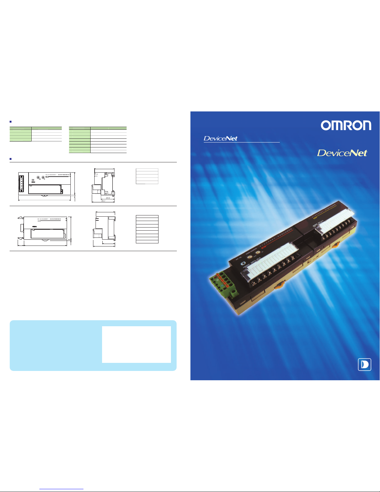
vailable Model
s
R
e
mot
e
I/O T
erminal
B
asi
c Unit
s
R
e
mot
e
I/O T
erminal
B
asi
c Unit
s
R
e
mot
e
I/O T
erminal
E
xpans
ion Unit
s
M
ode
l num
ber
D
RT2-ID1
6
D
RT2-ID16-
1
D
RT2-OD1
6
D
RT2-OD16-
1
Specificatio
n
16 inputs, NP
N
16 inputs, PNP
16 out
p
uts, NP
N
16 outputs, PNP
43.9
49.7
29.9
50
13
43.
9
0
3.1
11
5
One Basic Unit and one Expansion Unit can be combined freel
y.
3.1
16-point models: 94
8-point models: 66
R
e
mot
e
I/O T
erminal
E
xpans
ion Unit
M
ode
l num
ber
X
WT-ID
08
X
WT-ID08-
1
X
WT-OD0
8
XWT-OD08-1
XWT-ID16
XWT-ID16-1
X
WT-OD1
6
X
WT-OD16-
1
Specification
8
expansion inputs, NP
N
8
expansion inputs, PN
P
8
expansion outputs, NP
N
8 expansion outputs, PNP
16 expansion inputs, NPN
16 expansion inputs, PNP
16 ex
p
ansion outputs, NP
N
16 expansion outputs, PNP
R
e
mot
e
I/O T
erminal
s
DRT2-ID16(-1)/OD16(-1)
XWT-ID16(-1)/OD16(-1
)
XWT-ID08(-1)/OD08(-1
)
R
e
mot
e
I/O T
erminal
s
DRT2-ID16(-1)/OD16(-1)
XWT-ID16(-1)/OD16(-1
)
XWT-ID08(-1)/OD08(-1
)
XWT-ID16 -1
XWT-ID16
XWT-OD16 -1
XWT-OD16
XWT-ID08 -1
XWT-ID08
XWT-OD08 -1
XWT-OD08
Model number
DRT2-ID16 -1
DRT2-ID16
DRT2-OD16 -1
DRT2-OD16
Model number
A
dding a new dimensi
on t
o
with remot
e maintenan
ce
.
S
mar
t Sl
ave
s
D
imension
s
NODE ADDRESSM S NS
OMRON
C
orpora
tion
FA S
ystem
s
D
ivision
H.Q.
66 Matsumoto
Mishima-city, Shizuoka 411-8511
Japan
Tel:(81)55-977-9181
Fax:(81)55-977-9045
Authorized Distributor:
Note: Specifications subject to change without notice. Cat. No. R097-E1-01
Printed in Japan
0502-2M
R
e
gional
H
ea
dquarters
OM
R
ON EUROPE B.V.
Wegalaan 67-69, NL-2132 JD Hoofddorp
The Netherlands
Tel:(31)2356-81-300/Fax:(31)2356-81-388
OMRON ELECTR
ONICS LLC
1 East Commerce Drive, Schaumburg, IL 60173
U.S.A.
Tel:(1)847-843-7900 /Fax: (1)847-843-8568
OMRON ASIA PACIFIC PTE. LTD.
83 Clemenceau Avenue,
#11-01, UE Square,
Singapore 239920
Tel:(65)6835-3011/Fax :(65)6835-2711
Note: Do not use this document to operate the Unit.
Page 2
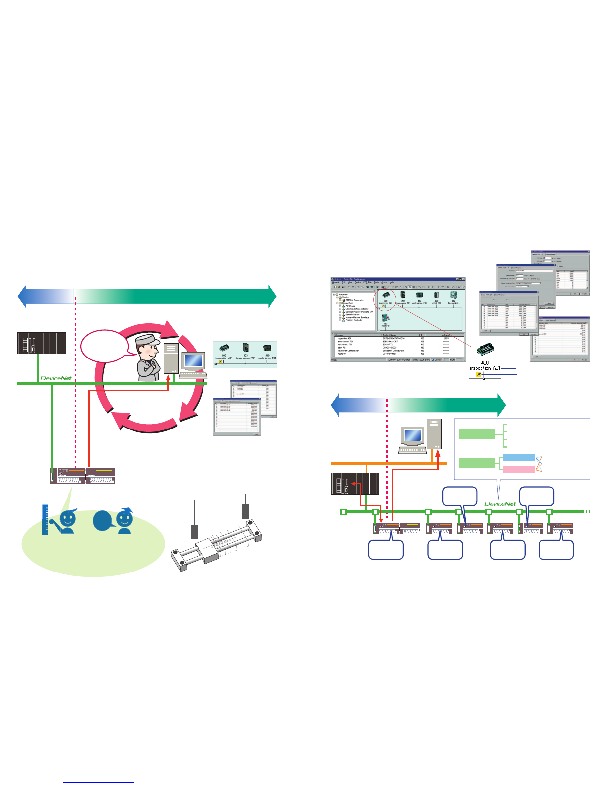
OMRON's DRT2-series Smart Slaves do not just input and output ON/OFF signals. They collect a variety
of value-added information to help increase the rate of operation without changing the wiring for
existing DeviceNet networks. In particular, they allow the separation of control systems and
maintenance systems so that maintenance systems can be created independently of control systems.
All data can be converted to electronic format and,
by combining with an OMRON PLC (CS/CJ Series),
checked directly from Ethernet or the Internet to
allow remote maintenance.
PLC
Configurator
Control I/O
DRT2-series
Smart Slave
Pneumatic valve
Maintenance information
E
a
sy-t
o-vie
w
D
ispla
y
2
3
Sensor
Cylinder
C
ontrol System
M
a
intenance System
M
a
intenance System
C
ontrol System
Operating time, contact operation
counter
M
achine
O
peration
M
onitored b
y
S
lav
e
F
aster
M
aintenance
W
ork
1
Information monitoring for
each Slave
Slave comment
Status confirmation using the status icon
M
a
intenance System
M
a
intenance System
C
ontrol System
C
ontrol System
MS NS NODE ADDRESS
DRT2-ID16
MS NS NODE ADDRESS
DRT2-ID16
MS NS NODE ADDRESS
DRT2-ID16
MS NS NODE ADDRESS
DRT2-ID16
MS NS NODE ADDRESS
DRT2-ID16
DRT2-series
Smart Slave
DeviceNet
Configurator
Ethernet
Maintenance information
PLC
Control
information
U
nit c
onduction
tim
e monito
r
(
See
not
e
.
)
O
perating tim
e
monito
r
C
ontac
t operation
c
ounter
(See
not
e
.
)
I/O
power status
monito
r
C
ommunica
tion erro
r
history monito
r
N
e
twork power
v
oltag
e monito
r
N
ot
e
: The contact operation counter function and the unit conduction time monitor function cannot be used simultaneously.
Operating time monitor
Contact operation counter
Unit conduction time monitor
Slave and connected component comments
I/O power status monitor
R
eliable e
quipment
startup
P
r
eve
nti
ve maintenance
o
f e
quipment
Reduced startup time
Reduced downtime
It's
tim
e for
moto
r
maintenance
!
W
hat i
s th
e
prese
nt
c
ommunica
tion
s
v
oltag
e
?
MS NS NODE ADDRESS
DRT2-ID16
ET-OD16
T
h
e cylinder's
spee
d i
s
incorrect
!
I
t might b
e tim
e
for a s
witch
inspec
tion
!
I
s th
e
I/O
power s
uppl
y
turned
ON
?
W
hat was th
e
cause
o
f th
e erro
r
?
U
s
e production sit
e informati
on i
n a variety o
f application
s
,
suc
h a
s maintenan
ce a
nd quality contro
l
.
C
ollec
t a variety o
f dat
a fro
m maintenan
ce systems withou
t
influenci
ng contro
l systems a
nd productivit
y
.
The Slave can hold comments,
allowing quick identification of
fault locations and faulty
devices.
The Slave Unit represents
machine operating time and
operational changes as data,
enabling monitoring without
increasing the load between
controllers.
By counting the number of
ON/OFF operations and the
total operating time, the Slave
Unit can provide notification
when maintenance is required.
1 2
3
4
5.
.
S
mar
t
M
easuri
ngSmar
t
C
ounti
ng
Configurator's maintenance mode screen
The Configurator's screen images may be changed without notice.
Maintenance is
required for
cylinder 23A in
inspection line A!
Communication error history
monitor
Network power voltage monitor
2 3
Page 3
Page 4
MS NS NODE ADDRESS
DRT2-ID16
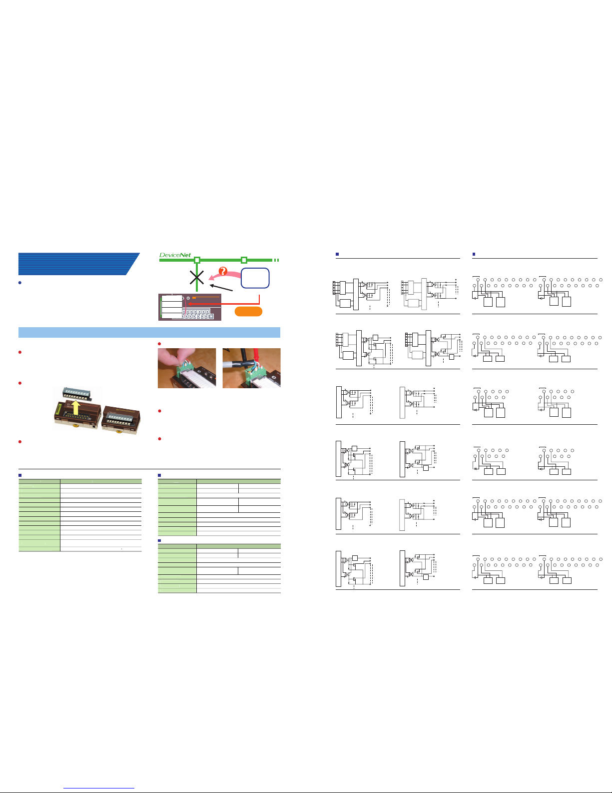
Information (i.e., communication error code and network
power voltage at the time) for four previous errors can be
recorded in the Slave. This error history can be read from
Smart Slaves that are removed from the network when
correcting an error, enabling more effective maintenance.
Smart Slave
Status when error occurred
First time
Second time
Third time
Fourth time
W
hat happened
whe
n the
communication
erro
r occurre
d
?
I
mproved Structura
l
F
lexibilit
y
I
mproved Structura
l
F
lexibilit
y
Network power volta
ge
I/O power supply volta
ge
Noise immunit
y
Vibration resistance
Shock resistance
Dielectric strength
Insulation resistance
Ambient operating temperature
Ambient operating humidity
Ambient atmosphere
Ambient storage temperature
Mounting method
Mounting strength
Screw tightening torqu
e
11 to 25 VDC (supplied from the communications connector)
20.4 to 26.4 VDC
(
24 VDC
15% to +10%
)
Conforms to IEC61000-4-4: 2 kV (power lines
)
10 to 50 Hz, 0.7-mm double amplitude
200m/s
2
500 VAC (between isolated circuits)
20 M min. (between isolated circuits)
–10 to 55 C
35% to 85%
No corrosive gases
–20 to +65 C
35-mm DIN track mounting
50 N (in directions other than the DIN track direction),
10 N
(
in the DIN track direction
)
M
3 (power supply, I/O terminals): 0.3 to 0.5
N
Mode
l num
ber
Internal I/O common processin
g
N
umber of I/O point
s
ON voltage
DRT2-ID1
6
DRT2-ID16-
1
16 input
sSp
ecification
Model number
I
nternal I/O common processing
Number of I/O points
Rated output current
DRT2-OD16
NPN
DRT2-OD16-1
PNP
16 outputs
0.5 A per point, 4.0 A per common
Specification
DRT2-ID16-1 (PNP)
XWT-OD16 (NPN)/OD16 -1 (PNP)
XWT-OD16 (NPN)
DRT2-OD16 (NPN)
DRT2-ID16 (NPN)
DRT2-ID16-1 (PNP)DRT2-ID16 (NPN)
DRT2-OD16-1 (PNP)
XWT-ID08 (NPN)/ID08-1 (PNP)
XWT-ID08 (NPN)
XWT-ID08-1 (PNP)
XWT-OD16-1 (PNP)
Remote I/O Terminals (Models with 16 Transistor Inputs)
DRT2-ID16 (NPN)/DRT2-ID16-1 (PNP)
Remote I/O Terminals (Models with 16 Transistor Inputs)
DRT2-ID16 (NPN)/DRT2-ID16-1 (PNP)
Remote I/O Terminals (Models with 16 Transistor Outputs)
DRT2-OD16 (NPN)/DRT2-OD16-1 (PNP)
DRT2-OD16 (NPN)
DRT2-OD16-1 (PNP)
Remote I/O Terminals (Models with 16 Transistor Outputs)
DRT2-OD16 (NPN)/DRT2-OD16-1 (PNP)
Remote I/O Terminal Expansion Units (Models with 8 Transistor Inputs)
XWT-ID08 (NPN)/ID08-1 (PNP)
XWT-ID08 (NPN)
XWT-ID08-1 (PNP)
Remote I/O Terminal Expansion Units (Models with 8 Transistor Inputs)
Remote I/O Terminal Expansion Units (Models with 8 Transistor Outputs)
Remote I/O Terminal Expansion Units (Models with 16 Transistor Inputs)
Remote I/O Terminal Expansion Units (Models with 16 Transistor Outputs)
XWT-OD16 (NPN)/OD16-1 (PNP)
XWT-OD16 (NPN)
XWT-OD16 -1 (PNP)
Remote I/O Terminal Expansion Units (Models with 16 Transistor Outputs)
XWT-OD08 (NPN)/OD08-1 (PNP)
XWT-OD08 (NPN)
XWT-OD08-1 (PNP)
Remote I/O Terminal Expansion Units (Models with 8 Transistor Outputs)
XWT-OD08 (NPN)/OD08-1 (PNP)
XWT-OD08 (NPN)
XWT-OD08-1 (PNP)
XWT-ID16 (NPN)/ID16-1 (PNP)
XWT-ID16 (NPN)
XWT-ID16-1 (PNP)
Remote I/O Terminal Expansion Units (Models with 16 Transistor Inputs)
XWT-ID16 (NPN)/ID16-1 (PNP)
XWT-ID16 (NPN)
XWT-ID16-1 (PNP)
The connector allows easy
checking using a tester.
V 24 VDC
0
1
G
V+
CAN H
DRAIN
CAN L
V–
Photocoupler
Photocoupler
Photocoupler
Photocoupler
Photocoupler
Photocoupler
Photocoupler
Photocoupler
Photocoupler
Photocoupler
Photocoupler
Photocoupler
Photocoupler
Photocoupler
Photocoupler
Photocoupler
Photocoupler
Photocoupler
Photocoupler
Photocoupler
Photocoupler
V 24 VDC
0
1
G
Physical layer
Physical layer
Physical layer
Non-insulated
DC-DC
converter
Non-insulated
DC-DC
converter
Non-insulated
DC-DC
converter
Non-insulated
DC-DC
converter
V+
CAN H
DRAIN
CAN L
V–
0
1
G
V 24 VDC
V+
CAN H
DRAIN
CAN L
V–
V101113125137149
15
G1022344658
6
24 VDC
Solenoid
111613
17
15
18
10712
8
14
9
Valve
0
1
G
V 24 VDC
V+
CAN H
DRAIN
CAN L
V–
V101113125137149
15
G1022344658
6
24 VDC
Solenoid
1116131715
18
10712814
9
Valve
V 24 VDC
0
1
G
V61738597
10
G10223446
5
24 VDC
V 24 VDC
0
1
G
V61738597
10
G10223446
5
24 VDC
0
1
G
V 24 VDC
V61738597
10
G10223446
5
24 VDC
0
1
G
V 24 VDC
V61738597
10
G10223446
5
24 VDC
V 24 VDC
0
1
G
V101113125137149
15
G1022344658
6
24 VDC
1116131715
18
10712814
9
V 24 VDC
0
1
G
0
1
G
V 24 VDC
V101113125137149
15
G1022344658
6
24 VDC
111613
17
15
18
10712
8
14
9
0
1
G
V 24 VDC
V101113125137149
15
G1022344658
6
24 VDC
1116131715
18
10712814
9
V101113125137149
15
G 0 2344658
6
24 VDC
1116131715
18
10712814
9
12
V101113125137149
15
G1022344658
6
24 VDC
1116131715
18
10712814
9
V101113125137149
15
G 0 2344658
6
24 VDC
I/O power supply
I/O power supply
I/O power supply
I/O power supply
I/O power supply
I/O power supply I/O power supply
I/O power supply
I/O power supply
I/O power supply
I/O power supply
I/O power supply
Three-wire sensor with
NPN output
(photoelectric sensor or
proximity sensor)
Two-wire sensor
(e.g., limit switch)
Three-wire sensor with
NPN output
(photoelectric sensor or
proximity sensor)
Two-wire sensor
(e.g., limit switch)
+–
+–
+–
+–
+–
+– +–
+–
+–
+–
+–
+–
1116131715
18
10712814
9
12
C
auses for communication errors ca
n b
e
monitore
d
.
C
ommunica
tion
E
rror
H
istory Monito
r
F
unction
R
ecorded in
th
e Sl
ave
S
malles
t in It
s
C
lass
The width of the Basic Unit is 115 mm (77% of 150-mm
DRT1-series models) and the width of the Expansion Unit is
94 mm, giving a total expanded width of 209 mm, making it
the smallest device of its class in the industry.
S
cre
w-less
C
lamp
C
ommunica
tion
s
C
onnector
s
E
asy
E
xpans
ion with
E
xpans
ion Unit
s
The Smart Slaves can be expanded easily by freely
combining Expansion Units with Basic Units using snap-on
mounting. This means less wiring work is required.
I
nput
F
ilter
F
unction
The influence of noise can be removed using the ON
response time. Also, very small pulses that are shorter
than the communications time can be handled using the
OFF response time.
F
unction for
H
a
ndling Sensor Inrush
C
urre
nt
In order to prevent incorrect input due to inrush current
when, for example, power to a sensor is turned ON, the
Slave can be set not to accept input for 100 ms after the
input power supply is turned ON.
E
asy Mounting a
nd
D
ismounting o
f Terminal
B
lock
s
Terminal blocks can
be mounted and
dismounted with
ease.
B
asi
c
F
unction
s
A
lso Improved
Wiring can be performed by
inserting post terminals.
G
enera
l Specification
s
I
nterna
l
C
irc
uit
D
iagrams
W
iring
D
iagrams
I
nput Specification
s
O
utput
S
p
ecifica
tion
s
1.2 V max. (0.5 A between each
output terminal and G)
1.2 V max. (0.5 A between each
output terminal and V)
Residual voltage
L
eakage curren
t
ON delay tim
e
OFF delay tim
e
N
umber of points per commo
n
0
.1 mA max
.
0
.5 ms max.
1.
5 ms ma
x.
16
p
oints per commo
n
5 VDC min. (between each input
terminal and V)
OFF voltage
1.0 mA max. per point (at 24 VDC)
6.0 mA max. per point at 24 VDC; 3.0 mA max. per point at 17 VDC
1.5 ms max.
1.
5
ms max
.
16 points per commo
n
OFF current
Input current
ON delay time
OFF delay tim
e
Number of points per commo
n
15 VDC min. (between each input
terminal and V)
5 VDC min. (between each input
terminal and G)
15 VDC min. (between each input
terminal and G)
6 7
Internal circuit
Internal circuit
Internal circuit
Internal circuit
Internal circuit
Internal circuit
Internal circuit
Internal circuit
Internal circuit
Internal circuit
Internal circuit
Physical layer
Internal circuit
Voltage
step-
down
Voltage
stepdown
Voltage
stepdown
Voltage
stepdown
Voltage
stepdown
Voltage
stepdown
Brown (Red)
Black (White)
Blue (Black)
Blue (Black)
Black (White)
Brown (Red)
Brown (White)
Blue (Black)
Blue (Black)
Brown (White)
Three-wire sensor with
NPN output
(photoelectric sensor or
proximity sensor)
Two-wire sensor
(e.g., limit switch)
Brown (Red)
Black (White)
Blue (Black)
Brown (White)
Blue (Black)
Three-wire sensor with
NPN output
(photoelectric sensor or
proximity sensor)
Blue (Black)
Black (White)
Brown (Red)
Blue (Black)
Brown (White)
Solenoid Valve Solenoid Valve
Three-wire sensor with
NPN output
(photoelectric sensor or
proximity sensor)
Two-wire sensor
(e.g., limit switch)
Brown (Red)
Black (White)
Blue (Black)
Brown (White)
Blue (Black)
Three-wire sensor with
NPN output
(photoelectric sensor or
proximity sensor)
Blue (Black)
Black (White)
Brown (Red)
Blue (Black)
Brown (White)
Two-wire sensor
(e.g., limit switch)
Solenoid Valve Solenoid Valve
Basic Units
Expansion Units
Specificatio
n
I
tem
I
tem
Item
 Loading...