

Omron DRT2-D16S, DRT2-ID16S-1, DRT2-MD16S, DRT2-MD16S-1, DRT2-ID16S Specifications
Remote Maintenance with DeviceNet Smart Slaves Equipped with
Industry-standard Sensor Connectors
Sensor Connector Terminal
Authorized Distributor:
Note: Specifications subject to change without notice. Cat. No. R105-E1-02
Printed in Japan
0304-1M
Note: Do not use this document to operate the Unit.
OMRON Corporation
FA Systems Division H.Q.
66 Matsumoto
Mishima-city, Shizuoka 411-8511
Japan
Tel: (81)55-977-9181
Fax: (81)55-977-9045
Regional Headquarters
OMRON EUROPE B.V.
Wegalaan 67-69, NL-2132 JD Hoofddorp
The Netherlands
Tel: (31)2356-81-300/Fax: (31)2356-81-388
OMRON ELECTRONICS LLC
1 East Commerce Drive, Schaumburg, IL 60173
U.S.A.
Tel: (1)847-843-7900/Fax: (1)847-843-8568
OMRON ASIA PACIFIC PTE. LTD.
83 Clemenceau Avenue,
#11-01, UE Square,
Singapore 239920
Tel: (65)6835-3011/Fax: (65)6835-2711
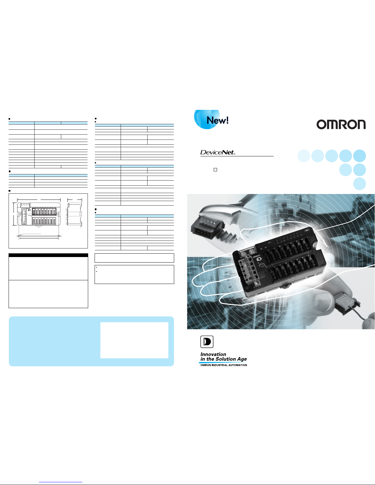
Smart Slave
DRT2- D16S(-1)
Model number Specifications
DRT2-ID16S
DRT2-ID16S-1
16 inputs, NPN
16 inputs, PNP
DRT2-MD16S
DRT2-MD16S-1
8 inputs/8 outputs, NPN
8 inputs/8 outputs, PNP
INPUT
0TO 7
MS
MODE ADDRESS
NS
U,ERR1
U,ERR2
IN
IN
08192103114125136147
15
INPUT
8TO15
95
88±0.2
Two 4.2 dia. or M4 holes
33.3
50
Mounting hole dimensions
Standard Models
Dimensions (mm)
General Specifications
Communications power
supply voltage
DRT2-MD16S (-1)DRT2-ID16S (-1)
Item
11 to 25 VDC (Supplied from communications connector.)
Input Specifications
16 Inputs
15 VDC min. (between each
input terminal and V)
15 VDC min. (between each
input terminal and G)
5 VDC max. (between each
input terminal and V)
5 VDC max. (between each
input terminal and G)
Item
Specifications
Model number
Internal I/O common processing
Number of I/O points
1.0 mA max.
11.0 mA max. per point at 24 VDC
3.0 mA min. per point at 11 VDC
16 inputs
DRT2-ID16S-1DRT2-ID16S
PNPNPN
90 g max 95 g max.
230 mA max. 135 mA max.
Dielectric strength
Noise immunity
Vibration resistance
500 VAC (between isolated circuits)
2 kV on power supply line (conforming to IEC61000-4-4)
10 to 56 Hz, 0.7-mm double amplitude,
56 to 150 Hz, acceleration: 50 m/s
2
150 m/s
2
M4 screw mounting or DIN Track mounting
M4 screws: 0.6 to 0.98 Nm
–10 to 55°C
35% to 85% (with no condensation)
–20 to 65°C.
I/O power supply voltage
Supplied from communications connector;
output supplied from external source.
Communications power
supply current consumption
Shock resistance
Mounting methods
Tightening torque
Ambient operating temperature
Ambient operating humidity
Storage temperature
Weight
OFF voltage
ON voltage
OFF current
Input current
ON delay time
OFF delay time
Number of circuits
1.5 ms max.
1.5 ms max.
16 inputs/common
Output Specifications
8 Inputs/8 Outputs
0.3 A per point, 2.4 A
per common
0.3 A per point, 1.6 A
per common
2 V max. at 0.3 ADC, between each
output terminal and G
2 V max. at 0.3 ADC, between each
output terminal and V
Item
Specifications
Model number
Internal I/O common processing
Number of I/O points
0.1 mA max.
8 outputs (8 to 15)
DRT2-MD16S-1DRT2-MD16S
PNPNPN
1.6 A min. per common2.4 A min. per common
Residual voltage and
current
Rated output
Leakage current
ON delay time
OFF delay time
Number of circuits
1.5 ms max.
1.5 ms max.
8 points per common
8 Inputs/8 Outputs
9 VDC min. (between each input
terminal and V) 1.5 ms max.
9 VDC min. (between each input
terminal and G)
5 VDC min. (between each input
terminal and V)
5 VDC min. (between each input
terminal and G)
Item
Specifications
Model number
Internal I/O common processing
Number of I/O points
1.0 mA max.
11 mA max. per point at 24 VDC
3.0 mA min. per point at 11 VDC
8 inputs (0 to 7)
DRT2-MD16S-1DRT2-MD16S
PNPNPN
OFF voltage
ON voltage
OFF current
Input current
ON delay time
OFF delay time
1.5 ms max.
1.5 ms max.
8 points per common
Number of circuits
Sensor short-circuit
detection current
100 mA min. (per point)
Load short-circuit detection
current
This catalog mainly provides information that is necessary for selecting suitable models, and
does not contain precautions for correct use. Always read the precautions and other
required information provided in product operation manuals before using the product.
The application examples provided in this catalog are for reference only. Check functions
and safety of the equipment before use.
Never use the products for any application requiring special safety requirements, such as
nuclear energy control systems, railroad systems, aviation systems, medical equipment,
amusement machines, vehicles, safety equipment, or other application involving serious risk
to life or property, without ensuring that the system as a whole has been designed to
address the risks, and that the OMRON products are properly rated and installed for the
intended use within the overall equipment or system.
Warranty and Limitations of Liability
WARRANTY
OMRON's exclusive warranty is that the products are free from defects in materials and
workmanship for a period of one year (or other period if specified) from date of sale by
OMRON.
OMRON MAKES NO WARRANTY OR REPRESENTATION, EXPRESS OR IMPLIED,
REGARDING NON-INFRINGEMENT, MERCHANTABILITY, OR FITNESS FOR PARTICULAR
PURPOSE OF THE PRODUCTS. ANY BUYER OR USER ACKNOWLEDGES THAT THE BUYER
OR USER ALONE HAS DETERMINED THAT THE PRODUCTS WILL SUITABLY MEET THE
REQUIREMENTS OF THEIR INTENDED USE. OMRON DISCLAIMS ALL OTHER WARRANTIES,
EXPRESS OR IMPLIED.
LIMITATIONS OF LIABILITY
OMRON SHALL NOT BE RESPONSIBLE FOR SPECIAL, INDIRECT, OR CONSEQUENTIAL
DAMAGES, LOSS OF PROFITS, OR COMMERCIAL LOSS IN ANY WAY CONNECTED WITH
THE PRODUCTS, WHETHER SUCH CLAIM IS BASED ON CONTRACT, WARRANTY,
NEGLIGENCE, OR STRICT LIABILITY.
In no event shall the responsibility of OMRON for any act exceed the individual price of the
product on which liability is asserted.
IN NO EVENT SHALL OMRON BE RESPONSIBLE FOR WARRANTY, REPAIR, OR OTHER
CLAIMS REGARDING THE PRODUCTS UNLESS OMRON'S ANALYSIS CONFIRMS THAT THE
PRODUCTS WERE PROPERLY HANDLED, STORED, INSTALLED, AND MAINTAINED AND
NOT SUBJECT TO CONTAMINATION, ABUSE, MISUSE, OR INAPPROPRIATE
MODIFICATION OR REPAIR.
Simple
Crimping
Simple
Crimping
All I/O points have a
common terminal, so an
intermediate terminal is not
needed!
Operation time monitor
Contact operation counter (See note.)
Unit conduction time monitor
Total ON time monitor (See note.)
Slave comment/ I/O comments
Network power voltage monitor
I/O power status monitor
Communications error history monitor
Input filter
Sensor inrush current prevention
Detection of sensor power short-circuit
Detection of external load short-circuit
Automatic baud rate
(With Industry-standard Sensor
Connectors (Male))
Extension Cables
E39-ECON M
(Female E-CON connector on
one end.)
E39-ECONW M
(Female E-CON connector on
one end, male E-CON connector
on the other end.)
The contact operation counter and total ON time monitor cannot be used simultaneously.
Model
Connector (e-CON) Terminal
Function
Input Input/output
1
2
3
4
Pin number
Signal name (color)
12 to 24 VDC (brown)
Open
0 V (blue)
Control output (black)
37104-3101-000FL
37104-3122-000FL
37104-3163-000FL
37104-2124-000FL
37104-2165-000FL
37104-2206-000FL
26 to 24 AWG (0.14 to 0.2 mm2); Outer diameter including insulation: 0.8 to 1.0 mm
26 to 24 AWG (0.14 to 0.2 mm
2
); Outer diameter including insulation: 1.0 to 1.2 mm
26 to 24 AWG (0.14 to 0.2 mm2); Outer diameter including insulation: 1.2 to 1.6 mm
22 to 20 AWG (0.3 to 0.5 mm
2
); Outer diameter including insulation: 1.0 to 1.2 mm
22 to 20 AWG (0.3 to 0.5 mm
2
); Outer diameter including insulation: 1.2 to 1.6 mm
22 to 20 AWG (0.3 to 0.5 mm
2
); Outer diameter including insulation: 1.6 to 2.0 mm
Model number Appropriate wire size
Specifications/Housing color
Red
Yellow
Orange
Green
Blue
Gray
1
2
3
4
1
2
3
4
Pin number
Extension Cable color
Brown
White
Blue
Black
Sensor model
E3T series
EE-SX series
Cable lengths
0.3 m, 0.5 m, or 2 m
0.3 m or 2 m
Sensor model
E3Z series
E39-ECON M
E39-ECONW M
Cable lengths
2 m or 5 m
0.5 to 2 m
(in 0.1-m increments)
1
2
3
4
Example model numbers
E3Z-T61-ECON 0.3m
E3T-FT11-ECON 2m
E39-ECON2M
E39-ECONW0.5M
V
NC
G1
IN0
V+
CAN H
DRAIN
CAN L
V–
V+
CAN H
DRAIN
CAN L
V–
V+
CAN H
DRAIN
CAN L
V–
V
NC
G1
IN1
Physical
layer
V1
NC
G
IN0
V1
NC
G
IN1
V+
CAN H
DRAIN
CAN L
V–
Physical
layer
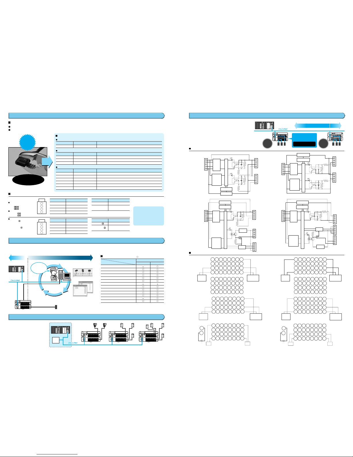
Internal circuits
DRT2-ID16S
(NPN)
DRT2-ID16S-1
(PNP)
Easy Wiring for I/O Connections
Compatible Connectors
The Compatible Connectors are sold separately.
Sumitomo 3M Connectors
1-1473562-4
1473562-4
2-1473562-4
28 to 24 AWG (0.08 to 0.2 mm2); Outer diameter including insulation: 0.9 to 1.0 mm
24 to 22 AWG (0.2 to 0.3 mm
2
); Outer diameter including insulation: 1.0 to 1.15 mm
22 to 20 AWG (0.3 to 0.5 mm
2
); Outer diameter including insulation: 1.15 to 1.35 mm
Model number Appropriate wire size
Specifications/Housing color
Red
Yellow
Blue
Tyco Electronics AMP Connectors
XN2A-1430
28 to 20 AWG (0.08 to 0.5 mm2); Outer diameter including insulation: 1.5 mm max.
Model number Appropriate wire size
Specifications
Spring clamp
OMRON Connectors
Maintain stable communications.
Maintain stable communications.
Input
shortcircuit
Output
shortcircuit
Short-circuits in the power supply for input
devices and output devices are detected for
each Unit. Notification of any short-circuits
that are deteced is provided as part of
status information. This allows stable and
continuous operation of the system.
Industry-standard Sensor Connectors
Detect Short-circuits to Prevent the System from Going Down
Smart Functions
Industry-standard sensor connectors simplify wiring because the connector's I/O wires can all be crimped at once.
The OMRON Sensors listed below are available with e-CON connectors already attached.
DC static
converter
(non-isolated)
Short-circuit
detection circuit
Internal circuits
Short-circuit
protection element
Short-circuit
protection element
Short-circuit
detection circuit
DC static
converter
(non-isolated)
DRT2-ID16S
(NPN)
DRT2-ID16S-1
(PNP)
V
NC
G1
IN
0
V
NC
G1
IN
1
V
NC
G2
IN
2
V
NC
G2
IN
3
V
NC
G3
IN
4
V
NC
G3
IN
5
V
NC
G4
IN
6
V
NC
G4
IN
7
V
NC
G5
IN
8
1
2
V
NC
G5
IN
9
V
NC
G6
IN
10
V
NC
G6
IN
11
V
NC
G7
IN
12
V
NC
G7
IN
13
V
NC
G8
IN
14
V
NC
G8
IN
15
Brown
(white)
Blue
(black)
V
NC
G
IN
0
V
NC
G
IN
1
V
NC
G
IN
2
V
NC
G
IN
3
V
NC
G
IN
4
V
NC
G
IN
5
V
NC
G
IN
6
V
NC
G
IN
7
V
NC
G
IN
8
V
NC
G
IN
9
V
NC
G
IN
10
V
NC
G
IN
11
V
NC
G
IN
12
V
NC
G
IN
13
V
NC
G
IN
14
V
NC
G
IN
15
3
4
1
2
3
4
1
2
3
4
1
2
3
4
Two-wire sensor
(such as a limit switch)
Two-wire sensor
(such as a limit switch)
Solenoid valve, etc. Solenoid valve, etc. Solenoid valve, etc.Solenoid valve, etc.
Two-wire sensor
(such as a limit switch)
Compatible Sensors
List of Functions
Photoelectric Sensors with
Built-in Amplifier
E3Z- -ECON
E3T- -ECON
Photomicrosensors
EE-SX77 -ECON
EE-SX87 -ECON
The Terminals provide smart functions that improve remote maintenance. A variety of information can be
collected for maintenance systems without influencing control systems and productivity.
: Supported; –: Not supported.
Input and output device
short-circuit deteced and
notification provided.
Detect and protect against
power supply short-circuits.
Internal Circuit Diagrams
Wiring Diagrams
Three-wire NPN-output
sensor (such as a
Photoelectric Sensor or
Proximity Sensor)
Three-wire PNP-output
sensor (such as a
Photoelectric Sensor or
Proximity Sensor)
Blue
(black)
Brown
(red)
Black
(white)
PLC
Configurator
Control I/O
DRT2 Series
Maintenance information
Easy-to-view Display
2
3
Sensor
Maintenance SystemControl System
Contact operation count monitor
Machine Operation
Monitored by Slave
Faster Maintenance
Work
1
The Slave can hold
comments, allowing quick
identification of fault
locations and faulty devices.
Maintenance is
required for
Sensor 23A in
inspection line A.
Programmable Controller
Sensor
Power
Supply
Reduced Wiring
Sensor Sensor
No power supply wiring is
required for input devices,
such as sensors.
Power supply wiring for
communications, Slaves, and I/O
devices can be unified into a single
wiring system.
DRT2-MD16S
(NPN)
DRT2-MD16S-1
(PNP)
V1
NC
G
IN0
V0
V0
G0
G0
NC
NC
G2
OUT0
Physical
layer
Physical
layer
V
NC
G1
IN0
V2
NC
NC
OUT0
DC static
converter
(non-isolated)
DC static
converter
(non-isolated)
Short-circuit
detection circuit
Short-circuit
detection circuit
Short-circuit
protection element
Short-circuit
protection element
V0
V0
G0
G0
Internal circuits
Internal circuits
Voltage
step-down
Voltage
step-down
Detection
circuit
Detection
circuit
DRT2-MD16S
(NPN)
DRT2-MD16S-1
(PNP)
V1
NC
G1
IN
0
V1
NC
IN
1
V2
NC
IN
2
V2
NC
IN
3
V3
NC
IN
4
V3
NC
IN
5
V4
NC
IN
6
V4
NC
IN
7
NC
G2
OUT
0
1
2
NC
G2
OUT
1
NC
G2
OUT
2
NC
G2
OUT
3
NC
G2
OUT
4
NC
G2
OUT
5
NC
G2
OUT
6
NC
NC NC NC NC NC NC NC NC
G2
OUT
7
3
4
1
2
3
4
G1
G1 G1G1G1 G1
G1
V0
G0
V1
NC
G1
IN
0
V1
NC
IN
1
V1
NC
IN
2
V1
NC
IN
3
V1
NC
IN
4
V1
NC
IN
5
V1
NC
IN
6
V1
NC
IN
7
V2
NC
NC
OUT
0
1
2
NC
NC
OUT
1
NC
NC
OUT
2
NC
NC
OUT
3
NC
NC
OUT
4
NC
NC
OUT
5
NC
NC
OUT
6
NC
NC
OUT
7
Brown
(white)
Blue
(black)
Two-wire sensor
(such as a limit switch)
Brown
(white)
Blue
(black)
Brown
(white)
Blue
(black)
Three-wire NPN-output
sensor (e.g., photoelectric
sensor or proximity
sensor)
Blue
(black)
Brown
(red)
Black
(white)
Three-wire NPN-output
sensor (such as a
Photoelectric Sensor or
Proximity Sensor)
Blue
(black)
Brown
(red)
Black
(white)
Blue
(black)
Brown
(red)
Black
(white)
3
4
1
2
3
4
G1
G2 G2G3G3 G4
G4
V2
V2
V2
V2
V2 V2
V2
V0
+
G0
–
+
–
 Loading...