

Page 1
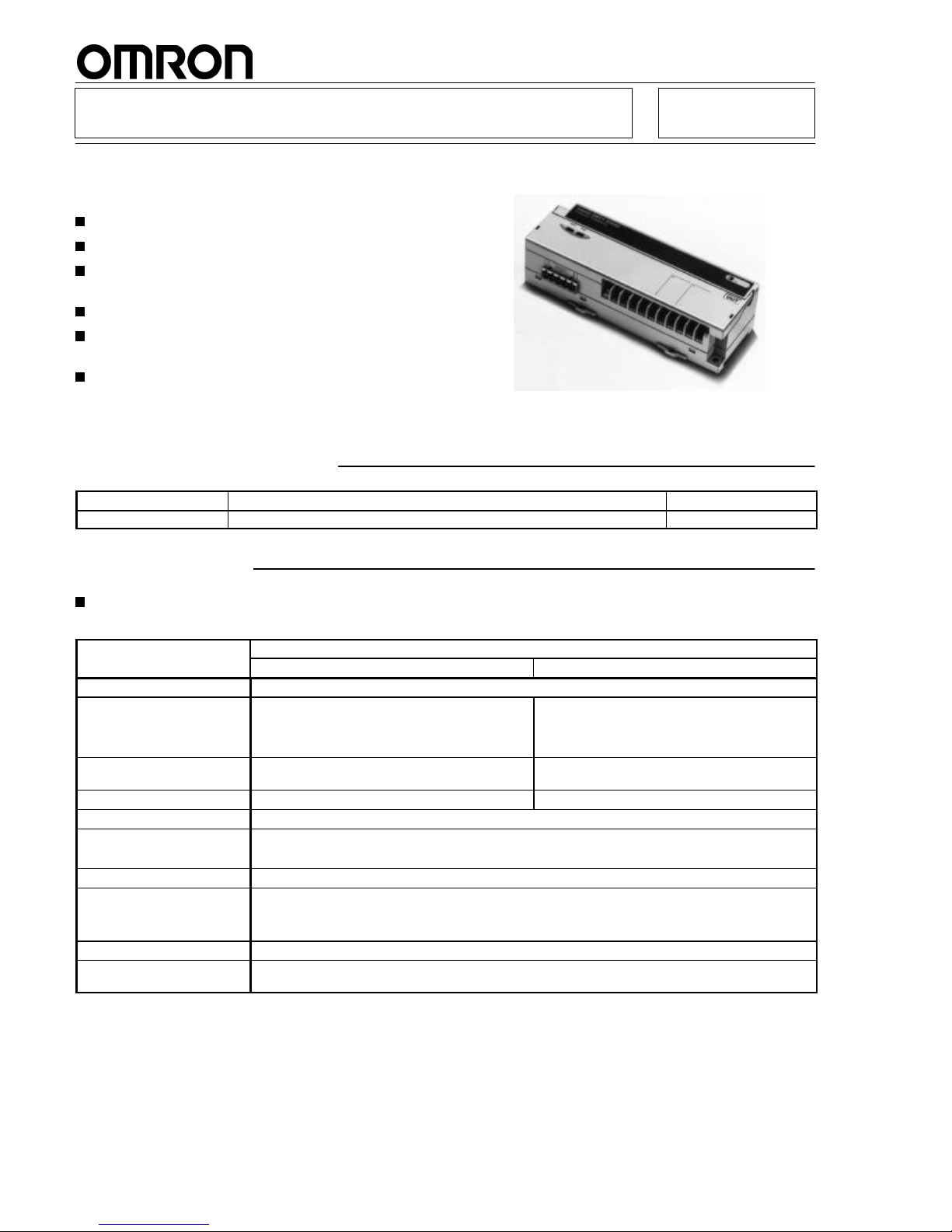
Analog Output Module
DRT1-DA02
I/O Interface Converts Binary Data into
Analog Output Data
Two outputs available.
High resolution of 1/6000.
Conversion is possible within a range of --5% to
150% full scale.
High conversion speed of 4 ms/two points.
Handles a wide range of outputs including 1 to 5 V,
0 to 10 V, --10 to 10 V, 4 to 20 mA, and 0 to 20 mA.
Bears the CE marking.
Ordering Information
Classification I/O points Model
Analog output Module 2 outputs (Occupies 2 output words of the Master.) DRT1-DA02
Specifications
Ratings
Output
Item Type
Voltage output Current output
Output points 2 points
Output type 1 to 5 V
0 to 10 V
--10 to 10 V
Allowable external output
load resistance
External output impedance 0.5 W max. ---
Resolution 1/6000 full scale
Overall accuracy 25°C : ±0.4% full scale
Conversion time 4 ms/2 points
Converted output data Binary data
Insulation resistance 20 MW min. at 250 VDC (between insulated circuits)
Insulation method Photocoupler insulation between outputs and communications lines (There is no insulation between
1 KW min. 600 W max.
0°C to 55°C: ±0.8% full scale
--10- to 10-V range: 8BB8 to 0BB8 full scale
Other signal ranges:0000 to 1770 full scale
output signals.)
0 to 20 mA
4 to 20 mA
114
Page 2
DRT1-DA02
DRT1-DA02
DRT1-DA02
Characteristics
Communications power supply
voltage
Internal power supply voltage 20.4 to 26.4 VDC (24 VDC
Current consumption Communications: 30 mA max. at 24 VDC
Noise immunity Power supply normal: ±600 V for 10 minutes with a pulse width of 100 ns to 1 ms
Vibration resistance 10 to 55 Hz, 1.5-mm double amplitude
Shock resistance Malfunction: 200 m/s2(approx. 20G)
Dielectric strength 500 VAC for 1 min (1-mA sensing current between insulated circuits)
Mounting method M4 screw mounting or 35-mm DIN track mounting
Mounting strength No damage when 50 N (approx. 5 kgf) pull load was applied for 10 s in all directions (10 N min.
Terminal strength No damage when 50 N (approx. 5 kgf) pull load was applied for 10 s in all directions
Ambient temperature Operating: 0°C to 55°C (with no icing or condensation)
Ambient humidity Operating: 35% to 85% (no condensation)
Weight 200 g max.
11 to 25 VDC (supplied from the communications connector)
+10%
/
)
--15%
Internal circuit: 150 mA max. at 24 VDC
Power supply common: ±1,500 V for 10 minutes with a pulse width of 100 ns to 1 ms
Destruction: 300 m/s2(approx. 30G)
(approx. 1 kgf) in the DIN track direction)
Storage: --25°C to 65°C (with no icing or condensation)
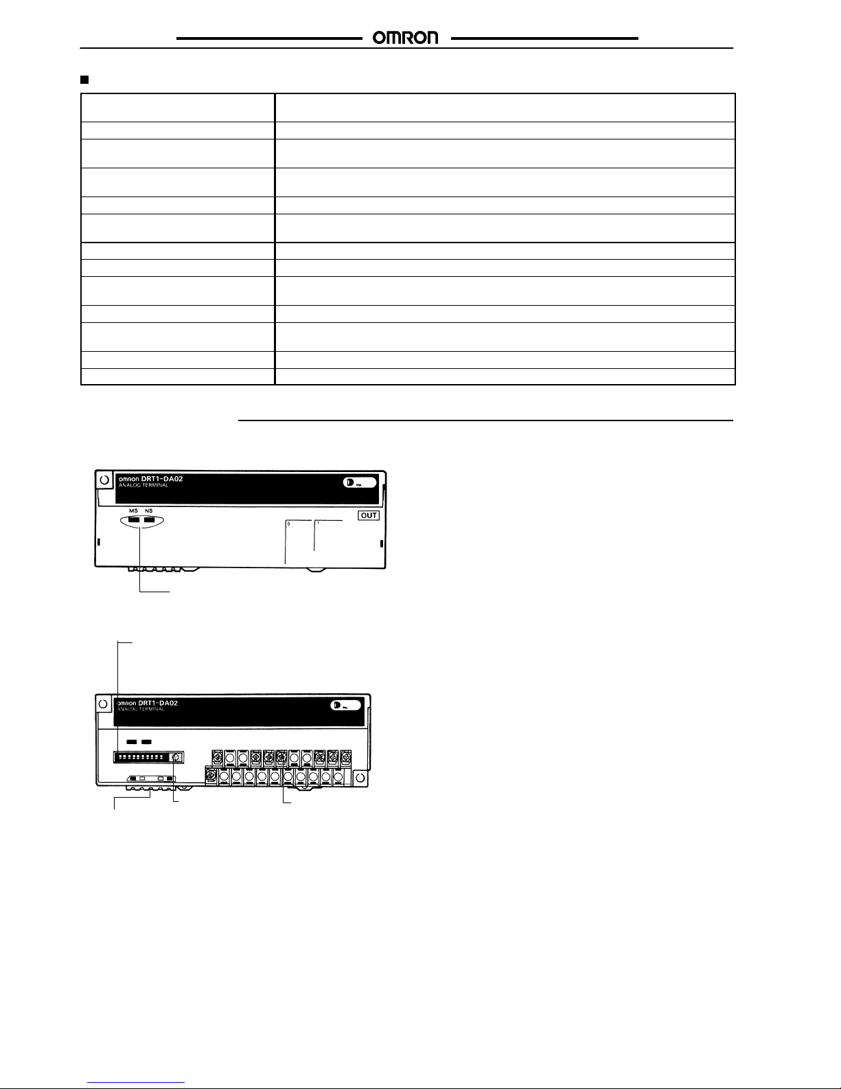
Nomenclature
Indicators
Indicates the status of the Slave and network
The DIP switch pins have the following functions:
Pins 1 to 6: Node number
Pins 7 and 8: Baud rate
Pin 9 and 10: Output status after communications error
Communications
Connector
Connects the network communications
cable. The communications power is
also supplied through this connector.
Rotary Switch
Sets the output ranges.
Terminal Block
Connects the output power supply and analog
outputs.
115
Page 3

DRT1-DA02
(73max.
)
Dimensions
Note: All units are in millimeters unless otherwise indicated.
DRT1-DA02
DRT1-DA02
50 max.
Wiring
DRT1-DA02
Internal circuit power supply
SOURCE
24 VDC
Mounting Holes
Two, 4.2 dia. or M4
Voltage output connection
150 max.
40 max.
Current output connection
Internal circuit
power supply
Terminal Arrangement
DRT1-DA02
116
External
device
24 VDC
24 VDC
External
device
0 0 0 1 1 1
Page 4

DRT1-DA02
Precautions
Refer to the DeviceNet Operation Manual (W267) before using the
Module.
· To prevent inductive noise, do not wire power lines or
high-tension lines along with or near the cables. Other
noise-prevention techniques, such as using shielding or
separate conduit/ducting, are also effective.
· Install the Module as far as possible from equipment that
generates strong high-frequency signals (such as high-frequency welders) and equipment that generates surges. Such
equipment can cause the Module to malfunction.
· Install surge absorbers or noise filters on nearby equipment that
generates noise, particularly equipment that has inductive
components such as motors, transformers, solenoids, or
magnetic coils.
· When using a noise filter in the power supply, check the voltage
and current and install the noise filter as close as possible to the
Module.
DRT1-DA02
NOTE: DIMENSIONS SHOWN ARE IN MILLIMETERS. To convert millimeters to inches divide by 25.4.
R
OMRON ELECTRONICS, INC.
One East Commerce Drive
Schaumburg, IL 60173
1-800-55-OMRON
Cat. No. P10FAX1A 6/00 Specifications subject to change without notice. Printed in U.S.A.
OMRON CANADA, INC.
885 Milner Avenue
Scarborough, Ontario M1B 5V8
416-286-6465
117
 Loading...