

Page 1
ID Tags
V680-D
@@
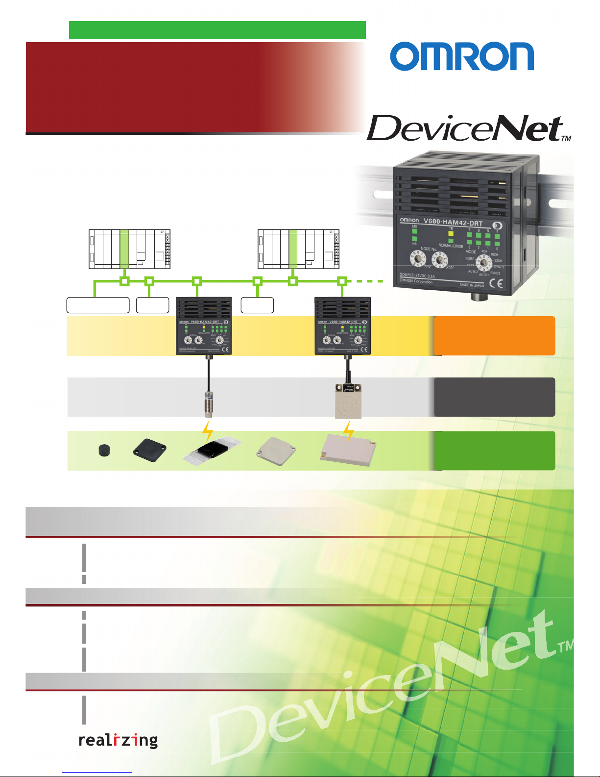
DeviceNet ID Slave
V680-HAM42-DRT
Antennas
V680-HS
@@
Powerful Functions in a Compact Size.
The compact size of 65 × 65 × 65 mm reduces installation space.
The DeviceNet ID Slave can communicate with ID Tags and Antennas that comply with ISO/IEC 18000-3 (ISO/IEC
15693) to enable a wide variety of applications.
The V680 Antenna comes with a maximum cable length of 12.5 m, allowing it to be installed in locations away from the
control panel.
Access Up to 58 Bytes of Data.
Improve Communications Performance with the Master Unit.
Operating modes include 4-byte, 26-byte, and 58-byte Access Modes, and a Noise Measurement Mode.
You get improved tact time, and simplified startup and maintenance.
V600-HAM42-DRT-compatible Access Modes allow the application of existing programs.
A special function greatly reduces communications data with the Master Unit of the PLC for even easier application.
The Antenna Cable is available in 2 m and 12.5 m lengths.
IP67 protection for FA environments.
Lineup includes 1K, 2K, 8K, and 32K ID Tags.
The wide lineup includes super-compact ID Tags with an 8-mm diameter that can be embedded in metal, as well as long-life ID Tags capable of 10 billion accesses.
Slave I/O I/O
Read and write up to 58 bytes of data.
DeviceNet makes information
management at the production site
simpler, more flexible, and more open.
V680-HAM42-DRT
V680 RFID
DeviceNet ID Slave
Take the V680 Overseas.
The V680 complies with international standards and radio wave regulations.
Radio wave regulation compliance is applicable to Japan, Europe, the U.S.A., and Canada. Radio wave regulation
compliance for China, Taiwan, South Korea, and Southeast Asia is pending.
Conforms to ISO/IEC 18000-3 (ISO/IEC 15693) Standards
Page 2
Authorized Distributor:
In the interest of product improvement,
specifications are subject to change without notice.
Cat. No. Q161-E1-01
OMRON Industrial Automation Global: www.ia.omron.com
Printed in Japan
0308-0.3C (0308) (C)
OMRON Corporation
Industrial Automation Company
Regional Headquarters
OMRON EUROPE B.V.
Sensor Business Unit
Carl-Benz-Str. 4, D-71154 Nufringen,
Germany
Tel: (49) 7032-811-0/Fax: (49) 7032-811-199
OMRON ELECTRONICS LLC
One Commerce Drive Schaumburg,
IL 60173-5302 U.S.A.
Tel: (1) 847-843-7900/Fax: (1) 847-843-7787
OMRON ASIA PACIFIC PTE. LTD.
No. 438A Alexandra Road # 05-05/08 (Lobby 2),
Alexandra Technopark, Singapore 119967
Tel: (65) 6835-3011/Fax: (65) 6835-2711
OMRON (CHINA) CO., LTD.
Room 2211, Bank of China Tower,
200 Yin Cheng Zhong Road,
PuDong New Area, Shanghai, 200120, China
Tel: (86) 21-5037-2222/Fax: (86) 21-5037-2200
Sensing Devices Division H.Q.
Industrial Sensors Division
Shiokoji Horikawa, Shimogyo-ku,
Kyoto, 600-8530 Japan
Tel: (81)75-344-7022/Fax: (81)75-344-7107
This document provides information mainly for selecting suitable models. Please read the User’s Manual (Cat. No. Z278) carefully for information that the
user must understand and accept before purchase, including information on warranty, limitations of liability, and precautions.
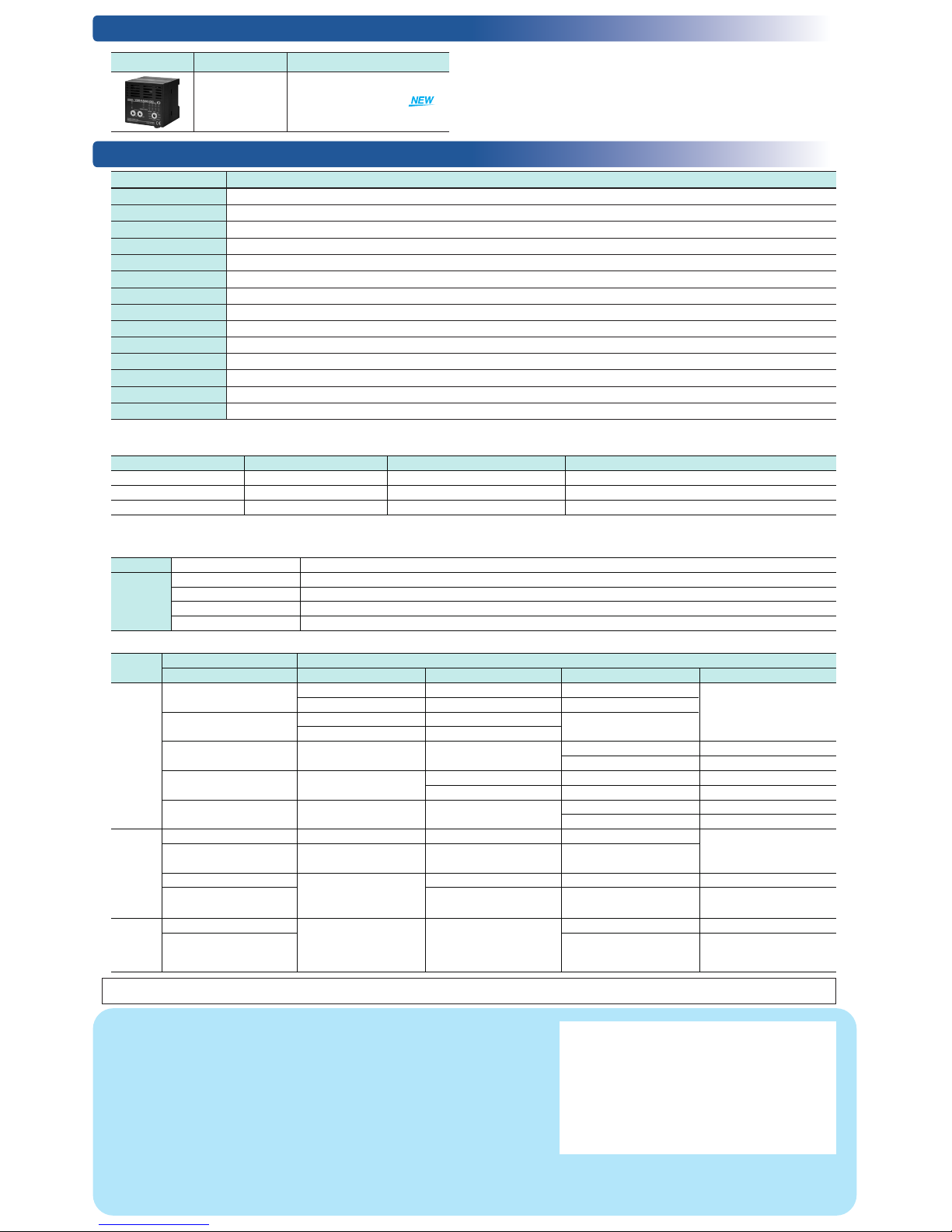
Ordering Information
Ratings and Performance
Appearance Size Model
65 × 65 × 65 mm
(excluding protrusions)
V680-HAM42-DRT
Note: For details, refer to the User's Manual (Cat. No. Z278).
Note 1. The V600-compatible Trigger and Auto Modes can be used with the same I/O settings and control methods that are used with the V600-HAM42-DRT.
2. For details, refer to the User's Manual (Cat. No. Z278).
V680-HAM42-DRT
24 VDC (−15% to 10%) including 10% ripple (p-p)
4 W max. (Current consumption of 200 mA max. at power supply voltage of 24 VDC)
−10 to 55°C (with no icing)
−25 to 65°C (with no icing)
25% to 85% (with no condensation; ambient operating temperature is 40°C max. at humidity of 85%)
20 MΩ min. (at 500 VDC) between all terminals excluding the ground terminal and the case
1,000 VAC (50/60 Hz) for 1 minute between all terminals excluding the ground terminal and the case
Vibration resistance
10 to 150 Hz, 0.2-mm double amplitude at 15 m/s
2
acceleration with 10 sweeps in X, Y and Z directions for 8 minutes each
150 m/s
2
in X, Y, and Z directions 3 times each (18 times in total)
IEC 60529, IP20
Polycarbonate (PC) resin, ABS resin
Approx. 150 g
DIN Track
Supply voltage
One channel (V680-HS@@)Connectable Antennas
Power consumption
Ambient operating temperature
Ambient storage temperature
Ambient operating humidity
Insulation resistance
Dielectric strength
Shock resistance
Degree of protection
Materials
Weight
Mounting
Transmission Distance Specifications
Commands (4-byte, 26-byte, 58-byte Access Mode)
Operating Modes
(Unit: mm)
ID Tag
V680-HAM42-DRT
V680-HS51 V680-HS52 V680-HS63 V680-HS65
V680-D1KP52MT
Read: 0.5 to 6.5 mm (axial deviation ±2) Read: 0.5 to 9.0 mm (axial deviation ±2) Read: 0.5 to 12.0 mm (axial deviation ±2)
Write: 0.5 to 6.0 mm (axial deviation ±2) Write: 0.5 to 8.5 mm (axial deviation ±2) Write: 0.5 to 9.5 mm (axial deviation ±2)
V680-D1KP52MT
Read: 0.5 to 3.5 mm (axial deviation ±2) Read: 0.5 to 4.5 mm (axial deviation ±2)
(embedded in metallic surface: steel)
Write: 0.5 to 3.0 mm (axial deviation ±2) Write: 0.5 to 4.0 mm (axial deviation ±2)
V680-D1KP66T
Read/Write: 1.0 to 17.0 mm (axial deviation ±2)
Read: 5.0 to 30.0 mm (axial deviation ±10) Read: 5.0 to 47.0 mm (axial deviation ±10)
Write: 5.0 to 25.0 mm (axial deviation ±10) Write: 5.0 to 42.0 mm (axial deviation ±10)
V680-D1KP66MT
Read: 1.0 to 16.0 mm (axial deviation ±2) Read: 5.0 to 25.0 mm (axial deviation ±10) Read: 5.0 to 25.0 mm (axial deviation ±10)
(flush-mounted on metallic surface: steel)
Write: 1.0 to 14.0 mm (axial deviation ±2) Write: 5.0 to 20.0 mm (axial deviation ±10) Write: 5.0 to 20.0 mm (axial deviation ±10)
V680-D1KP66T-SP
Read/Write: 1.0 to 15.0 mm (axial deviation ±2)
Read: 5.0 to 25.0 mm (axial deviation ±10) Read: 5.0 to 42.0 mm (axial deviation ±10)
Write: 5.0 to 20.0 mm (axial deviation ±10) Write: 5.0 to 37.0 mm (axial deviation ±10)
V680-D2KF52M
Read/Write: 0.5 to 5.5 mm (axial deviation ±2) Read/Write: 0.5 to 8.0 mm (axial deviation ±2) Read/Write: 0.5 to 9.5 mm (axial deviation ±10)
V680-D2KF52M
(embedded in metallic surface: steel)
Read/Write: 0.5 to 3.5 mm (axial deviation ±2) Read/Write: 0.5 to 3.0 mm (axial deviation ±2)
V680-D2KF67
Read/Write: 1.0 to 17.0 mm (axial deviation ±2) Read/Write: 7.0 to 30.0 mm (axial deviation ±10) Read/Write: 5.0 to 42.0 mm (axial deviation ±10)
V680-D2KF67M
(flush-mounted on metallic surface: steel)
Read/Write: 1.0 to 16.0 mm (axial deviation ±2) Read/Write: 6.0 to 25.0 mm (axial deviation ±10) Read/Write: 5.0 to 25.0 mm (axial deviation ±10)
V680-D8KF68/-D32KF68
Read/Write: 5.0 to 45.0 mm (axial deviation ±10) Read/Write: 5.0 to 75.0 mm (axial deviation ±10)
V680-D8KF68/-D32KF68
Read/Write: 5.0 to 35.0 mm (axial deviation ±10) Read/Write: 5.0 to 55.0 mm (axial deviation ±10)
(Special attachment provided;
flush-mounted on metallic surface: steel)
Symbol Description
Maximum number of bytes accessible in ID Tag
Words allocated in Master Unit
4CH 4-byte Access Mode Read: 4 bytes/Write: 4 bytes
IN: 4 words OUT: 4 words (PLC inputs: 64 points, PLC outputs: 64 points)
16CH 26-byte Access Mode Read: 26 bytes/Write: 26 bytes
IN: 16 words OUT: 16 words (PLC inputs: 256 points, PLC outputs: 256 points)
32CH 58-byte Access Mode Read: 58 bytes/Write: 58 bytes
IN: 32 words OUT: 32 words (PLC inputs: 512 points, PLC outputs: 512 points)
Reading READ
Data in the ID Tag memory is read by specifying the memory address and the number of bytes to process. (The number of bytes can be specified using the Access Mode.)
WRITE
Data is written to the ID Tag by specifying the memor y address, number of bytes to process, and the data. (The number of bytes can be specified using the Access Mode.)
Writing
BIT SET Previously specified bits (i.e., bits that are turned ON) are turned ON in the ID Tag address specified for BIT SET.
BIT CLEAR Previously specified bits (i.e., bits that are turned ON) are tur ned OFF in the ID Tag address specified for BIT CLEAR.
DATA FILL The specified continuous memory addresses in the ID Tag are filled with the same data.
---
---
---
---
---
---
---
---
---
---
Item Model
Amplifier
Antenna
Note: For applicable V680 Antennas and ID Tags and for more information on the
V680-HAM42-DRT, refer to the Datasheet (Cat. No.: Q160) and the User’s
Manual (Cat. No.: Z278).
1-Kbyte
memory
2-Kbyte
memory
8-/32-Kbyte
memory
 Loading...