

Page 1
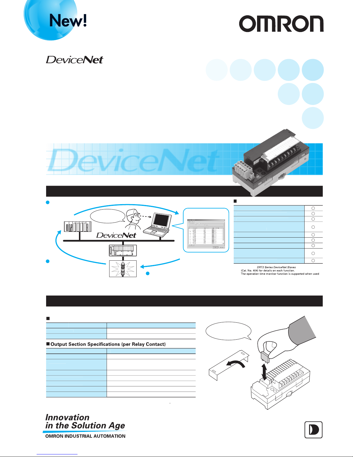
Smart Slaves with remote maintenance functions
now include Relay Output Terminals.
Smart Slaves
Relay Output
Remote I/O Terminal
DRT2-ROS16
The best for preventive maintenance.
Compatible with large-capacity output devices.
Function
s
Contact operations counte
r
Unit ON time monito
r functi
on
T
otal ON time monito
r functi
on
Slave comment/connected device
comment function
Network power supply voltage monito
r
Addition of Expansion I/O Units
Communications error log
Shared I/O and communications
p
ower suppl
y
B
aud rate auto-detection
Smart Slave Functions
PLC
Personal
computer
Contact operations
counter monitor
Remote I/O Terminal
Relay Output Unit
Relays need
replacing soon.
Indicator light
I
tem
Mounted rela
y
R
ated load
Rated carry curren
t
Max. contact volta
ge
Max. con
tact current
Max. switching capacit
y
Min. applicable load (reference value
)
Specificatio
n
NY-5W-L-IE (5 VDC
)
Resistive load; 2 A at 250 VAC,8 A per common;
2 A at 30 VDC, 8 A
p
er common
Note
: The rated carrying current is 3 A maximum per contact with 10 A per common. But then there may not be
more than 4 contacts per common switch ON. The ambient temperature must be below 4
5
C.
Slim power relays (5 mm width
)
I
tem
Mechanical lif
e
El
ectrica
l lif
e
Lif
e
20 million operations min
.
100,000 operations min
.
Life of Mounted Rela
ys
Maintenance capabilities enhanced by replaceable relays.
Easy rela
y
replacement
!
The slave
monitors the number of
times a relay has switched
and signals the PLC when
a set maximum is reached.
1
Easy-to-read Configurator
displays.
2
In-time preventive
maintenance
3
N
ote
: Refer to th
e
Op
eration Manual
together with an Input Expansion Unit
.
3 A (See note.
)
250 VAC, 125 VD
C
3 A
750 VAC, 90 VDC
5 VDC
,
1 m
A
New Product News
Page 2
I
tem
Communications
power supply volta
ge
Communications power
current consumptio
n
Noise immunity
Vibration resistance
Shock resistance
Dielectric strength
Insulation resistance
Ambient operating
temperature
Ambient humidity
Ambient environment
Ambient storage
temperature
Mounting method
Screw tightenin
g
torqu
e
Weigh
t
11 to 25 VDC (Supplied from the communications
connector.
)
395 mA
Conforms to IEC61000-4-4, 2 kV (power line)
10 to 55 Hz, 0.7-mm double amplitude
100 m/s
2
500 VAC (between isolated circuits)
20 MΩ min.
–10 to 55°C
Operating: 25% to 85% (with no condensation)
Must be free from corrosive gases.
–25 to 65°C
35-mm DIN Track mounting
0.26 to 0.3 N
M3 (screw terminals): 0.3 to 0.5
N
m
260 g max
.
M
ode
l num
ber
DRT2-ROS1
6
Expansion Systems
XWT-series Expansion I/O Units are easily added. This allows free expansion of contacts.
Separate wiring of I/O power supply to Expansion I/O Units is required. Note: Refer to the manual for details on the XWT Series.
Addition of Expansion Units
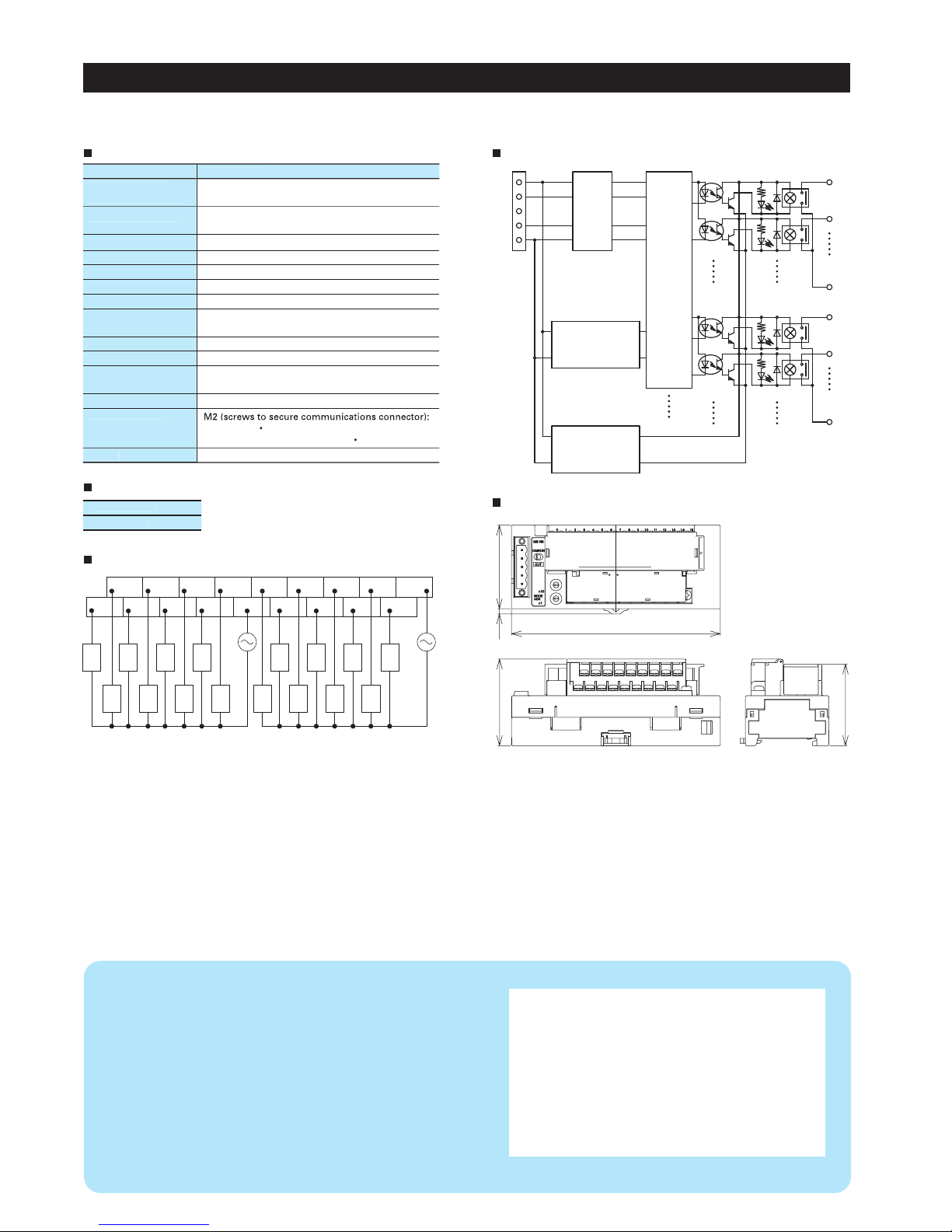
503.1
125
51.8
48.8
OMRON Corporation
FA Systems Division H.Q.
66 Matsumoto
Mishima-city, Shizuoka 411-8511
Japan
Tel: (81)55-977-9181
Fax: (81)55-977-9045
Authorized Distributor:
Note: Specifications subject to change without notice. Cat. No. R109-E1-01
Printed in Japan
0603-1M
Regional Headquarters
OMRON EUROPE B.V.
Wegalaan 67-69, NL-2132 JD Hoofddorp
The Netherlands
Tel: (31)2356-81-300/Fax: (31)2356-81-388
OMRON ELECTRONICS LLC
1 East Commerce Drive, Schaumburg, IL 60173
U.S.A.
Tel: (1)847-843-7900/Fax: (1)847-843-8568
OMRON ASIA PACIFIC PTE. LTD.
83 Clemenceau Avenue,
#11-01, UE Square,
Singapore 239920
Tel: (65)6835-3011/Fax: (65)6835-2711
Note: Do not use this document to operate the Unit.
Common S
p
ecification
s
Standard Models
Wirin
g
Internal Circuit Diagram
Dimensions
Specificatio
n
Physical
layer
V+
CAN H
DRAIN
CAN L
V–
Non-insulated
DC-DC converter
for internal circuit
Non-insulated
DC-DC converter
for relay drive
Internal
circuits
Photocoupler
Photocoupler
Photocoupler
Photocoupler
NY-5W-K-IE
5 VDC
NY-5W-K-IE
5 VDC
0
1
COM 0
8
9
COM 1
+
–
AC power
supply
(DC power
can also be
used.)
AC power
supply
(DC power
can also be
used.)
OUT
1
OUT0OUT2OUT4OUT6COM0 OUT9OUT11OUT13OUT
15
OUT3OUT5OUT7OUT8OUT10OUT12OUT14COM1
Load
Load
Load
Load
Load
Load
Load
Load
Load
Load
Load
Load
Load
Load
Load
Load
 Loading...