

Page 1

Cat. No. W381-E1-02
3G8F7-DRM21-E
DeviceNet PCI Board
OPERATION MANUAL
Page 2

3G8F7-DRM21-E DeviceNet PCI Board
Operation Manual
Revised July 2005
Page 3

iv
Page 4

Notice:
r
f
OMRON products are manufactured for use according to proper procedures by a qualified operator
and only for the purposes described in this manual.
The following conventions are used to indicate and classify precautions in this manual. Always heed
the information provided with them. Failure to heed precautions can result in injury to people or damage to property.
!DANGER Indicates an imminently hazardous situation which, if not avoided, will result in death or
serious injury. Additionally, there may be severe property damage.
!WARNING Indicates a potentially hazardous situation which, if not avoided, could result in death or
serious injury. Additionally, there may be severe property damage.
!Caution Indicates a potentially hazardous situation which, if not avoided, may result in minor or
moderate injury, or property damage.
OMRON Product References
All OMRON products are capitalized in this manual. The word “Unit” is also capitalized when it refers to
an OMRON product, regardless of whether or not it appears in the proper name of the product.
The abbreviation “Ch,” which appears in some displays and on some OMRON products, often means
“word” and is abbreviated “Wd” in documentation in this sense.
Visual Aids
The following headings appear in the left column of the manual to help you locate different types of
information.
OMRON, 2000
All rights reserved. No part of this publication may be reproduced, stored in a retrieval system, or transmitted, in any form, o
by any means, mechanical, electronic, photocopying, recording, or otherwise, without the prior written permission o
OMRON.
No patent liability is assumed with respect to the use of the information contained herein. Moreover, because OMRON is constantly striving to improve its high-quality products, the information contained in this manual is subject to change without
notice. Every precaution has been taken in the preparation of this manual. Nevertheless, OMRON assumes no responsibility
for errors or omissions. Neither is any liability assumed for damages resulting from the use of the information contained in
this publication.
Note Indicates information of particular interest for efficient and convenient opera-
tion of the product.
1,2,3... 1. Indicates lists of one sort or another, such as procedures, checklists, etc.
v
Page 5

vi
Page 6

TABLE OF CONTENTS
PRECAUTIONS. . . . . . . . . . . . . . . . . . . . . . . . . . . . . . . . . . . xiii
1 Intended Audience . . . . . . . . . . . . . . . . . . . . . . . . . . . . . . . . . . . . . . . . . . . . . . . . . . . . . . . . xiv
2 General Precautions . . . . . . . . . . . . . . . . . . . . . . . . . . . . . . . . . . . . . . . . . . . . . . . . . . . . . . . xiv
3 Safety Precautions . . . . . . . . . . . . . . . . . . . . . . . . . . . . . . . . . . . . . . . . . . . . . . . . . . . . . . . . xiv
4 Operating Environment Precautions. . . . . . . . . . . . . . . . . . . . . . . . . . . . . . . . . . . . . . . . . . . xv
5 Application Precautions . . . . . . . . . . . . . . . . . . . . . . . . . . . . . . . . . . . . . . . . . . . . . . . . . . . . xvi
6 Conformance to EC Directives . . . . . . . . . . . . . . . . . . . . . . . . . . . . . . . . . . . . . . . . . . . . . . . xvii
7 Components . . . . . . . . . . . . . . . . . . . . . . . . . . . . . . . . . . . . . . . . . . . . . . . . . . . . . . . . . . . . . xviii
SECTION 1
Introduction . . . . . . . . . . . . . . . . . . . . . . . . . . . . . . . . . . . . . . 1
1-1 Product Configuration . . . . . . . . . . . . . . . . . . . . . . . . . . . . . . . . . . . . . . . . . . . . . . . . . . . . . 2
1-2 DeviceNet PCI Board. . . . . . . . . . . . . . . . . . . . . . . . . . . . . . . . . . . . . . . . . . . . . . . . . . . . . . 2
1-3 Scanner SDK Functions and Features . . . . . . . . . . . . . . . . . . . . . . . . . . . . . . . . . . . . . . . . . 3
1-4 Scanner SDK Functions . . . . . . . . . . . . . . . . . . . . . . . . . . . . . . . . . . . . . . . . . . . . . . . . . . . . 4
1-5 System Configuration. . . . . . . . . . . . . . . . . . . . . . . . . . . . . . . . . . . . . . . . . . . . . . . . . . . . . . 7
1-6 Specifications . . . . . . . . . . . . . . . . . . . . . . . . . . . . . . . . . . . . . . . . . . . . . . . . . . . . . . . . . . . . 8
1-7 Board Components. . . . . . . . . . . . . . . . . . . . . . . . . . . . . . . . . . . . . . . . . . . . . . . . . . . . . . . . 10
1-8 Preparation for Operation. . . . . . . . . . . . . . . . . . . . . . . . . . . . . . . . . . . . . . . . . . . . . . . . . . . 11
SECTION 2
Software Installation . . . . . . . . . . . . . . . . . . . . . . . . . . . . . . . 13
2-1 Installation Procedure. . . . . . . . . . . . . . . . . . . . . . . . . . . . . . . . . . . . . . . . . . . . . . . . . . . . . . 14
2-2 Installing the Board in the Computer . . . . . . . . . . . . . . . . . . . . . . . . . . . . . . . . . . . . . . . . . . 14
2-3 Installing the Drivers . . . . . . . . . . . . . . . . . . . . . . . . . . . . . . . . . . . . . . . . . . . . . . . . . . . . . . 16
2-4 Installing the Scanner SDK Software. . . . . . . . . . . . . . . . . . . . . . . . . . . . . . . . . . . . . . . . . . 23
2-5 DeviceNet Connections . . . . . . . . . . . . . . . . . . . . . . . . . . . . . . . . . . . . . . . . . . . . . . . . . . . . 29
SECTION 3
Using API Functions . . . . . . . . . . . . . . . . . . . . . . . . . . . . . . . 35
3-1 Application Development Environments . . . . . . . . . . . . . . . . . . . . . . . . . . . . . . . . . . . . . . . 36
3-2 API Functions. . . . . . . . . . . . . . . . . . . . . . . . . . . . . . . . . . . . . . . . . . . . . . . . . . . . . . . . . . . . 36
3-3 Checking Events. . . . . . . . . . . . . . . . . . . . . . . . . . . . . . . . . . . . . . . . . . . . . . . . . . . . . . . . . . 38
3-4 Checking for Errors . . . . . . . . . . . . . . . . . . . . . . . . . . . . . . . . . . . . . . . . . . . . . . . . . . . . . . . 39
3-5 Parameters . . . . . . . . . . . . . . . . . . . . . . . . . . . . . . . . . . . . . . . . . . . . . . . . . . . . . . . . . . . . . . 39
3-6 Using I/O Communications Functions. . . . . . . . . . . . . . . . . . . . . . . . . . . . . . . . . . . . . . . . . 42
3-7 Using the Explicit Message Client Function . . . . . . . . . . . . . . . . . . . . . . . . . . . . . . . . . . . . 43
3-8 Using the Explicit Message Server Function . . . . . . . . . . . . . . . . . . . . . . . . . . . . . . . . . . . . 46
3-9 Reset Function . . . . . . . . . . . . . . . . . . . . . . . . . . . . . . . . . . . . . . . . . . . . . . . . . . . . . . . . . . . 47
3-10 Error Log Functions . . . . . . . . . . . . . . . . . . . . . . . . . . . . . . . . . . . . . . . . . . . . . . . . . . . . . . . 48
3-11 PC Watchdog Timer Management Function . . . . . . . . . . . . . . . . . . . . . . . . . . . . . . . . . . . . 48
vii
Page 7

TABLE OF CONTENTS
SECTION 4
API Function Reference . . . . . . . . . . . . . . . . . . . . . . . . . . . . . 51
4-1 Function Lists . . . . . . . . . . . . . . . . . . . . . . . . . . . . . . . . . . . . . . . . . . . . . . . . . . . . . . . . . . . . 52
4-2 Board Status. . . . . . . . . . . . . . . . . . . . . . . . . . . . . . . . . . . . . . . . . . . . . . . . . . . . . . . . . . . . . . 55
4-3 Board Management API Functions . . . . . . . . . . . . . . . . . . . . . . . . . . . . . . . . . . . . . . . . . . . . 56
4-4 Master Function API Functions. . . . . . . . . . . . . . . . . . . . . . . . . . . . . . . . . . . . . . . . . . . . . . . 62
4-5 Slave Function API Functions. . . . . . . . . . . . . . . . . . . . . . . . . . . . . . . . . . . . . . . . . . . . . . . . 74
4-6 Explicit Message API Functions . . . . . . . . . . . . . . . . . . . . . . . . . . . . . . . . . . . . . . . . . . . . . . 79
4-7 Maintenance API Functions . . . . . . . . . . . . . . . . . . . . . . . . . . . . . . . . . . . . . . . . . . . . . . . . . 89
SECTION 5
Sample Programs . . . . . . . . . . . . . . . . . . . . . . . . . . . . . . . . . . 99
5-1 Sample . . . . . . . . . . . . . . . . . . . . . . . . . . . . . . . . . . . . . . . . . . . . . . . . . . . . . . . . . . . . . . . . . . 100
5-2 Using DeviceNet Scanner Demo. . . . . . . . . . . . . . . . . . . . . . . . . . . . . . . . . . . . . . . . . . . . . . 100
SECTION 6
Communications Timing . . . . . . . . . . . . . . . . . . . . . . . . . . . . 109
6-1 Remote I/O Communications Characteristics . . . . . . . . . . . . . . . . . . . . . . . . . . . . . . . . . . . . 110
SECTION 7
Error Processing . . . . . . . . . . . . . . . . . . . . . . . . . . . . . . . . . . . 115
7-1 LED Indicators and Error Processing . . . . . . . . . . . . . . . . . . . . . . . . . . . . . . . . . . . . . . . . . . 116
7-2 Identifying Errors Detected by Functions . . . . . . . . . . . . . . . . . . . . . . . . . . . . . . . . . . . . . . . 117
7-3 Error Log Function . . . . . . . . . . . . . . . . . . . . . . . . . . . . . . . . . . . . . . . . . . . . . . . . . . . . . . . . 119
Revision History . . . . . . . . . . . . . . . . . . . . . . . . . . . . . . . . . . . 129
viii
Page 8

About this Manual:
This manual describes the installation and operation of the 3G8F7-DRM21-E DeviceNet PCI Board
and includes the sections described below.
Please read this manual carefully and be sure you understand the information provided before
attempting to install and operate the 3G8F7-DRM21-E DeviceNet PCI Board.
Section 1 provides an overview of the DeviceNet PCI Board’s functions, specifications, and system
configurations.
Section 2 explains how to set the DeviceNet PCI Board’s board ID, install the Board in the computer,
and connect the communications cable.
Section 3 explains how to install the DeviceNet PCI Board’s drivers and Scanner SDK software.
Section 4 provides flowcharts showing how to use the API functions as well as precautions to observe
when using the API functions. Refer to this section when actually writing the applications required to
use the DeviceNet PCI Board.
Section 5 provides details on the various API functions in the BusDScan.DLL that are used with the
DeviceNet PCI Board.
Section 6 describes the sample programs that have been provided as reference when writing programs for the DeviceNet PCI Board.
Section 7 describes communications timing in remote I/O communications and message communications.
Section 8 describes troubleshooting and error processing procedures needed to identify and correct
errors that can occur during DeviceNet PCI Board operation.
Trademarks and Copyrights
COMBICON is a registered trademark of the Phoenix Contact Company.
DeviceNet is a registered trademark of the Open DeviceNet Vendor Association, Inc.
Pentium is a trademark of the Intel Corporation.
Windows, Windows 95, Windows 98, Windows NT, and Windows 2000 are registered trademarks of
the Microsoft Corporation.
Other product names and company names in this manual are trademarks or registered trademarks of
their respective companies.
The copyright of the DeviceNet PCI Board and related software belongs to OMRON Corporation.
!WARNING Failure to read and understand the information provided in this manual may result in per-
sonal injury or death, damage to the product, or product failure. Please read each section
in its entirety and be sure you understand the information provided in the section and
related sections before attempting any of the procedures or operations given.
ix
Page 9

Read and Understand this Manual
Please read and understand this manual before using the product. Please consult your OMRON
representative if you have any questions or comments.
Warranty and Limitations of Liability
WARRANTY
OMRON's exclusive warranty is that the products are free from defects in materials and workmanship for a
period of one year (or other period if specified) from date of sale by OMRON.
OMRON MAKES NO WARRANTY OR REPRESENTATION, EXPRESS OR IMPLIED, REGARDING NONINFRINGEMENT, MERCHANTABILITY, OR FITNESS FOR PARTICULAR PURPOSE OF THE
PRODUCTS. ANY BUYER OR USER ACKNOWLEDGES THAT THE BUYER OR USER ALONE HAS
DETERMINED THAT THE PRODUCTS WILL SUITABLY MEET THE REQUIREMENTS OF THEIR
INTENDED USE. OMRON DISCLAIMS ALL OTHER WARRANTIES, EXPRESS OR IMPLIED.
LIMITATIONS OF LIABILITY
OMRON SHALL NOT BE RESPONSIBLE FOR SPECIAL, INDIRECT, OR CONSEQUENTIAL DAMAGES,
LOSS OF PROFITS OR COMMERCIAL LOSS IN ANY WAY CONNECTED WITH THE PRODUCTS,
WHETHER SUCH CLAIM IS BASED ON CONTRACT, WARRANTY, NEGLIGENCE, OR STRICT
LIABILITY.
In no event shall the responsibility of OMRON for any act exceed the individual price of the product on which
liability is asserted.
IN NO EVENT SHALL OMRON BE RESPONSIBLE FOR WARRANTY, REPAIR, OR OTHER CLAIMS
REGARDING THE PRODUCTS UNLESS OMRON'S ANALYSIS CONFIRMS THAT THE PRODUCTS
WERE PROPERLY HANDLED, STORED, INSTALLED, AND MAINTAINED AND NOT SUBJECT TO
CONTAMINATION, ABUSE, MISUSE, OR INAPPROPRIATE MODIFICATION OR REPAIR.
x
Page 10

Application Considerations
SUITABILITY FOR USE
OMRON shall not be responsible for conformity with any standards, codes, or regulations that apply to the
combination of products in the customer's application or use of the products.
At the customer's request, OMRON will provide applicable third party certification documents identifying
ratings and limitations of use that apply to the products. This information by itself is not sufficient for a
complete determination of the suitability of the products in combination with the end product, machine,
system, or other application or use.
The following are some examples of applications for which particular attention must be given. This is not
intended to be an exhaustive list of all possible uses of the products, nor is it intended to imply that the uses
listed may be suitable for the products:
• Outdoor use, uses involving potential chemical contamination or electrical interference, or conditions or
uses not described in this manual.
• Nuclear energy control systems, combustion systems, railroad systems, aviation systems, medical
equipment, amusement machines, vehicles, safety equipment, and installations subject to separate
industry or government regulations.
• Systems, machines, and equipment that could present a risk to life or property.
Please know and observe all prohibitions of use applicable to the products.
NEVER USE THE PRODUCTS FOR AN APPLICATION INVOLVING SERIOUS RISK TO LIFE OR
PROPERTY WITHOUT ENSURING THAT THE SYSTEM AS A WHOLE HAS BEEN DESIGNED TO
ADDRESS THE RISKS, AND THAT THE OMRON PRODUCTS ARE PROPERLY RATED AND
INSTALLED FOR THE INTENDED USE WITHIN THE OVERALL EQUIPMENT OR SYSTEM.
PROGRAMMABLE PRODUCTS
OMRON shall not be responsible for the user's programming of a programmable product, or any
consequence thereof.
xi
Page 11

Disclaimers
CHANGE IN SPECIFICATIONS
Product specifications and accessories may be changed at any time based on improvements and other
reasons.
It is our practice to change model numbers when published ratings or features are changed, or when
significant construction changes are made. However, some specifications of the products may be changed
without any notice. When in doubt, special model numbers may be assigned to fix or establish key
specifications for your application on your request. Please consult with your OMRON representative at any
time to confirm actual specifications of purchased products.
DIMENSIONS AND WEIGHTS
Dimensions and weights are nominal and are not to be used for manufacturing purposes, even when
tolerances are shown.
PERFORMANCE DATA
Performance data given in this manual is provided as a guide for the user in determining suitability and does
not constitute a warranty. It may represent the result of OMRON's test conditions, and the users must
correlate it to actual application requirements. Actual performance is subject to the OMRON Warranty and
Limitations of Liability.
ERRORS AND OMISSIONS
The information in this manual has been carefully checked and is believed to be accurate; however, no
responsibility is assumed for clerical, typographical, or proofreading errors, or omissions.
xii
Page 12

PRECAUTIONS
This section provides general precautions for using the DeviceNet PCI Board and related devices.
The information contained in this section is important for the safe and reliable application of the DeviceNet PCI
Board. You must read this section and understand the information contained before attempting to set up or
operate a DeviceNet PCI Board as part of a control system.
1 Intended Audience . . . . . . . . . . . . . . . . . . . . . . . . . . . . . . . . . . . . . . . . . . . . . xiv
2 General Precautions . . . . . . . . . . . . . . . . . . . . . . . . . . . . . . . . . . . . . . . . . . . . xiv
3 Safety Precautions . . . . . . . . . . . . . . . . . . . . . . . . . . . . . . . . . . . . . . . . . . . . . xiv
4 Operating Environment Precautions. . . . . . . . . . . . . . . . . . . . . . . . . . . . . . . . xv
5 Application Precautions . . . . . . . . . . . . . . . . . . . . . . . . . . . . . . . . . . . . . . . . . xvi
6 Conformance to EC Directives. . . . . . . . . . . . . . . . . . . . . . . . . . . . . . . . . . . . xvii
6-1 Applicable Directives. . . . . . . . . . . . . . . . . . . . . . . . . . . . . . . . . . . . xvii
6-2 Concepts . . . . . . . . . . . . . . . . . . . . . . . . . . . . . . . . . . . . . . . . . . . . . . xvii
6-3 Conformance to EC Directives . . . . . . . . . . . . . . . . . . . . . . . . . . . . xviii
7 Components . . . . . . . . . . . . . . . . . . . . . . . . . . . . . . . . . . . . . . . . . . . . . . . . . . xviii
xiii
Page 13

Intended Audience 1
1 Intended Audience
This manual is intended for the following personnel, who must also have
knowledge of electrical systems (an electrical engineer or the equivalent).
• Personnel in charge of installing FA systems.
• Personnel in charge of designing FA systems.
• Personnel in charge of managing FA systems and facilities.
2 General Precautions
The user must operate the product according to the performance specifications described in the operation manuals.
Before using the product under conditions which are not described in the
manual or applying the product to nuclear control systems, railroad systems,
aviation systems, vehicles, combustion systems, medical equipment, amusement machines, safety equipment, and other systems, machines, and equipment that may have a serious influence on lives and property if used
improperly, consult your OMRON representative.
Make sure that the ratings and performance characteristics of the product are
sufficient for the systems, machines, and equipment, and be sure to provide
the systems, machines, and equipment with double safety mechanisms.
This manual provides information for installing and operating the DeviceNet
PCI Board. Be sure to read this manual before operation and keep this manual close at hand for reference during operation.
!WARNING It is extremely important that all control products be used for the specified pur-
pose and under the specified conditions, especially in applications that can
directly or indirectly affect human life. You must consult with your OMRON
representative before applying an OMRON control system to the abovementioned applications.
3 Safety Precautions
!WARNING Never attempt to disassemble the Board or touch the Board while power is
being supplied. Doing so may result in serious electrical shock or electrocution.
!WARNING Provide safety measures in external circuits, i.e., not in the Programmable
Controller (CPU Unit including associated Units; referred to as “PLC”), in
order to ensure safety in the system if an abnormality occurs due to malfunction of the PLC or another external factor affecting the PLC operation. Not
doing so may result in serious accidents.
1,2,3... 1. Emergency stop circuits, interlock circuits, limit circuits, and similar safety
measures must be provided in external control circuits.
2. The PLC will turn OFF all outputs when its self-diagnosis function detects
any error or when a severe failure alarm (FALS) instruction is executed. As
a countermeasure for such errors, external safety measures must be provided to ensure safety in the system.
xiv
Page 14

Operating Environment Precautions 4
3. The PLC outputs may remain ON or OFF due to deposition or burning of
the output relays or destruction of the output transistors. As a countermeasure for such problems, external safety measures must be provided to ensure safety in the system.
4. When the 24-VDC output (service power supply to the PLC) is overloaded
or short-circuited, the voltage may drop and result in the outputs being
turned OFF. As a countermeasure for such problems, external safety measures must be provided to ensure safety in the system.
!WARNING The CPU Unit refreshes I/O even when the program is stopped (i.e., even in
PROGRAM mode). Confirm safety thoroughly in advance before changing the
status of any part of memory allocated to I/O Units, Special I/O Units, or CPU
Bus Units. Any changes to the data allocated to any Unit may result in unexpected operation of the loads connected to the Unit. Any of the following operation may result in changes to memory status.
• Transferring I/O memory data to the CPU Unit from a Programming
Device.
• Changing present values in memory from a Programming Device.
• Force-setting/-resetting bits from a Programming Device.
• Transferring I/O memory files from a Memory Card or EM file memory to
the CPU Unit.
• Transferring I/O memory from a host computer or from another PLC on a
network.
!Caution Confirm safety at the destination node before transferring a program to
another node or changing contents of the I/O memory area. Doing either of
these without confirming safety may result in injury.
4 Operating Environment Precautions
Do not install the PCI Board in any of the following locations.
• Locations subject to direct sunlight.
• Locations subject to temperatures or humidities outside the range
specified in the specifications.
• Locations subject to condensation as the result of severe changes in
temperature.
• Locations subject to corrosive or flammable gases.
• Locations subject to dust (especially iron dust) or salt.
• Locations subject to exposure to water, oil, or chemicals.
• Locations subject to shock or vibration.
Provide proper shielding when installing in the following locations:
• Locations subject to static electricity or other sources of noise.
• Locations subject to strong electromagnetic fields.
• Locations subject to possible exposure to radiation.
• Locations near to power supply lines.
xv
Page 15

Application Precautions 5
5 Application Precautions
Observe the following precautions when using the DeviceNet PCI Board.
• Install failsafe safety mechanisms to provide safety in the event of incorrect signals that may result from signal line disconnections or power interruptions.
• Always use the power supply voltage specified in this manual.
• Mount the Board only after checking the connectors and terminal blocks
completely.
• Take appropriate measures to ensure that the specified power with the
rated voltage and frequency is supplied in places where the power supply
is unstable. An incorrect power supply may result in malfunction.
• Always connect to a ground of 100
ing to a ground of 100
• Install external breakers and take other safety measures against short-circuiting in external wiring. Insufficient safety measures against short-circuiting may result in burning.
• Always turn OFF the power supply to the computer or slave before
attempting any of the following. Not turning OFF the power supply may
result in malfunction or electric shock.
• Mounting or dismounting DeviceNet PCI Board.
• Setting rotary switches.
• Assembling the Boards.
• Connecting cables or wiring the system.
• Connecting or disconnecting the connectors.
• Do not attempt to disassemble, repair, or modify any product.
• Be sure that all the board mounting screws, cable screws, and cable connector screws are tightened to the torque specified in the relevant manuals. Incorrect tightening torque may result in malfunction.
• Use crimp terminals for wiring. Do not connect bare stranded wires
directly to terminals.
• Double-check all the wiring and switch settings before turning ON the
power supply.
• Wire all connections correctly.
• Observe the following precautions when wiring the cable.
• Separate the communications cables from the power lines or high-tension lines.
• Do not bend the communications cables.
• Do not pull on the communications cables.
• Do not place heavy objects on top of the communications cables.
• Be sure to wire communications cable inside ducts.
• Place communications cables in ducts.
• Use the specified communications cables.
• Always wire communications and signal lines within the specified connection distances.
• Before touching the Board, be sure to first touch a grounded metallic
object in order to discharge any static built-up. Not doing so may result in
malfunction or damage.
Ω or less may result in electric shock.
Ω or less when installing. Not connect-
xvi
Page 16

Conformance to EC Directives 6
• Test the operation of the ladder program and other user programs completely before starting actual system operation.
• Always transfer the contents of any required DM Area words, HR Area
words, parameters, or other data to CPU Units, CPU Bus Units, and Special I/O Units before restarting operating after replacing any of these
Units.
• Be sure that the communications cable connectors, and other items with
locking devices are properly locked into place. Improper locking may
result in malfunction.
• Do not touch circuit boards or the components mounted to them with your
bare hands. There are sharp leads and other parts on the boards that
may cause injury if handled improperly.
• When transporting or storing the product, cover the PCBs with electrically
conductive materials to prevent LSIs and ICs from being damaged by
static electricity, and also keep the product within the specified storage
temperature range.
• When transporting or storing circuit boards, cover them in antistatic material to protect them from static electricity and maintain the proper storage
temperature.
• Always enable the scan list before operating the control system.
• Check the baud rate of any new node added to an existing network to be
sure that it agrees with the rest of the network.
6 Conformance to EC Directives
6-1 Applicable Directives
•EMC Directives
6-2 Concepts
EMC Directives
OMRON devices that comply with EC Directives also conform to the related
EMC standards so that they can be more easily built into other devices or
machines. The actual products have been checked for conformity to EMC
standards. (See the following note.) Whether the products conform to the
standards in the system used by the customer, however, must be checked by
the customer.
EMC-related performance of the OMRON devices that comply with EC Directives will vary depending on the configuration, wiring, and other conditions of
the equipment or control panel in which the OMRON devices are installed.
The customer must, therefore, perform final checks to confirm that devices
and the overall machine conform to EMC standards.
Note Applicable EMC (Electromagnetic Compatibility) standards are as follows:
EMS (Electromagnetic Susceptibility): EN61131-2
EMI (Electromagnetic Interference): EN61000-6-4
(Radiated emission: 10-m regulations)
xvii
Page 17
Components 7
6-3 Conformance to EC Directives
DeviceNet products that meet EC directives must be installed as follows:
1,2,3... 1. Used reinforced insulation or double insulation for the DC power supplies
used for the communications power supply, internal circuit power supply,
and the I/O power supplies.
2. DeviceNet products that meet EC directives also meet the common emission standard (EN61000-6-4). When DeviceNet products are built into
equipment, however, the measure necessary to ensure that the standard
is met will vary with the overall configuration of the control panel, the other
devices connected to the control panel, and other conditions. You must
therefore confirm that EC directives are met for the overall machine or device, particularly for the radiated emission requirement (10 m).
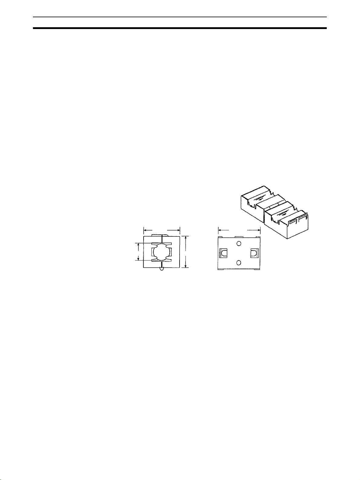
The following examples show means of reducing noise.
1,2,3... 1. Noise from the communications cable can be reduced by installing a ferrite
core on the communications cable within 10 cm of the DeviceNet PCI
Board.
Ferrite Core (Data Line Filter): 0443-164151 (manufactured by Nisshin Electric Co.)
Impedance Specifications
25 MHz: 156 Ω
100 MHz: 250 Ω
7 Components
33 mm
13 mm
30 mm
29 mm
2. Keep DeviceNet communications cables as short as possible and ground
to 100
Ω min.
Be sure that you have received the following components.
• One PCI Board (with communications connector)
• One installation disk (CD-ROM) for Scanner SDK
• One operation manual (this manual)
• One User Registration Card (which also serves as the software usage
license agreement)
xviii
Page 18

SECTION 1
Introduction
This section provides an overview of the DeviceNet Scanner SDK functions, specifications, and system configurations.
1-1 Product Configuration . . . . . . . . . . . . . . . . . . . . . . . . . . . . . . . . . . . . . . . . . . . 2
1-2 DeviceNet PCI Board . . . . . . . . . . . . . . . . . . . . . . . . . . . . . . . . . . . . . . . . . . . 2
1-3 Scanner SDK Functions and Features . . . . . . . . . . . . . . . . . . . . . . . . . . . . . . . 3
1-4 Scanner SDK Functions. . . . . . . . . . . . . . . . . . . . . . . . . . . . . . . . . . . . . . . . . . 4
1-4-1 I/O Communications . . . . . . . . . . . . . . . . . . . . . . . . . . . . . . . . . . . . . 4
1-4-2 Message Communications Function . . . . . . . . . . . . . . . . . . . . . . . . . 5
1-4-3 Maintenance Functions . . . . . . . . . . . . . . . . . . . . . . . . . . . . . . . . . . . 6
1-5 System Configuration . . . . . . . . . . . . . . . . . . . . . . . . . . . . . . . . . . . . . . . . . . . 7
1-6 Specifications. . . . . . . . . . . . . . . . . . . . . . . . . . . . . . . . . . . . . . . . . . . . . . . . . . 8
1-6-1 DeviceNet PCI Board General Specifications . . . . . . . . . . . . . . . . . 8
1-6-2 DeviceNet Communications Specifications . . . . . . . . . . . . . . . . . . . 8
1-6-3 Scanner SDK Communications Specifications. . . . . . . . . . . . . . . . . 9
1-6-4 Development Environment . . . . . . . . . . . . . . . . . . . . . . . . . . . . . . . . 9
1-6-5 Dimensions . . . . . . . . . . . . . . . . . . . . . . . . . . . . . . . . . . . . . . . . . . . . 10
1-7 Board Components . . . . . . . . . . . . . . . . . . . . . . . . . . . . . . . . . . . . . . . . . . . . . 10
1-8 Preparation for Operation . . . . . . . . . . . . . . . . . . . . . . . . . . . . . . . . . . . . . . . . 11
1
Page 19
Product Configuration Section 1-1
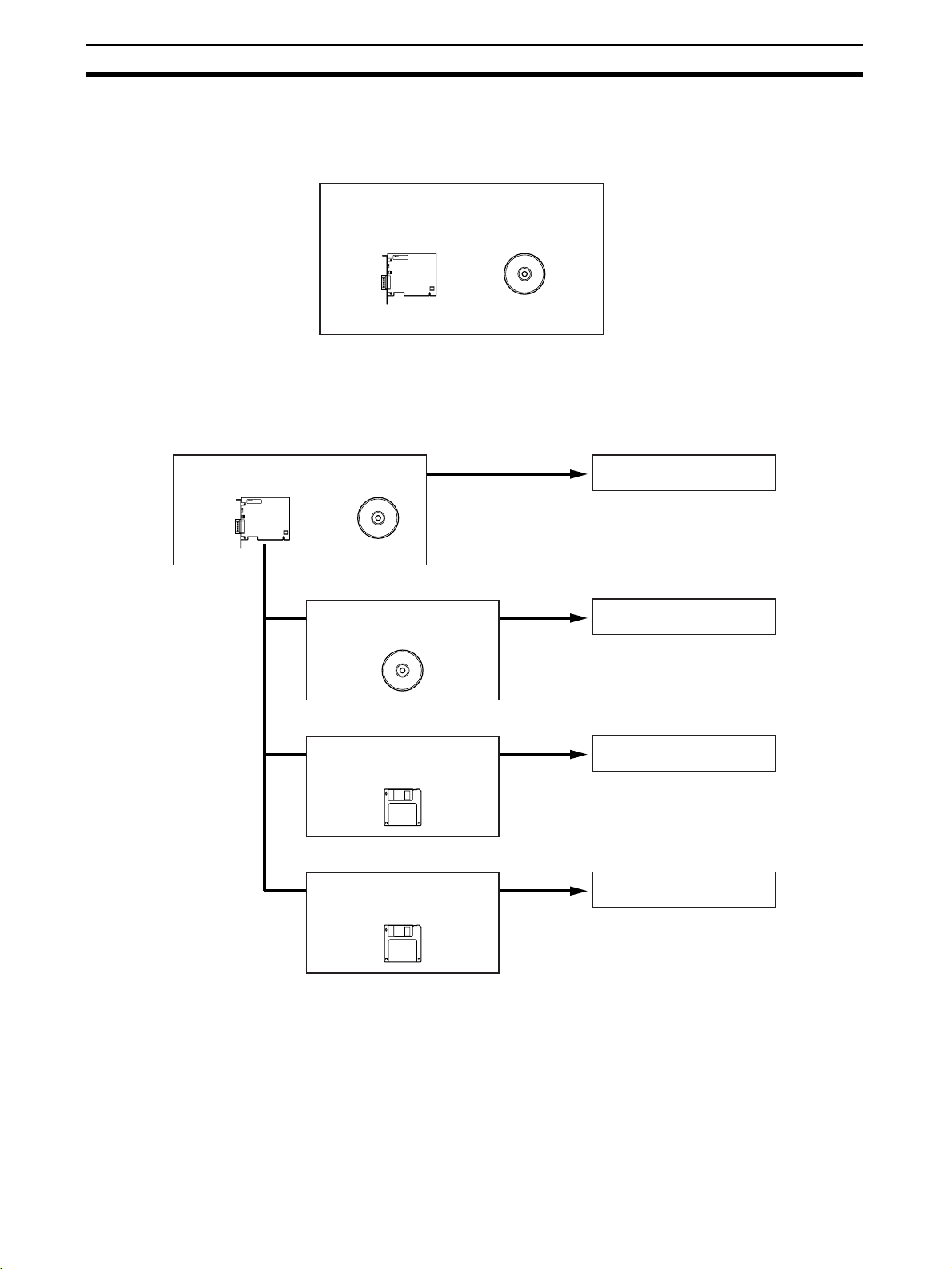
1-1 Product Configuration
The 3G8F7-DRM21-E DeviceNet PCI Board includes the PCI Board (hardware) and the Scanner SDK software on CD-ROM.
3G8F7-DRM21-E DeviceNet PCI Board Scanner
PCI Board Scanner SDK
1-2 DeviceNet PCI Board
The PCI Board is used as an interface to other software, such as the
DeviceNet Configurator, NetXServer, and Analyzer.
DeviceNet PCI Board Scanner
WS02-CFDC1-E DeviceNet
Configurator
WS02-NXD@-1 NetXServer
for DeviceNet
WS02-ALDF-E DeviceNet
Analyzer
DeviceNet Scanner SDK
DeviceNet Configurator
NetXServer for DeviceNet
DeviceNet Analyzer
DeviceNet Scanner SDK The DeviceNet Scanner SDK (this product) is a library for developing applica-
tions that operate as DeviceNet Masters or Slaves. It is supplied as a DLL file
for a Windows environment.
Use the Scanner SDK to develop Master/Slave applications with industryleading performance and functions.
2
Page 20

Scanner SDK Functions and Features Section 1-3
DeviceNet Configurator The DeviceNet Configurator is a Windows-based application that supports
construction of DeviceNet networks. The Configurator is used not only for setting parameters and monitoring OMRON Master and Slave devices, but also
for setting parameters for slaves from other manufacturers, simply by installing
the EDS files.
The Configurator provides extensive support for managing networks, from
design through to maintenance.
NetXServer for DeviceNet The NetXServer is middleware that operates in a Windows environment. The
NetXServer collects I/O data from a DeviceNet network and provides it to
monitoring and other applications. It operates as a DDE server.
NetXServer enables I/O data monitoring without affecting Master or Slave
communications.
The following two types of NetXServer are available:
DDE Edition: For monitoring I/O data using a DDE client (e.g., Microsoft
Excel)
SDK Edition: Library for developing monitoring applications using NetXServer
functions
DeviceNet Analyzer The DeviceNet Analyzer is a Windows-based application for analyzing mes-
sage frames on a DeviceNet network.
The DeviceNet Analyzer can display the message frames being transmitted
on a network and indicate traffic status. It can be used to find the source of
errors and for developing DeviceNet-compatible devices.
1-3 Scanner SDK Functions and Features
DeviceNet
Communications
Functions
Note The DeviceNet network is capable of exchanging I/O with distant Slaves
DeviceNet
Communications Features
The Scanner SDK is equipped with the following communications functions.
• I/O communications functions that exchange I/O data with other
DeviceNet nodes:
DeviceNet Master function
DeviceNet Slave function
• DeviceNet explicit messaging functions (client and server functions)
In addition to the communications functions above, the Scanner SDK has a
status function that reads the status of the node (Master/Slave) and the network and an error log function that records errors and their time of occurrence.
through a single cable. Moreover, Slaves and other Masters can be controlled
and monitored by sending and receiving explicit messages. Refer to the
DeviceNet Operation Manual (W267) for more details.
In this manual, the “client” is the node that sends a message requesting services and the “server” is the node that receives the message, performs the
requested processing, and returns a response.
The Scanner SDK has the following features:
Exchange I/O Data with DeviceNet Slaves
The status of I/O points on DeviceNet Slaves is mirrored in the DeviceNet PCI
Board. I/O can be performed with a specified Slave by calling the functions for
reading and writing I/O data.
3
Page 21
Scanner SDK Functions Section 1-4
Use Other Vendor’s DeviceNet-compatible Devices
DeviceNet is a worldwide standard, so any manufacturer’s Slave can be connected as long as it is DeviceNet compatible.
I/O Capacity of 37,800 Bytes for Up To 63 Slaves
The Scanner SDK provides 37,800 bytes for I/O allocation to up to 63 Slaves
(input: 25,200 bytes; output: 12,600 bytes).
Use API Functions to Control Devices
All Scanner SDK functions are provided as API functions. User applications
are created using the API functions.
Check Events with Windows Messaging or Polling
Events can be checked in two ways: automatic notification by Windows messaging and monitoring (polling) of the Board’s event queue by user applications. Use the method most appropriate for each application.
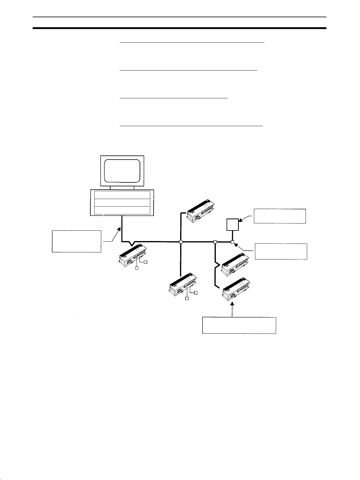
Computer
Application program
API functions
One-cable, reduced
wiring
Max. network length
of 500 m
Output Slave
PCI Board
DeviceNet
communications
cable
T-branch Tap
Relay
Solenoid
Other company's Slaves
can be connected.
T-branching and multidrop wiring can be
combined freely.
Input Slave
Switch
Sensor
Connect up to 63 DeviceNet
Slaves.
1-4 Scanner SDK Functions
1-4-1 I/O Communications
Master Function The Scanner SDK Master function provides two 200-byte input areas (100
words or 1,600 points) and one 200-byte output area (100 words or 1,600
points) for allocation to each slave.
I/O communications are executed according to the scan list registered by the
Scanner SDK. Scan lists record information such as the number of input and
output bytes for each slave.
4
Page 22

Scanner SDK Functions Section 1-4
Maximum Numbers of I/O Points and Slaves
The following table shows the max. number of I/O points, max. number of
Slaves, and max. number of I/O connections allowed by the Scanner SDK’s
Master function.
Item Specification
Max. number of I/O
points
Max. number of I/O
points per Slave
Max. number of Slaves 63 Slaves (Node addresses 0 to 63 can be used.)
Max. number of I/O connections per Slave
Note Two input areas have been provided for each slave, but normally only the first
area is used. If two connections are used at the same time, then the second
input area can be used.
Slave Function The Scanner SDK Slave function provides two 200-byte input areas (100
words or 1,600 bits) and one 200-byte of output area (100 words or 1,600
bits). The following methods can be used to register the Master in the slave
scan list.
1,2,3... 1. Use functions to register Masters individually or in a group.
2. Register Masters in a group by specifying a parameter file that was created
with the OMRON DeviceNet Configurator.
A slave scan list must be registered in the Scanner SDK for nodes to operate
as Slaves.
Input: 25,200 bytes (= 12,600 words or 201,600 points)
Output: 12,600 bytes (= 6,300 words or 100,800 points)
Input: 200 bytes × 2 (= 100 words × 2 or 1,600 points × 2)
Output: 200 bytes (= 100 words or 1,600 points)
2 max.
Maximum Numbers of I/O Points and Masters
The following table shows the max. number of I/O points and max. number of
Masters allowed by the Scanner SDK’s Slave function.
Item Specification
Max. number of I/O points Input: 200 bytes × 2 (= 100 words × 2 or 1,600 points × 2)
Output: 200 bytes (= 100 words or 1,600 points)
Max. number of Masters 1 Master
Note Two input areas have been provided, but normally only the first area is used. If
two connections are used at the same time, then the second input area can
be used.
1-4-2 Message Communications Function
Explicit Message
Communications
The DeviceNet PCI Board supports explicit message communications.
As a client, the DeviceNet PCI Board can send explicit messages to control or
monitor other nodes in the DeviceNet network when necessary.
As a server, the DeviceNet PCI Board can receive explicit messages from
other nodes. (The requested processing and responses must be handled in
user applications.)
Explicit message communications can be used to freely communicate with
DeviceNet-compatible devices produced by other companies.
5
Page 23

Scanner SDK Functions Section 1-4
Maximum Number of
Connections
The following table shows maximum number of connections allowed.
Item Specification
Max. number of client connections
Max. number of server connections
63 connections (1 connection per server)
4 connections (1 connection per client)
1-4-3 Maintenance Functions
Read Status Functions The DeviceNet PCI Board can read the following information, including set-
tings and the operating status of the nodes (Master/Slaves) and network.
• Scanner SDK’s DLL version
• DeviceNet PCI Board’s driver version
• Whether or not the DeviceNet PCI Board is installed
• Network status
• Operational status in the network/status in remote I/O communications
• Communications status
• Whether or not each Slave is registered in the scan list
• Each Slave’s device status
Reset Function The DeviceNet PCI Board can be reset (initialized) with a command from the
computer.
Communications Cycle
Time Management
This function can set the communications cycle time (interval between the
exchange of the Slave’s I/O) and read or clear the minimum and maximum
values.
Error Log The DeviceNet PCI Board has an error log function that records information
on errors that occur during operation. The error log can be checked to pinpoint errors for faster error processing and recovery.
PC Watchdog Timer
Management
Remote I/O can be made to stop automatically if the application that controls
the DeviceNet PCI Board stops for some reason. The Board’s PC watchdog
timer is refreshed regularly from the computer (application) to notify the Board
that the application is operating normally.
6
Page 24
System Configuration Section 1-5
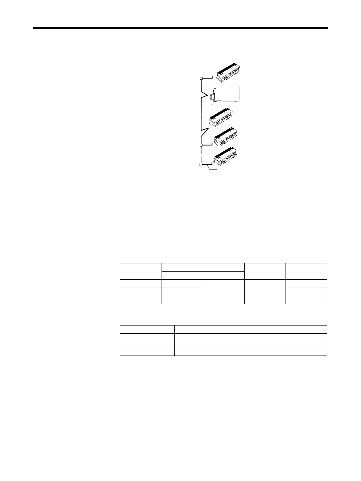
1-5 System Configuration
The following diagram shows the various device connections allowed.
Trunk line
(A cable with terminators
connected on both ends.)
DeviceNet Cable
Slave connected by
the multi-drop method
Slave connected by the T-branch
method using a T-branch Tap
T-branch Tap with
terminator installed
PCI
Board
Drop line
(A cable branching from the
trunk line, 6 m max.)
Input Slave
Output Slave
Output Slave
Input Slave
Note Refer to the following manuals for information on Slaves.
• DRT2 Series DeviceNet Slave Operation Manual (W404)
• C200HW-DRT21, CQM1-DRT21, and DRT1 Series DeviceNet Slave
Operation Manual (W347)
• DRT1-COM and GT1 Series DeviceNet MULTIPLE I/O TERMINAL Operation Manual (W348)
Baud Rate and Distance The following table shows the relationship between the baud rate and commu-
nications distance in the DeviceNet network.
Slave Connection
Methods
Baud rate Maximum network length Drop line
Thick cable Thin cable
500 kbps 100 m max. 100 m max. 6 m max. 39 m max.
250 kbps 250 m max. 78 m max.
125 kbps 500 m max. 156 m max.
length
Slave devices can be connected in two ways. These connection methods can
be combined in the same network.
Method Description
T-branch Method Slaves are connected to a drop line from the trunk line or
branch line created with a T-branch Tap.
Multi-drop Method Slaves are directly connected to the trunk line or the drop line.
Total drop line
length
Note Refer to the DeviceNet Operation Manual (W267) for details on connection
methods and grounding.
7
Page 25

Specifications Section 1-6
1-6 Specifications
1-6-1 DeviceNet PCI Board General Specifications
Item Specifications
Dimensions 119.9 × 106.7 mm (W × H)
Operating voltage range 5 VDC ± 5% (3.3 VDC is not used.)
Current consumption Internal power supply: 290 mA max. at 5 VDC
Vibration resistance
Shock resistance
Ambient temperature Operating: 0 to 55°C
Humidity 10% to 90% (with no condensation)
Atmosphere Must be free from corrosive gas
Weight 91 g max.
Max. number of Boards 3 Boards/computer max.
Communications power supply: 30 mA max. at 24 VDC
2
10 to 57 Hz, 0.075-mm double amplitude, 57 to 150 Hz, acceleration: 9.8 m/s
directions for 80 minutes each (Time coefficient; 8 minutes × coefficient factor 10 = total time
80 minutes)
DIN Track installation: 2 to 55 Hz, 2.94 m/s2 in X, Y, and Z directions for 20 minutes each
147 m/s2 three times each in X, Y, and Z directions
Storage: –20 to 60°C
in X, Y, and Z
The DeviceNet PCI Board conforms to PCI Local Bus Specification Rev. 2.
1-6-2 DeviceNet Communications Specifications
Item Specification
Communications protocol DeviceNet
Connection forms Multi-drop and T-branch connections can be used for trunk or drop lines.
Terminators must be connected at both ends of the trunk line.
Baud rate 500 kbps, 250 kbps, or 125 kbps (Specified with the SCAN_Online function.)
Communications media Special 5-wire cables (2 signal lines, 2 power lines, 1 shield line)
Communications distances
Communications power supply 11 to 24 VDC, 30 mA (supplied through the communications connector)
Max. number of Slaves 63 Slaves
Communications cycle time (see
note 2)
Error control checks CRC error check, node address duplication check, scan list verification
Cable 5 conductors (two signal wires, two power supply wires, and one shield wire)
500 kbps Network length: 100 m max.
Drop line length: 6 m max.
Total drop line length: 39 m max.
250 kbps Network length: 250 m max. (see note 1)
Drop line length: 6 m max.
Total drop line length: 78 m max.
125 kbps Network length: 500 m max. (see note 1)
Drop line length: 6 m max.
Total drop line length: 156 m max.
Set between 1 and 500 ms with the SCAN_SetScanTimeValue() function.
Note Indicates the max. length when thick cables are used. Reduce the network
length to 100 m max. when using thin cables. When using both thick and thin
cables together, refer to the DeviceNet Operation Manual (W267) for details
on the maximum network length.
8
Page 26

Specifications Section 1-6
1-6-3 Scanner SDK Communications Specifications
Item Specifications
Supported I/O connections • Bit Strobe
• Polling
•Cyclic
• Change of State (COS)
• Explicit Peer-to-peer Messaging
Communications cycle time (See note.) 2 to 500 ms (Can be specified using API functions.)
Number of server nodes capable of simultaneous
communications as explicit clients
Number of client nodes capable of simultaneous
communications as explicit servers
Data length for explicit messages Client:
Response monitoring time for explicit messages (for
clients)
Retries for explicit messages 0 (Retries must be performed by the user application.)
63 nodes
4 nodes
Explicit message request: 552 bytes
Explicit message response: 552 bytes
Server:
Explicit message request: 552 bytes
Explicit message response: 552 bytes
2 s (default) (Can be specified using API functions.)
Note The communications cycle time is the maximum time from when remote I/O
communications are executed by the Master to a Slave until remote I/O communications are executed again for the same Slave.
Minimum System
Requirements
Hardware Requirements
IBM PC/AT or Compatible
• At least one PCI bus slot (PCI bus Rev. 2.0 or later)
• 5 MB min. free hard disk space
(plus additional space for the user program)
• One CD-ROM drive is required to install the software.
• VGA or better display functions.
The processor, memory capacity, and other specifications not listed above
should conform to the recommendations for the operating system used.
OS
Microsoft Windows 95, 98, Me, NT 4.0, 2000, or XP.
Windows 3.1 and Windows NT 3.5 are not supported.
1-6-4 Development Environment
Recommended
Development Environment
Other Development
Environments
Microsoft Visual C++ (Ver. 6.0 or later.)
• Microsoft Visual Basic
Some functions are limited. Refer to Precautions when Using Other
Development Environments under 3-1 Application Development Environments for details.
• Borland C++ Builder
Refer to Refer to Precautions when Using Other Development Environ-
ments under 3-1 Application Development Environments for details.
9
Page 27
Board Components Section 1-7
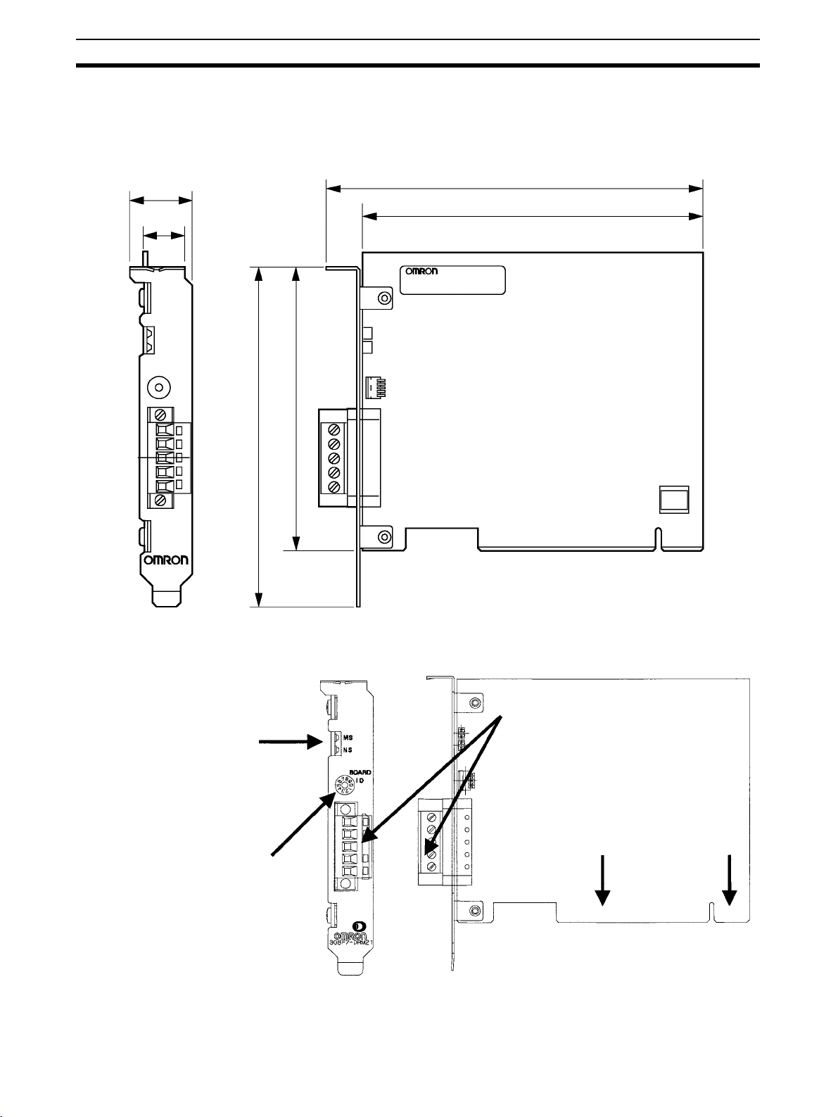
1-6-5 Dimensions
The following diagram shows the dimensions of the DeviceNet PCI Board.
(The height of components on the Board is within specifications for a single
PCI slot.)
21.6 mm
14.7 mm
106.7 mm
126.4 mm
132.3 mm
119.9 mm
1-7 Board Components
LED indicators (MS and NS)
These are the DeviceNet MS
(module status) and NS (network status) indicators.
Board ID switch
When two or more DeviceNet PCI
Boards are installed in a computer,
the computer uses the board ID
settings to distinguish the Boards
from each other. Set unique decimal board IDs between 0 and 7.
(The height of the component surface
will fit in one PCI bus slot.)
Communications connector
Connects the Board to the DeviceNet
communications cable.
PCI interface
Connects the Board to the
computer's PCI slot.
10
Page 28

Preparation for Operation Section 1-8
LED Indicators The following table explains the operation of the LED indicators.
Indicator status Meaning
MS NS
OFF OFF Boot program initialization is in progress.
Flashing green OFF Scanner firmware initialization is in progress.
Lit green OFF Waiting for online request.
Lit green Flashing green A connection was established and I/O communi-
cations are in progress.
Waiting for a connection from the Master.
Lit green Lit green I/O communications or message communications
Board ID When two or more DeviceNet PCI Boards are installed in a computer, the
computer uses the board ID settings to distinguish the Boards from each
other. Specify the board ID in API functions to identify the desired board.
Set the board ID in decimal as shown in the following diagram. The allowed
setting range is 0 to 7. (The factory setting is 0.)
Up to 3 DeviceNet PCI Boards can be installed in one computer.
are in progress.
Note Any board ID from 0 to 7 can be set, as long as the ID is not set on another
DeviceNet PCI Board in the computer. (It is physically possible to set board
IDs 8 and 9, but the Board cannot be used properly with these settings.)
1-8 Preparation for Operation
Hardware Settings If more than one DeviceNet PCI Board is being installed in one computer, set
the board IDs on the Boards’ rotary switches so that the different Boards can
be distinguished from one another. Refer to 2-2 Installing the Board in the
Computer for details.
Always set the rotary switches before turning ON the computer.
Installation on Computer Install the Board in the computer. Refer to 2-2 Installing the Board in the Com-
puter for details.
Software Installation Install the DeviceNet PCI Board driver and software required to use the Board
from the computer. Refer to 2-3 Installing the Drivers and 2-4 Installing the
Scanner SDK Software for details.
Writing the Program Write the programs (user applications) that make software settings and con-
trol the Board. Refer to SECTION 3 Using API Functions through SECTION 7
Error Processing for details.
Reference Information Refer to 2-5 DeviceNet Connections for information on communications cable
connections.
Refer to the DeviceNet Operation Manual (W267) for information on wiring
DeviceNet networks.
Refer to the DeviceNet Slave Operation Manuals (W404 and W347) and the
DeviceNet MULTIPLE I/O TERMINAL Operation Manual (W348) for information on Slaves.
11
Page 29

Preparation for Operation Section 1-8
12
Page 30

SECTION 2
Software Installation
This section explains how to install the DeviceNet PCI Board in a computer, how to install the software, and how to connect
the communications cables.
2-1 Installation Procedure . . . . . . . . . . . . . . . . . . . . . . . . . . . . . . . . . . . . . . . . . . . 14
2-2 Installing the Board in the Computer. . . . . . . . . . . . . . . . . . . . . . . . . . . . . . . . 14
2-3 Installing the Drivers . . . . . . . . . . . . . . . . . . . . . . . . . . . . . . . . . . . . . . . . . . . . 16
2-4 Installing the Scanner SDK Software . . . . . . . . . . . . . . . . . . . . . . . . . . . . . . . 23
2-5 DeviceNet Connections . . . . . . . . . . . . . . . . . . . . . . . . . . . . . . . . . . . . . . . . . . 29
2-5-1 Attaching Connectors to the DeviceNet Cable . . . . . . . . . . . . . . . . . 29
2-5-2 Connecting Communications Cables . . . . . . . . . . . . . . . . . . . . . . . . 31
13
Page 31

Installation Procedure Section 2-1
2-1 Installation Procedure
There procedure for installing the DeviceNet PCI Board and its software is
outlined below.
Installing the Board in the Computer
Set the board ID (rotary switch) and install
the Board in the computer.
Windows 95, 98, Me, 2000, XP
Installing the Driver
Install the DeviceNet PCI Board driver.
Installing the Scanner SDK Software
Install the provided Scanner SDK
software.
Note For Windows 2000 or XP, you must log in with administrator rights to install the
driver and Scanner SDK Software.
2-2 Installing the Board in the Computer
This section explains how to make the required settings on the DeviceNet PCI
Board and install the Board in the computer.
Preparation for
Installation
The DeviceNet PCI Board is plug-and-play compatible with MicroSoft Windows. Check the following points before installing the Board.
Check point Description
Available PCI slot Make sure that the computer has an available PCI slot.
IRQ conflict The DeviceNet PCI Board uses an IRQ.
IRQ settings are allocated automatically to the PCI bus, but
not to the ISA bus. In computers with ISA slots, the computer
may not boot completely if there is an IRQ conflict with the ISA
bus. In this case, make one of the following changes in the
BIOS settings:
• Enter the BIOS setup and specify a non plug-and-play (PnP)
operating system.
• Enter the BIOS setup and reserve the IRQ numbers (disable
automatic allocation of these IRQ numbers) that are used by
the ISA bus so that these IRQ numbers will not be allocated
automatically to the PCI bus.
Refer to the computer’s User’s Guide for details on entering
the BIOS setup and changing the settings. (See note below
for details on identifying IRQ numbers.)
Windows NT 4.0
14
Note Use the following procedure to identify which IRQ numbers are being used by
the ISA bus.
1,2,3... 1. Start the computer without the DeviceNet PCI Board installed.
2. Start the Device Manager (Control Panel/System/Device Manager).
3. Open the properties of the relevant devices and check their IRQ (Interrupt
Request) settings in the Resources tab.
Page 32

Installing the Board in the Computer Section 2-2
Board ID Setting Set the board ID on the DeviceNet PCI Board’s rotary switch before installing
the board.
Note Static electricity can damage the DeviceNet PCI Board’s electronic
components. Do not touch the Board’s connector or components.
Set a board ID between 0 and 7. If two or more DeviceNet PCI Boards are
being installed in the computer, be sure that each Board has a unique board
ID setting. The factory setting is 0.
Installing the Board in the
Computer
Note (1) Turn OFF the computer power supply before installing the DeviceNet PCI
1,2,3... 1. Disconnect all cables from the DeviceNet PCI Board.
Install the DeviceNet PCI Board in one of the computer’s PCI slots.
Refer to your computer’s User’s Guide for details on installing a PCI card in
the computer.
Board.
(2) Take precautions against static electricity.
2. Turn OFF the computer in which the board is being installed and unplug
the computer’s power cord.
3. Remove the computer’s case and make any other preparations needed to
install a PCI board. (Refer to your computer’s User’s Guide for details.)
4. Align the Board with the computer’s PCI slot, slide it into position, and
press it firmly into the slot. Check that the Board’s PCI interface is completely and evenly installed into the PCI slot. Do not use much force when
pressing the board; it should slide into the slot with little resistance.
(a)
(b)
5. Pull on the Board lightly to check that it is installed securely and won’t slip
out.
6. Secure the Board by tightening the retaining screw, indicated by (b) in the
diagram, to 0.5 N
7. Attach the case to the computer and turn ON the power.
8. The installation method differs depending on the type of Windows operating system used. Refer to the following during installation.
• Windows 95, 98, Me, 2000, or XP
After the computer is started, the Board will be detected as new hardware
and the InstallShield Wizard will start. Refer to 2-3 Installing the Drivers
for the rest of the installation procedure.
• Windows NT 4.0
The PCI Board will not be recognised when the computer is started.
Install the driver for the PCI Board at the same time as Scanner SDK.
Refer to 2-4 Installing the Scanner SDK Software for the rest of the installation procedure.
⋅m.
15
Page 33

Installing the Drivers Section 2-3
2-3 Installing the Drivers
After the Board is installed in the computer and the computer is started, the
Board will be detected as new hardware (except for Windows NT computers,
see note). Install the driver to ensure correct operation of the Board.
The installation method and windows displayed when installing the driver will
differ depending on the Windows operating system used.
This section describes driver installation for Windows 98 and XP.
Note The Board will not be automatically detected with Windows NT 4.0.
The driver must be installed with Scanner SDK. Perform the installation procedure described in 2-4 Installing the Scanner SDK Soft-
ware.
Windows 98 Installation
1,2,3... 1. After the Board is installed in the computer and the computer is started, the
Board will be detected as new hardware and the Add New Hardware Wizard will start automatically as shown in the following diagram.
Click the Next Button.
16
2. A window will be displayed to select the driver search method. Select Display a list of all ... and click the Next Button.
Page 34

Installing the Drivers Section 2-3
3. Select Other devices as the device type and click the Next Button.
4. Click the Have Disk Button to specify the hardware model.
17
Page 35

Installing the Drivers Section 2-3
5. Insert the Scanner SDK CD-ROM disk in the CD-ROM drive.
6. Specify the CD-ROM drive’s Win98 directory as the source location and
click the OK Button.
(You can click the Browse Button to display a list of the actual directories
and select the Win98 directory from that list. The following example window shows the CD-ROM drive as drive A.)
18
7. When the driver information has been read from the CD-ROM, select
OMRON 3G8F7-DRM21-E PCI Adapter as shown in the following diagram.
Click the Next Button.
Page 36

Installing the Drivers Section 2-3
8. Check the displayed message and click the Next Button if the correct driver is displayed. The drivers will be installed.
9. A completion message will be displayed when installation of the Windows
98 drivers is completed. Click the Finish Button to complete the installation.
19
Page 37

Installing the Drivers Section 2-3
Windows XP Installation
Note You must login to Windows XP with Administrator rights to install the driver.
1,2,3... 1. After the Board is installed in the computer and the computer is started, the
Board will be detected as new hardware and the Found New Hardware
Wizard will start automatically as shown in the following diagram. Select In-
stall from a list or specific location (Advanced), as shown in the following
diagram, and then click the Next Button.
20
2. Insert the Scanner SDK CD-ROM into the CD-ROM drive.
Page 38

Installing the Drivers Section 2-3
3. Select Search for the best driver in these locations for the search and install option, and select the Include this location in the search option.
Click the Browse Button, specify the CD-ROM drive’s Win2000 folder (see
following diagram), and then click the Next Button.
Note In this example, the CD-ROM drive is drive F.
4. The driver installation will start.
21
Page 39

Installing the Drivers Section 2-3
5. The following window will be displayed during installation, but it does not
indicate an error. Click the Continue Button to continue the installation.
6. A completion message will be displayed when installation of the driver has
been completed (see diagram.) Click the Finish Button to complete the installation procedure.
22
Page 40

Installing the Scanner SDK Software Section 2-4
2-4 Installing the Scanner SDK Software
This section explains how to install the Scanner SDK’s software.
Note The operations and windows will vary slightly depending upon the
version of Windows being used. Windows XP is used in this example.
With Windows 2000 or XP, you must log in with Administrator rights
to install the Scanner SDK Software.
Installation Procedure
1,2,3... 1. Close all applications that are being executed.
2. Insert the Scanner SDK’s CD-ROM disk in the CD-ROM drive.
3. Click the Windows Start Button and select Run.
4. Input a:\setup in the displayed input field. (In this case the system disk is
in drive F.)
5. Click the OK Button to begin the software installation.
6. Installation of the software will begin and the InstallShield Wizard will begin
preparations.
23
Page 41

Installing the Scanner SDK Software Section 2-4
7. When the setup window is displayed, click the Next Button to continue.
24
8. The software usage license agreement will be displayed.
Read all of the conditions in the agreement and click the Ye s Button if you
agree.
Click the No Button if you do not agree.
Note Installation will stop if the No Button is clicked.
Page 42

Installing the Scanner SDK Software Section 2-4
9. Select the destination folder for the installation.
The following folder is the default destination:
C:\Program Files\OMRON\DeviceNet Scanner SDK
To change the destination folder, click the Browse Button and specify the
desired folder. (If a non-existent folder is specified, a new folder with that
name will be created automatically.)
Click the Next Button after specifying the desired directory.
A window will be displayed to specify the program folder for the Start menu.
25
Page 43

Installing the Scanner SDK Software Section 2-4
10. Specify the program folder that contains as the DeviceNet Scanner SDK
shortcuts in the Windows Start menu.
A shortcut to the DeviceNet Scanner SDK folder is created by default:
Start/Programs/DeviceNet Tools/DeviceNet Scanner SDK
To change the default folder, select an existing folder or input a new folder
name. (If a non-existent folder is specified, a new folder with that name will
be created automatically.)
Click the Next Button after specifying the desired program folder. The installation will begin and the files will be copied. The progress of the installation will be displayed as the installation proceeds.
11. A completion message will be displayed when the installation is completed. Click the OK Button to complete the installation.
26
Page 44

Installing the Scanner SDK Software Section 2-4
Installed Files When the Scanner SDK is installed, the following folders are created and the
required files are installed.
The following table shows the folders and files that are created and installed
when the default folders are used.:
Default Folder Contents
Removing the DeviceNet
Scanner SDK Software
\Program Files\OMRON\DeviceNet Scanner
SDK\Manual\
\Program Files\OMRON\DeviceNet Scanner
SDK\Program\
\Program Files\OMRON\DeviceNet Scanner
SDK\SDK\Include\
\Program Files\OMRON\DeviceNet Scanner
SDK\SDK\Lib\
\Program Files\OMRON\DeviceNet Scanner
SDK\SDK\Sample\
If the DeviceNet Scanner SDK Software is no longer needed, the files and
other information can be removed with the following procedure. (Only the
The PDF file of this manual is
installed.
Execution files for the sample program are installed.
A sample Include file is installed.
The library files used for static links in
Microsoft Visual C++ are installed.
A sample program is installed.
installed files and information will be removed. Files created later will not be
removed.)
1,2,3... 1. Select Start/Settings/Control Panel from the Windows Start Button.
2. Double-click the Add/Remove Programs Icon in the Control Panel.
3. Select DeviceNet Scanner SDK from the list. Click the Add/Remove Button.
27
Page 45

Installing the Scanner SDK Software Section 2-4
4. A confirmation message will be displayed. Click the OK Button to proceed.
5. Removal of the application will start.
28
6. During removal, messages asking if detected shared files are to be deleted
may be displayed (see diagram below).
• If other DeviceNet applications, such as the Configurator, NetXServer, or
Analyzer, are installed, click the No Button. Do not delete the shared files.
Page 46

DeviceNet Connections Section 2-5
• If no other DeviceNet applications are installed, click the Yes Button. The
shared files can be deleted.
7. A completion message will be displayed when removal of the driver has
been completed (see diagram.) Click the Finish Button to complete the installation procedure.
2-5 DeviceNet Connections
Connect the DeviceNet communications cables after installing the Board.
This section explains how to prepare and connect the communications cables
to the DeviceNet PCI Board only. Refer to the DeviceNet Operation Manual
(W267) for details on connecting cables to Slaves.
2-5-1 Attaching Connectors to the DeviceNet Cable
This section explains how to attach connectors to the network communications cables. Use the following procedures prepare the communications
cables and attach connectors.
29
Page 47

DeviceNet Connections Section 2-5
1,2,3... 1. Remove about 30 mm of the cable sheathing, being careful not to damage
the woven shielding underneath. Do not remove too much sheathing; removing too much of the sheathing can result in short circuits and increase
the effect of noise.
Approx. 30 mm
2. Carefully peel back the woven shielding. The cable contains a shielding
wire along with the signal lines and power lines. The shielding wire is stiffer
than the woven shielding, so it can be identified by touch.
Shielding wire
3. Remove the exposed woven shielding, remove the aluminum tape from the
signal and power lines, and strip the covering from the signal and power
lines to the proper length for the crimp terminal connectors being used.
Twist the wire strands on each of the signal and power lines so that there
are no loose strands.
Strip to match the crimp terminals
4. Attach the crimp terminals (solderless pin terminals) to the lines and use
the proper Crimping Tool to crimp the terminal securely.
Crimp terminal
Note We recommend using the following crimp terminals and crimping tools.
• NICHIFU TC-series Crimp Terminals
Cable type XW4B-05C10H1-D
Using thin
cable
Using thick
cable
XW4B-05C10V1R0D
MSTB2.5/5-ST5.08AU
XW4B-05C4-TF-D
XW4B-05C4-T-D
Communications lines
Power lines TMEV TC-0.3-9.5 TGN TC-1.25-9T
Communications lines
Power lines TMEV TC-2-11
TMEV TC-0.3-9.5 TGN TC-1.25-9T NH-32
TMEV TC-1.25-11 Not compatible
XW4G-05C1-H1-D
XW4G-05C4-TF
Crimping
Too l
30
Page 48

DeviceNet Connections Section 2-5
• PHOENIX CONTACT, AI-series Crimp Terminals
Cable type XW4B-
Using thin
cables
Using thick
cables
Signal lines AI0.25-6BU AI0.25-8YE AI0.25-8YE CRIMPFOX
Power lines AI0.5-6WH AI0.5-10WH AI0.5-10WH
Signal lines AI 2.5-8BU AI 2.5-8BU AI 2.5-12BU
Power lines AI 2.5-8BU AI 2.5-8BU AI 2.5-12BU
05C10H1-D
XW4B-
05C10V1R0D
MSTB2.5/5-
ST-5.08AU
5. Cover the end of the cable with electrical tape or heat-shrink tubing as
shown in the following diagram.
Electrical tape or
heat-shrink tubing
XW4B-
05C4-TF-D
XW4B-
05C4-T-D
XW4G-
05C1-H1-D
XW4G-
05C4-TF
Crimping
Too l
UD6
2-5-2 Connecting Communications Cables
1,2,3... 1. Remove the connector from the Board’s DeviceNet Communications Con-
nector. (It isn’t necessary to remove the connector from the Board if it can
be wired in place.)
2. Orient the connector properly and then insert the lines in order from left to
right: black, blue, shield, white, and then red.
Blue (CAN low)
Black (-V)
Red (+V)
White (CAN high)
Shield
Note (1) Loosen the screws for securing the connector wires before inserting sig-
nal lines, power lines, or the shield wire. If the screws are not loosened
sufficiently, the wires cannot be inserted into the correct position. They
will enter the gap at the back where they cannot be secured in place.
(2) The connector and Board have colored stickers that match the wire col-
ors. The wire colors can be checked against the sticker color to check that
the cables are wired correctly.
31
Page 49

DeviceNet Connections Section 2-5
(3) The wire colors are listed in the following table.
Color Signal Symbol
Black Communications power supply (negative) V−
Blue Signal LOW side CAN L
--- Shield S
White Signal HIGH side CAN H
Red Communications power supply (positive) V+
3. Tighten the line set screws for each line in the connector. Tighten the
screws to a torque between 0.25 and 0.3 N
You will not be able to tighten these screws with a normal screwdriver,
which tapers at the end. You will need a screwdriver that does not taper at
the end, such as a large precision screwdriver.
When using a Thick Cable, allow sufficient cable to ensure that the tension
of the cable does not disconnect the connector.
Use a flat-blade screwdriver
that does not taper at the end.
⋅m.
Note The following diagram shows the dimensions of the OMRON
XW4Z-00C screwdriver, which is ideal for these DeviceNet connectors.
Side Front
0.6 mm 3.5 mm
4. Align the connector to the Board’s Connector and then insert the connector
until it is securely set in place. Firmly tighten the screws at both ends of the
connector. Tighten the connector mounting screws to a torque between
0.25 and 0.3 N
⋅m.
32
Page 50

DeviceNet Connections Section 2-5
Standard Connector (Thin Cables Only)
When thin cable is being used, a multi-drop connection can be made by
inserting each pair of wires into a single same pin terminal and crimping them
together.
Note We recommend using the following PHOENIX CONTACT terminal for this
type of multi-drop connection.
• PHOENIX CONTACT AI-TWIN Series
Model Crimping Tool
AI TWIN2 × 0.5-8WH (for thin cable) CRIMPFOX UD6
Multi-drop Connector
The following OMRON Multi-drop Connectors (sold separately) can be used
to make a multi-drop connection with either thin or thick cable.
• XW4B-05C4-T-D Straight Multi-drop Connector without Attachment
Screws
• XW4B-05C4-TF-D Straight Multi-drop Connector with Attachment Screws
• XW4G-05C4-TF-D Straight Multi-drop Clamp Connector with Attachment
Screws
In some cases, the Multi-drop Connector cannot be used because there is not
enough space and other Units or connectors get in the way.
Note 1. Before connecting the communications cables, turn OFF the power supply
to all PCs, Slaves, and communications power supplies.
2. Use crimp terminals for wiring. Connecting bare twisted wires can cause
the cables to come OFF, break, or short circuit, most likely resulting in incorrect operation and possibly damage to the Units.
3. Use suitable crimp tools and crimping methods when attaching crimp terminals. Consult the manufacturer of the tools and terminals you are using.
Inappropriate tools or methods can result in broken wires.
33
Page 51

DeviceNet Connections Section 2-5
4. Be extremely careful to wire all signal lines, power lines, and shielding wire
correctly.
5. Tighten all set screws firmly. Tighten to a torque of between 0.25 and
0.3 N
⋅m.
6. Wire the signal lines, power lines, and shielding wire so that they do not
become disconnected during communications.
7. Do not pull on communications cables with excessive force. They may become disconnected or wires may break.
8. Allow leeway so that communications cables do not have to be bent further
than natural. The Cables may become disconnected or wires may break if
the cables are bent too far.
9. Never place heavy objects on communications cables. They may break.
10. Double-check all wiring before turning ON the power supply.
34
Page 52

SECTION 3
Using API Functions
This section provides flowcharts showing how to use the API functions as well as precautions to observe when using the
API functions. Refer to this section when actually writing the applications required to use the DeviceNet PCI Board.
3-1 Application Development Environments . . . . . . . . . . . . . . . . . . . . . . . . . . . . 36
3-2 API Functions . . . . . . . . . . . . . . . . . . . . . . . . . . . . . . . . . . . . . . . . . . . . . . . . . 36
3-3 Checking Events . . . . . . . . . . . . . . . . . . . . . . . . . . . . . . . . . . . . . . . . . . . . . . . 38
3-3-1 Board Events . . . . . . . . . . . . . . . . . . . . . . . . . . . . . . . . . . . . . . . . . . . 38
3-3-2 Checking for Events . . . . . . . . . . . . . . . . . . . . . . . . . . . . . . . . . . . . . 38
3-4 Checking for Errors . . . . . . . . . . . . . . . . . . . . . . . . . . . . . . . . . . . . . . . . . . . . . 39
3-5 Parameters . . . . . . . . . . . . . . . . . . . . . . . . . . . . . . . . . . . . . . . . . . . . . . . . . . . . 39
3-6 Using I/O Communications Functions . . . . . . . . . . . . . . . . . . . . . . . . . . . . . . 42
3-7 Using the Explicit Message Client Function . . . . . . . . . . . . . . . . . . . . . . . . . . 43
3-8 Using the Explicit Message Server Function. . . . . . . . . . . . . . . . . . . . . . . . . . 46
3-9 Reset Function . . . . . . . . . . . . . . . . . . . . . . . . . . . . . . . . . . . . . . . . . . . . . . . . . 47
3-10 Error Log Functions. . . . . . . . . . . . . . . . . . . . . . . . . . . . . . . . . . . . . . . . . . . . . 48
3-11 PC Watchdog Timer Management Function . . . . . . . . . . . . . . . . . . . . . . . . . . 48
35
Page 53

Application Development Environments Section 3-1
3-1 Application Development Environments
Recommended
Development
Environment
Precautions when Using
Other Development
Environments
3-2 API Functions
API Functions for
Managing the Board
Microsoft Visual C++ (Ver. 6.0 or later)
Microsoft Visual Basic
• API functions other than explicit messages can be used.
• Each API function must be declared to use the API functions from Visual
Basic. Refer to the Visual Basic manual for details.
Borland C++ Builder
• Create an import library for C++ Builder from the Scanner SDK API function library (DN3G8F7Scanner.DLL) and use this library.
DN3G8F7Scanner.DLL is installed in the Windows System folder.
• Use the C++ Builder implib.exe program to create the import library. Refer
to the C++ Builder manual for details.
The PCI Board provides the following API functions.
Board Service API Functions
Board Service API Functions check the Scanner SDK and driver versions,
open/close the Board, and connect/disconnect the Board to/from the network.
The PCI Board must be open and connected to the network to be used for
communications.
PCI Board Interrupt Service API Functions
Interrupt Service API functions detect interrupts from the PCI Board. Two
kinds of interrupts can be detected.
Interrupt Name Function
BD_WDT Board Watchdog Timer
Timeout Interrupt
SCAN One-scan (Communica-
tions Cycle) Completed
Interrupt
For interrupts to be detected, the interrupt control register must be set for the
Board to send interrupts to the computer. There are two ways the computer
can detect interrupts. Refer to 3-3 Checking Events for detection methods.
Master API Functions Scan List Operation API Functions
Slave information must be registered in a scan list to use the Master function
to perform I/O communications with Slaves. The Scan List Operation API
functions are used to create scan lists. Refer to Parameter Operation API
Functions on page 41 for information on the relationship between a scan list
and the Scan List Operation API functions.
I/O Communications Service API Functions
I/O Communications Service API functions are used to start and stop I/O
communications using the Master function, set the communications cycle
time, obtain real Slave information, etc.
This interrupt occurs when the Board stops
operation as a result of an error. The error
can be cleared by detecting this interrupt.
This interrupt occurs each time one communications cycle is completed during I/O
communications. The latest input data (IN
data) can be retrieved when this interrupt
occurs.
36
Page 54

API Functions Section 3-2
I/O Data Access Service API Functions
I/O Data Access Service API functions are used to read and write I/O data.
The PCI Board has two memory areas: the I/O area which can be read from
or written to using functions, and the Board’s internal buffer. Only the internal
buffer is used during I/O communications. Set to write all OUT data first,
refresh data between the two areas, and then obtain all IN data when I/O data
is to be used by user applications.
Slave Function API
Functions
Explicit Message API
Functions
Slave Scan List Operation API Functions
To use the Slave function, information to enable operation as a slave must be
registered in a slave scan list. The Slave Scan List Operation API functions
are used to register a slave scan list. Refer to Parameter Operation API Func-
tions on page 41 for information on the relationship between slave scan lists
and Slave Scan List Operation API function.
I/O Communications Service API Functions
I/O Communications Service API functions are used to temporarily stop/start
I/O communications with Masters when using the Slave function.
I/O Data Access Service API Functions
These functions are the same as the I/O Data Access Service API functions
for the Master function, but are used with the Slave function.
Message Monitoring Timer Service API Functions
The message monitoring timer monitors the time from when a explicit message request is sent until an explicit message response is received from the
remote node. If the response is not be received within the response time, the
request is timed out. The Message Monitoring Timer Service API functions
are used to set the message monitoring timer for each remote device.
The default message time is 2 s (2,000 ms). Set a longer time if the response
from the remote nodes will take longer. The next request to the same device
cannot be sent while waiting for a response.
Client Message Service API Functions
Client Message Service API functions are used to sent explicit request messages and receive responses, to set parameters for any device, and to monitor information for that device.
When the Scanner SDK receives a response for the sent request, it automatically stores it in the response queue in the DLL file. There is a response
queue for each remote device and the response is queued for as long as
there is free memory on the computer. The response should be removed from
the queue as soon as possible after it is received.
Noise or other interference may cause the explicit message to be lost. Also,
the message may not be received, depending on the remote device. Always
enable retries when sending explicit requests.
There are two methods for detecting reception of explicit response messages.
Refer to 3-3 Checking Events for information on detection methods.
Server Message Service API Functions
Server Message Service API functions receive explicit request messages and
send responses to implement any device profile.
37
Page 55

Checking Events Section 3-3
When Scanner SDK receives a request addressed to a registered object, that
request is automatically stored in the response queue in the DLL file. There is
a response queue for each registered object and the response is queued for
as long as there is free memory on the computer. The response should be
removed from the queue as soon as possible after it is received.
There are two methods for detecting reception of explicit request messages. Refer to 3-3 Checking Events for information on detection methods.
Maintenance API
Functions
Status Service API Functions
Status Service API functions are used to monitor errors during I/O or explicit
message communications and monitor the communications cycle time for the
Master function. Monitor error status when creating user applications and perform error processing as required.
Error Log Access Service API Functions
Error Log Access Service API functions read and clear the error log registered
in the Board. Refer to 3-10 Error Log Functions for details.
PC Watchdog Timer Service API Functions
PC Watchdog Timer Service API functions monitor operation of user applications by the Board. Refer to 3-11 PC Watchdog Timer Management Function
for details.
3-3 Checking Events
3-3-1 Board Events
The following table shows the kinds of events that occur in the Scanner SDK.
Interrupt from Board This event occurs when an interrupt is sent from the Board to
Explicit client
response received
Explicit server
request received
Event Description
the computer. (An interrupt control register must be set.)
This event occurs when a response is received from the server
after an explicit client request message is sent.
This event occurs when an explicit server request message is
received for a registered object.
3-3-2 Checking for Events
There are two ways to check events in the Board. Use the method that is easiest for your application and system conditions.
• Detecting events with Windows messaging
• Checking events by polling
Detecting Events with
Windows Messaging
38
A Windows message is sent automatically when an event occurs. A thread or
window can be specified as the destination for the event notification. The notification can include event specific information such as the interrupt status or
reception data length.
When the user application receives the event notification, it will read (receive)
the event after preparing a data buffer to hold the event data.
When you use Windows messaging for event notification, the notification message settings must be made in advance with the
SCAN_RegIrqEvtNotifyMessage(), SCAN_RegClientEvtNotifyMessage(),
and SCAN_RegServerEvtNotifyMessage() functions.
Page 56

Checking for Errors Section 3-4
Once event notification has been received by the user application, execute
the corresponding event processing. For example, when an explicit client
response is received, prepare a data buffer to hold the received service data
and read the response.
Checking Events by
Polling
The event queue can be checked from a user application with the
SCAN_PeekIrqEvent(), SCAN_PeekClientEvent(), and
SCAN_PeekServerEvent() functions.
If the check shows an event in the event queue, execute the corresponding
event processing. For example, for an explicit client response event, check
the received data size using the SCAN_ClientEventLength() function, prepare
a data buffer to hold the received service data, and read the response.
3-4 Checking for Errors
The value returned by the function shows whether an error occurred. The
Scanner SDK’s API functions are all bool type functions and the result of the
function’s execution is returned as one of the following boolean values:
FALSE: The function was completed with an error.
TRUE: The function was completed normally.
If an error occurred, detailed error information can be obtained with the GetLastError() function. Refer to 7-2 Identifying Errors Detected by Functions for
the meaning of the error codes obtained with the GetLastError() function and
appropriate error processing.
Note GetLastError is a Windows API function. Detailed error information can be
obtained by calling GetLastError immediately after executing the DeviceNet
PCI Board API function, as shown below.
Example: Using GetLastError() Function with Board Open API Call
DWORD dwErrCode;
//DeviceNet PCI Board Open API function call
if(SCAN_Open(DeviceNo,Handle)==false){
//Gets the detailed error code
//when the function returns an error.
dwErrCode=GetLastError();
}
3-5 Parameters
Parameter Types The PCI Board has the parameters listed in the following table.
Name Meaning Initial Value
Message Monitoring
Timer List
Communications
Cycle Time
A list of message monitoring timers for all node addresses. The
monitoring time is from when the
explicit request message is sent
until the response is received.
Used with the Master function.
The communications cycle time is
the cycle for I/O communications.
0 (2 s) is set for all node
addresses as the default.
0 (automatic) is set as the
default.
39
Page 57

Parameters Section 3-5
Name Meaning Initial Value
(Master) Scan List Used with the Master function.
The scan list is the list of slave
node addresses for I/O communications. The list also registers the
parameters required for I/O communications for each node.
Slave Scan List Used with the Slave function.
The slave scan list registers the
parameters required for nodes to
operate as a slave.
The default is no scan
list.
API functions are
required to register a
scan list.
The default is no slave
scan list.
API functions are
required to register a
slave scan list.
40
Page 58

Parameters Section 3-5
Parameter Operation API Functions
SCAN_SetMessageTimerValue
RAM
(parameters actually used)
Message monitoring
timer list
Register
(1 node)
Non-volatile memory
(storage area)
SCAN_GetMessageTimerValue
Get
SCAN_SetScanTimeValue
SCAN_GetScanTimeValue
Get
SCAN_RegisterSlaveDevice
SCAN_Register
SlaveDeviceEx
SCAN_SetScanlist
SCAN_RemoveDevice
SCAN_GetSlaveDevice
Get
SCAN_GetSlaveDeviceEx
Get
Read
(1 node)
Set
(Whole list)
Read
(Whole list)
Communications
cycle time
Set
Read
Scan list
Register
(1 slave)
Register
(Multiple slaves)
Remove
(1 slave)
Read
(1 slave)
Set
(Whole list)
SCAN_LoadMessageTimerValueList
SCAN_StoreMessageTimerValueList
SCAN_LoadScanTimeValue
SCAN_StoreScanTimeValue
SCAN_LoadScanlist
Read
(Whole list)
Save
(Whole list)
Read
Save
Read
(Whole list)
Download
Upload
Download
Upload
Configurator
SCAN_ClearScanlist
SCAN_RegisterSelfSlaveDevice
SCAN_RemoveSelfSlaveDevice
SCAN_GetSelfSlaveDevice
Get
Clear
(Whole list)
Read
(Whole list)
Slave
scan list
Set
Clear
Read
SCAN_StoreScanlist
SCAN_LoadSlaveScanlist
SCAN_StoreSlaveScanlist
Save
(Whole list)
Read
Save
Download
Upload
Download
Upload
41
Page 59

Using I/O Communications Functions Section 3-6
p
g
p
g
3-6 Using I/O Communications Functions
Procedure for Using
Master Function
Open Board
SCAN_Open( );
Register Scan List
SCAN_RegisterSlaveDevice( );
(There are several ways to register
scan lists. Refer to Parameter
Operation API Functions on page 41
for details.)
Initialization
Join Network
SCAN_Online( );
Start I/O Communications
SCAN_StartScan( );
Use the procedure shown in the following diagram to use API functions when
using the Master function of the Scanner SDK. Refer to SECTION 4 API
Function Reference for details on using API functions.
A
Check Network Status
SCAN_GetScannerStatus( );
Normal
Get Slave Status
Other
Repeat output
for number of
target slaves.
A
Other
SCAN_GetSlaveDeviceStatus( );
Performing I/O communications
Output Data to Slave
SCAN_SetOutData( )
Refresh I/O data.
SCAN_IoRefresh( );
Get Slave Status
SCAN_GetSlaveDeviceStatus( );
Performing I/O communications
Error
Error
Error
Error
processing
Error
processing
Error
processing
rocessin
Data I/O
Get Slave Data
SCAN_GetInData( )
Repeat for number
of input slaves.
No
Finished?
Yes
Stop I/O Communications
SCAN_StopScan( );
Disconnect from Network
SCAN_Offline( );
rocessin
End
Close Board
SCAN_Close( );
Note Several seconds are required after SCAN_StartScan() is called until I/O com-
munications actually start.
42
Page 60

Using the Explicit Message Client Function Section 3-7
Procedure for Using Slave
Function
Use the procedure shown in the following diagram to use API functions when
using the Slave function of the Scanner SDK. Refer to SECTION 4 API Func-
tion Reference for details on how to use API functions.
Open Board
SCAN_Open( );
Register Slave Scan List
SCAN_RegisterSelfSlaveDevice( );
(There are several ways to register
scan lists. Refer to Parameter
InitializationEnd processing
Other
(e.g., waiting
for connection
with Master)
Slave data input
Operation API Functions on page 41
for details.)
Join Network
SCAN_Online( );
Check status of Slave functions.
SCAN_GetSlaveModeStatus( );
Performing I/O communications
Get Slave Input Data
SCAN_SetSlaveInData( );
Refresh I/O Data
SCAN_SlaveIoRefresh( );
Error
Error
processing
Get Slave Output Data
SCAN_GetSlaveOutData( );
No
Finished?
Yes
Stop Slave Function
(Clear Slave Scan List)
SCAN_RemoveSelfSlave( );
Disconnect from Network
SCAN_Offline( );
Close Board
SCAN_Close( );
3-7 Using the Explicit Message Client Function
There are two ways to detect response reception when using the explicit message client function of the Scanner SDK. Each method uses API functions in
the procedures outlined in the following diagrams. Refer to SECTION 4 API
Function Reference for details.
Note Always execute retries with explicit message communications. Sometimes
messages cannot be received due to the status of the remote node or an error
response is returned.
43
Page 61

Using the Explicit Message Client Function Section 3-7
Using Windows Messages for Event Notification
Open Board
SCAN_Open( );
Join Network
Initialization
SCAN_Online( );
Register Client Event
Notification Message
SCAN_RegClientEvtNotifyMessage( );
Send Client Explicit Message
SCAN_SendClientExplicit( );
Check Network Status
SCAN_GetScannerStatus( );
Online
No message
Message client processing
Unexpected
message
Wait for Set Time
Sleep( );
(Windows function)
Receive Windows Message
PeekMessage( );
(Windows function)
Receive message
Expected message?
Expected message
Receive Client Explicit Message
SCAN_ReceiveClientExplicit( );
Normal response?
Normal response
Clear Client Event
Notification Message
SCAN_UnRegClientEvtNotifyMessage( );
Offline
Error response
Retry?
No
Error
processing
Yes
Error
processing
End processing
44
Disconnect from Network
SCAN_Offline( );
Close Board
SCAN_Close( );
Page 62

Using the Explicit Message Client Function Section 3-7
Checking Events by Polling the Event Queue
Open Board.
SCAN_Open( );
Initialization
Wait Set Time.
Message client processing
Sleep( );
(Windows function)
Join Network.
SCAN_Online( );
Send Client Explicit Message.
SCAN_SendClientExplicit( );
Check Network Status.
SCAN_GetScannerStatus( );
Online
Check Response Received.
SCAN_PeekClientEvent( );
Response received
Get Explicit Response Message.
SCAN_ReceiveClientExplicit( );
Normal response?
Normal response
Offline
Error response Yes
Retry?
No
Error
processing
Error
processing
End processing
Disconnect from Network.
SCAN_Offline( );
Close Board.
SCAN_Close( );
45
Page 63

Using the Explicit Message Server Function Section 3-8
3-8 Using the Explicit Message Server Function
There are two methods for detecting request messages when using the
explicit message server function with Scanner SDK. Each method uses API
functions in the procedures shown in the following diagram. Refer to SEC-
TION 4 API Function Reference for details.
Using Windows Messages for Event Notification
Open Board.
SCAN_Open( );
Join Network.
SCAN_Online( );
Clear Request Notification Event.
SCAN_UnRegServerEvtNotifyMessage( );
A
Initialization
Message server processing
Register Application
Object Class.
SCAN_RegObjectClass( );
Register Request
Notification Events
SCAN_RegServerEvtNotifyMessage( );
Check Network Status.
SCAN_GetScannerStatus( );
Online
Receive Windows Message.
PeekMessage( );
(Windows function)
Message received
Expected message?
Expected message
Get Explicit Request Message.
SCAN_ReceiveServerExplicit( );
Offline
No message
Unexpected message
Clear Application
Object Class.
SCAN_UnRegObjectClass( );
Disconnect from Network.
SCAN_Offline( );
Close Board.
SCAN_Close( );
End processing
46
Wait Set Time.
Sleep( );
(Windows function)
No
Server processing.
Send Explicit Response Message.
SCAN_SendServerExplicit();
Server functions finished?
Yes
A
Page 64

Reset Function Section 3-9
Checking Events by Polling the Event Queue
Open Board.
SCAN_Open( );
Join Network.
InitializationEnd processing
Message server processing
SCAN_Online( );
Register application object class.
SCAN_RegObjectClass( );
Check Network Status.
SCAN_GetScannerStatus( );
Online
Check Request Received.
SCAN_PeekServerEvent();
Request received
Server processing
Offline
No request
3-9 Reset Function
Use the SCAN_Reset() function to reset the Board and initialize the Board to
the same status it had at startup. When the Board is reset, all of the resources
set aside for the Board will be cleared and all of the information set from user
applications will be lost. All required information must be set again after executing SCAN_Reset().
Wait Set Time.
Sleep( );
(Windows function)
No
Send Explicit Response Message.
SCAN_SendServerExplicit();
Server functions finished?
Yes
Clear Application Object Class.
SCAN_UnRegObjectClass( );
Disconnect from Network.
SCAN_Offline( );
Close Board.
SCAN_Close( );
Note The Board reset will be completed when the TRUE return value is returned
from SCAN_Reset(). The next function can be executed immediately after the
TRUE return value is recognized.
47
Page 65

Error Log Functions Section 3-10
3-10 Error Log Functions
The PCI Board provides an error log function that records and holds error
information. When an error occurs, one record per error is stored in the
Board’s internal RAM error log table, up to a maximum of 64 records. When
the maximum number of 64 records has been stored in the error log table, the
oldest record will be discarded when another error occurs and the new error
data will be recorded in the table.
The following information is recorded in the error log table.
• Error code (Refer to Error Log Data on page 120.)
• Details code (Refer to Error Log Data on page 120.)
• Data and time of error (The computer time and data information is used.)
Saving Error Logs When an error is detected, the error log and the date and time of the error are
recorded in the Board’s internal RAM.
Serious errors are also recorded in EEPROM. (Refer to Error Code Table on
page 120.) Error logs stored in EEPROM are held even if the computer power
is turned OFF or the Board is reset. When the Board is started, the error log
recorded in EEPROM is copied to RAM.
API functions can be used to read the error logs held in RAM. When error logs
are cleared, the error logs held in both RAM and EEPROM are cleared.
Reading and Clearing
Error Logs
Function Name Operation Page
SCAN_GetErrorLog() Read Error Log Reads all of the error records stored in the Board. 95
SCAN_ClearErrorLog() Clear Error Log Clears all of the error records stored in the Board. 96
The functions listed in the following table are used to read and clear error logs
stored in the Board.
3-11 PC Watchdog Timer Management Function
The DeviceNet PCI Board is equipped with a PC watchdog timer function that
can stop remote I/O communications automatically if the application that controls the Board stops for some reason. While the PC watchdog timer function
is running, remote I/O communications will be stopped automatically if the PC
watchdog timer value is not refreshed from the user application within the set
timeout detection period.
The Board’s PC watchdog timer is refreshed regularly from the computer
(application) to notify the Board that the application is operating normally. The
timeout detection period is 2
Use the API functions as outlined in the following flowchart when using the PC
watchdog timer function.
× (the monitoring time + 10 ms).
48
Page 66

PC Watchdog Timer Management Function Section 3-11
Open Board
SCAN_Open();
Initialization
Enable PC Watchdog Timer
SCAN_EnablePCWDTTimer();
PC watchdog timer
monitoring
End processing
Refresh PC Watchdog Timer Value
SCAN_RefreshPCWDTTimer();
Disable PC Watchdog Timer
SCAN_EnablePCWDTTimer();
Close Board
SCAN_Close();
Note The Board’s PC watchdog timer function is disabled when the Board starts
operation. It is also disabled by the SCAN_Reset() function.
When using the PC watchdog timer function, execute the SCAN_Enable
PCWDTTimer() to enable the PC watchdog timer and refresh the timer value.
If the timer isn’t refreshed, the function will determine that the application has
stopped and will stop remote I/O communications if the set time has elapsed
since the last refresh.
49
Page 67

PC Watchdog Timer Management Function Section 3-11
50
Page 68

SECTION 4
API Function Reference
This section provides details on the various API functions in the DN 3G8F7 Scanner.DLL that are used with the DeviceNet
PCI Board.
4-1 Function Lists . . . . . . . . . . . . . . . . . . . . . . . . . . . . . . . . . . . . . . . . . . . . . . . . . 52
4-2 Board Status. . . . . . . . . . . . . . . . . . . . . . . . . . . . . . . . . . . . . . . . . . . . . . . . . . . 55
4-3 Board Management API Functions . . . . . . . . . . . . . . . . . . . . . . . . . . . . . . . . . 56
4-3-1 Board Service API Functions . . . . . . . . . . . . . . . . . . . . . . . . . . . . . . 56
4-3-2 PC Board Interrupt Service API Functions. . . . . . . . . . . . . . . . . . . . 59
4-4 Master Function API Functions. . . . . . . . . . . . . . . . . . . . . . . . . . . . . . . . . . . . 62
4-4-1 Scan List Operation API Functions. . . . . . . . . . . . . . . . . . . . . . . . . . 62
4-4-2 I/O Communications Service API Functions . . . . . . . . . . . . . . . . . . 67
4-4-3 I/O Data Access Service API Functions . . . . . . . . . . . . . . . . . . . . . . 72
4-5 Slave Function API Functions. . . . . . . . . . . . . . . . . . . . . . . . . . . . . . . . . . . . . 74
4-5-1 Slave Scan List Operation API Functions. . . . . . . . . . . . . . . . . . . . . 74
4-5-2 I/O Communications Service API Functions . . . . . . . . . . . . . . . . . . 76
4-5-3 I/O Data Access Service API Functions . . . . . . . . . . . . . . . . . . . . . . 77
4-6 Explicit Message API Functions . . . . . . . . . . . . . . . . . . . . . . . . . . . . . . . . . . . 79
4-6-1 Message Monitoring Timer Service API Functions . . . . . . . . . . . . . 79
4-6-2 Client Message Service API Functions. . . . . . . . . . . . . . . . . . . . . . . 81
4-6-3 Server Message Service API Functions . . . . . . . . . . . . . . . . . . . . . . 84
4-7 Maintenance API Functions . . . . . . . . . . . . . . . . . . . . . . . . . . . . . . . . . . . . . . 89
4-7-1 Status Service API Functions . . . . . . . . . . . . . . . . . . . . . . . . . . . . . . 89
4-7-2 Error Log Access Service API Functions . . . . . . . . . . . . . . . . . . . . . 95
4-7-3 PC Watchdog Timer Service API Functions. . . . . . . . . . . . . . . . . . . 96
51
Page 69

Function Lists Section 4-1
4-1 Function Lists
Board Management API
Functions
Board Service API Functions
Use the following API functions for initialization and end processes such as
reading the DLL version, reading the driver version, opening the Board, or
closing the Board.
API function Operation
SCAN_GetVersion Reads the Scanner Software’s DLL version.
SCAN_GetDriverVersion Reads the Board’s driver version.
SCAN_IsExistCard Checks whether a Board is installed.
SCAN_Open Opens the Board.
SCAN_Close Closes the Board.
SCAN_Online Adds the Board to the network (online).
SCAN_Offline Removes the Board from the network (offline).
SCAN_Reset Resets the Board.
PC Board Interrupt Service API Functions
Use the following API functions to set interrupts from the Board to the PC, set
the interrupt notification message, and clear the interrupt notification message.
API function Operation
SCAN_GetIrqControl Reads the PC interrupt control register.
SCAN_SetIrqControl Sets the PC interrupt control register.
SCAN_RegIrqEvtNotifyMessage Registers the interrupt notification message.
SCAN_UnRegIrqEvtNotifyMessage Clears the interrupt notification message.
SCAN_PeekIrqEvent Checks the PC interrupt status
SCAN_ClearIrqEvent Clears the PC interrupt status.
Master Function API
Functions
Scan List Operations API Functions
Use the following API functions for scan list operations when the Master function is operating.
API function Operation
SCAN_RemoveDevice Removes a Slave from the scan list.
SCAN_StoreScanlist Saves the scan list to non-volatile memory.
SCAN_LoadScanlist Loads the scan list from non-volatile memory.
SCAN_SetScanlist Registers multiple slaves to the scan list.
SCAN_ClearScanlist Deletes the scan list.
SCAN_RegisterSlaveDevice Registers a Slave in the scan list.
SCAN_GetSlaveDevice Reads Slave information from the scan list.
SCAN_RegisterSlaveDeviceEx Registers a Slave in the scan list (detailed
information.)
SCAN_GetSlaveDeviceEx Reads Slave information from the scan list
(detailed information.)
I/O Communications Service API Functions
Use the following API functions for operations such as starting remote I/O
communications (Master function), stopping remote I/O communications
(Master function), or establishing a connection.
API function Operation
SCAN_StartScan Starts remote I/O.
SCAN_StopScan Stops remote I/O.
52
Page 70

Function Lists Section 4-1
API function Operation
SCAN_GetActualSlaveDevice Reads existing Slave information.
SCAN_ConnectSlaveDevice Starts I/O communications with a specified
SCAN_DisconnectSlaveDevice Stops I/O communications with a specified
SCAN_SetScanTimeValue Sets the communications cycle time.
SCAN_GetScanTimeValue Reads the communications cycle time.
SCAN_StoreScanTimeValue Writes the communications cycle time to non-
SCAN_LoadScanTimeValue Loads the communications cycle time from
I/O Data Access Service API Functions
Use the following API functions to refresh, set, and read I/O data when using
the Master function.
API function Operation
SCAN_IoRefresh Executes I/O refreshing.
SCAN_GetInData Reads Slave input data.
SCAN_SetOutData Sets Slave output data.
SCAN_SendMasterCosToSlave Immediately sends output data to Slaves from
Slave.
Slave.
volatile memory.
non-volatile memory.
the Master performing COS communications.
Slave Function API
Functions
Slave Scan List Operations API Functions
Use the following API functions for scan list operations when the Slave function is operating.
API function Operation
SCAN_RegisterSelfSlaveDevice Registers the Slave scan list.
SCAN_RemoveSelfSlaveDevice Deletes the Slave scan list.
SCAN_GetSelfSlaveDevice Reads the Slave scan list information.
SCAN_StoreSlaveScanlist Saves the Slave scan list to non-volatile mem-
ory.
SCAN_LoadSlaveScanlist Loads the Slave scan list from non-volatile
memory.
I/O Communications Service API Functions
Use the following API functions for operations such as starting remote I/O
communications (Slave function), stopping remote I/O communications (Slave
function), or establishing a connection.
API function Operation
SCAN_ConnectMasterDevice Starts I/O communications with a Master.
SCAN_DisconnectMasterDevice Stops I/O communications with a Master.
I/O Data Access Service API Functions
Use the following API functions to refresh, set, and read I/O data.
API function Operation
SCAN_SlaveIoRefresh Executes Slave I/O refreshing.
SCAN_GetSlaveOutData Reads Master output data.
SCAN_SetSlaveInData Sets Master input data.
SCAN_SendSlaveCosToMaster Immediately sends input data to the Master from
Slaves performing COS communications.
53
Page 71

Function Lists Section 4-1
Explicit Message API
Functions
Message Monitoring Timer Service API Functions
Use the following API functions to manage the explicit message monitoring
timer.
API function Operation
SCAN_SetMessageTimerValue Sets the message monitoring timer.
SCAN_GetMessageTimerValue Reads the message monitoring timer.
SCAN_StoreMessageTimerValueList Saves the message monitoring timer list to
non-volatile memory.
SCAN_LoadMessageTimerValueList Loads the message monitoring timer list
from non-volatile memory.
Client Message Service API Functions
Use the following API functions when the Board is operating as an explicit
message client.
API function Operation
SCAN_RegClientEvtNotifyMessage Registers the client response event notifi-
cation message.
SCAN_UnRegClientEvtNotifyMessage Clears the client response event notifica-
tion message.
SCAN_SendClientExplicit Sends an explicit client message.
SCAN_ReceiveClientExplicit Receives an explicit client message.
SCAN_PeekClientEvent Checks the client response event.
SCAN_GetClientEventLength Reads the size of the client response.
Maintenance API
Functions
Server Message Service API Functions
Use the following API functions when the Board is operating as an explicit
message server.
API function Operation
SCAN_RegObjectClass Registers the object class ID.
SCAN_UnRegObjectClass Clears the object class ID.
SCAN_RegServerEvtNotifyMessage Sets the server request event notification
message.
SCAN_UnRegServerEvtNotifyMessage Clears the server request event notification
message.
SCAN_SendServerExplicit Sends an explicit server message.
SCAN_ReceiveServerExplicit Gets an explicit server message.
SCAN_PeekServerEvent Checks the server request event.
SCAN_GetServerEventLength Reads the size of the server request.
Status Service API Functions
Use the following API functions to read various kinds of status information.
API function Operation
SCAN_GetNetworkStatus Reads the network status.
SCAN_GetScannerStatus Reads the scanner status.
SCAN_GetMasterModeStatus Reads the Master function status.
SCAN_GetSlaveModeStatus Reads the Slave function status.
SCAN_IsScanlistSlaveDeviceRegist Checks if a Slave is registered in the scan
list.
SCAN_IsDeviceConnection Checks that the connection with a Slave is
open.
SCAN_GetSlaveDeviceStatus Reads the Slave’s status.
54
Page 72

Board Status Section 4-2
API function Operation
SCAN_GetCycleTime Reads the present value of the communi-
SCAN_GetMaxCycleTime Reads the maximum value of the communi-
SCAN_GetMinCycleTime Reads the minimum value of the communi-
SCAN_ClearCycleTime Clears the maximum and minimum com-
Error Log Access Service API Functions
Use the following API functions to read and clear the error log.
API function Operation
SCAN_GetErrorLog Reads the error log.
SCAN_ClearErrorLog Clears the error log.
PC Watchdog Timer Service API Functions
Use the following API functions to control the PC watchdog timer function.
API function Operation
SCAN_EnablePCWDTTimer Enables or disables the PC watchdog timer.
SCAN_RefreshPCWDTTimer Refreshes the PC watchdog timer.
cations cycle time.
cations cycle time.
cations cycle time.
munications cycle times.
4-2 Board Status
Closed state Open state
Open Board
SCAN_Open
Close Board
SCAN_Close
The following diagram shows how the Board status is changed by API functions. There are restrictions on what API functions can be used, depending on
the Board status. Refer to Application Range under each function description
for details.
Offline state Online state
I/O communications
stopped
Join Network
SCAN_Online
Disconnect from Network
SCAN_Offline
Start Remote I/O Scan
SCAN_StartScan
Stop Remote I/O Scan
SCAN_StopScan
Start Master I/O Communications
SCAN_ConnectMasterDevice
Stop Master I/O Communications
SCAN_DisconnectMasterDevice
I/O communications active
(Master functions)
I/O communications active
(Slave functions)
55
Page 73

Board Management API Functions Section 4-3
Closed State
All of the Board’s resources are disengaged in this status. Control operations
cannot be performed on the Board in this status.
The Board will be in this status after it is started or reset.
Open State
All of the Board’s resources are engaged in this status. Control operations can
be performed on the Board in this status.
The Board’s “device handle” is determined when the Board is switched to
open status by the SCAN_Open() function. Specify the Board with the device
handle to use the API functions while the Board is open.
Offline State
The Board is open but is not participating in the DeviceNet network.
Online State
The Board is open and participating in the DeviceNet network.
Remote I/O Stopped State
The Board is open and participating in the DeviceNet network but remote I/O
communications are stopped.
Remote I/O Active State
The Board is open, participating in the DeviceNet network, and performing
remote I/O communications.
4-3 Board Management API Functions
4-3-1 Board Service API Functions
Reading the DLL Version: SCAN_GetVersion()
Application Range Unlimited (Can be executed in closed status.)
Function Reads the version information for the API (DN 3G8F7 Scanner.DLL) that is
being used.
Call Format BOOL SCAN_GetVersion(DWORD *Version)
Arguments
Type Name Contents
DWORD* Version Buffer address for obtaining version information.
Return Value TRUE is returned when the function is completed normally and FALSE is
returned when an error occurs during processing. Detailed error information
can be read with the GetLastError() function.
Description Use this function when the DLL version needs to be checked.
The DLL version is stored in BCD in the following format:
31 16 15 0
Major version
Minor version
For example, DLL version 1.13 will be represented as 0x00010013.
Reading the Driver Version: SCAN_GetDriverVersion()
Application Range Open status
56
Page 74

Board Management API Functions Section 4-3
Function Reads the version information for the driver being used for the DeviceNet PCI
Board.
Call Format BOOL SCAN_GetDriverVersion(DWORD Handle, DWORD *Ver sion)
Arguments
Type Name Contents
DWORD Handle Device handle obtained by SCAN_Open()
DWORD* Version Buffer address for obtaining version information.
Return Value TRUE is returned when the function is completed normally and FALSE is
returned when an error occurs during processing. Detailed error information
can be read with the GetLastError() function.
Description Use this function when the driver version needs to be checked.
The driver version is stored in BCD in the following format:
31 16 15 0
Major version
Minor version
For example, DLL version 1.13 will be represented as 0x00010013.
Checking the Board: SCAN_lsExistCard()
Application Range Unlimited (Can be executed in closed status.)
Function Checks whether or not there is a DeviceNet PCI Board with the specified
board ID.
Call Format BOOL SCAN_lsExistCard(DWORD BoardId)
Arguments
Type Name Contents
DWORD BoardId Board ID of the Board that you want to check
Setting range: 0x0 to 0x7 (0 to 7)
Return Value TRUE is returned if there is a DeviceNet PCI Board with the specified board
ID and FALSE is returned if there is not. Detailed error information can be
read with the GetLastError() function.
Description Use to check the ID of the mounted Board.
Set the board ID with the Board’s rotary switch.
Opening the Board: SCAN_Open()
Application Range Closed status
Function Opens the DeviceNet PCI Board with the specified board ID and makes it
usable.
Call Format BOOL SCAN_Open(DWORD BoardId, DWORD *Handle)
Arguments
Type Name Contents
DWORD BoardId Board ID of the Board that you want to open
Setting range: 0x0 to 0x7 (0 to 7)
DWORD* Handle Buffer address for obtaining device handle.
57
Page 75

Board Management API Functions Section 4-3
Return Value TRUE is returned if the DeviceNet PCI Board with the specified board ID was
opened successfully. FALSE is returned if an error occurred or there is not a
Board with the specified board ID. Detailed error information can be read with
the GetLastError() function.
Description The Board must be open before it can be used.
Each Board can be opened from one application (process) only.
The Board ID is the value set using the rotary switch on the Board.
Closing the Board: SCAN_Close()
Application Range Open status
Function Closes the specified device handle and makes the Board unusable.
Call Format BOOL SCAN_Close(DWORD Handle)
Arguments
Type Name Contents
DWORD Handle Device handle obtained by SCAN_Open()
Return Value TRUE is returned if the specified device handle was closed successfully.
FALSE is returned if an error occurred. Detailed error information can be read
with the GetLastError() function.
Description When this function is executed, the device handle is released, the Board is
reset, and all set information is cleared. Perform any end processing for the
application before executing this function.
Joining the Network (Online): SCAN_Online()
Application Range Offline status
Function Adds the specified DeviceNet PCI Board to the network and puts it in online
status.
Call Format BOOL SCAN_Online(DWORD Handle, WORD Macld, WORD BaudRate)
Arguments
Type Name Contents
DWORD Handle Device handle obtained by SCAN_Open()
WORD Macld Node address setting for the Board
WORD BaudRate Communications speed setting for the Board
Return Value TRUE is returned if the specified Board was successfully switched to online
status. FALSE is returned if an error occurred. Detailed error information can
be read with the GetLastError() function.
Setting range: 0x00 to 0x3F (0 to 63)
Setting range: ONLINE125K(0): 125 kbps
ONLINE250K(1): 250 kbps
ONLINE500K(2): 500 kbps
Description It takes approximately 3 seconds for online processing to be completed.
FALSE is returned and the Board is not switched to online status in the following cases. Use GetLastError() to find the source of the error, clear the error,
and execute the function again.
• Bus OFF error
• Node address duplication
• Network power supply error
58
Page 76

Board Management API Functions Section 4-3
• Send timeout
A network error may occur if the other nodes in the network have a different
baud rate setting.
When connecting to slaves with an automatic baud rate recognition function, a
transmission timeout may occur. If this error occurs, perform SCAN_Online()
retry processing.
Leaving the Network (Offline): SCAN_Offline()
Application Range Online status
Function Removes the specified DeviceNet PCI Board from the network and puts it in
offline status.
Call Format BOOL SCAN_Offline(DWORD Handle)
Arguments
Type Name Contents
DWORD Handle Device handle obtained by SCAN_Open()
Return Value TRUE is returned if the specified Board was successfully switched to offline
status. FALSE is returned if an error occurred. Detailed error information can
be read with the GetLastError() function.
Resetting the Board: SCAN_Reset()
Application Range Open status
Function Resets the specified DeviceNet PCI Board.
Call Format BOOL SCAN_Reset(DWORD Handle)
Arguments
Type Name Contents
DWORD Handle Device handle obtained by SCAN_Open()
Return Value TRUE is returned if the processing was completed properly. FALSE is
returned if an error occurred. Detailed error information can be read with the
GetLastError() function.
Description When this function is executed the Board will be reset and all of the informa-
tion that has been set will be cleared. It will be necessary to redo all of the
procedures that were executed since the Board was opened.
The TRUE return value is returned when initialization of the Board is completed, so other functions can be executed immediately after TRUE is
returned.
If remote I/O functions are being used and the Board is communicating with
other nodes as a client, a communications timeout will occur at the remote
node and the NS indicator will flash red when the Board is reset.
4-3-2 PC Board Interrupt Service API Functions
Reading the Interrupt Control Register: SCAN_GetIrqControl()
Application Range Open status
Function Reads the value of the interrupt control register that determines whether or
not the computer is notified of interrupts that occur in the specified DeviceNet
PCI Board.
59
Page 77

Board Management API Functions Section 4-3
Call Format BOOL SCAN_GetIrqControl(DWORD Handle, BYTE *IrqReg)
Arguments
Type Name Contents
DWORD Handle Device handle obtained by SCAN_Open()
BYTE* IrqReg Buffer address for obtaining interrupt control regis-
ter.
Return Value TRUE is returned if the register value was read from the specified Board suc-
cessfully. FALSE is returned if an error occurred. Detailed error information
can be read with the GetLastError() function.
Description Use this function to check the value set in the interrupt control register.
The interrupt control register value is stored in IrqReg with the following format:
Bit 7 Bit 6 Bit 5 Bit 4 Bit 3 Bit 2 Bit 1 Bit 0
Bit
name
Reserved BD_
WDT
SCAN
BD_WDT: Board watchdog timer interrupt
SCAN: One-scan completed interrupt
Writing the Interrupt Control Register: SCAN_SetIrqControl()
Application Range Open status
Function Sets the value of the interrupt control register that determines whether or not
the computer is notified of interrupts that occur in the specified DeviceNet PCI
Board.
Call Format BOOL SCAN_SetIrqControl(DWORD Handle, BYTE IrqReg)
Arguments
Type Name Contents
DWORD Handle Device handle obtained by SCAN_Open()
BYTE IrqReg New register value setting
(The data format is the same as it is in
SCAN_GetIrqControl().)
Return Value TRUE is returned if the register value was written to the specified Board suc-
cessfully. FALSE is returned if an error occurred. Detailed error information
can be read with the GetLastError() function.
Description Once the interrupt control register has been set, the computer will be notified
when the corresponding interrupts occur.
Registering an Interrupt Notification Message: SCAN_RegIrqEvtNotifyMessage()
Application Range Open status
Function Registers the Windows message that notifies that an interrupt from the Board
occurred.
Call Format BOOL SCAN_RegIrqEvtNotifyMessage(DWORD Handle, DWORD ThreadId,
HWND hWnd, UNIT Msg)
60
Page 78

Board Management API Functions Section 4-3
Arguments
Type Name Contents
DWORD Handle Device handle obtained by SCAN_Open()
DWORD ThreadId The thread ID to notify.
HWND hWnd Specifies the window handle to notify.
UNIT Msg Notification message
(No setting = NULL)
(No setting = NULL)
Range: WM_USER + 0x100 to WM_USER + 0x7FFF
Return Value TRUE is returned if registration of the notification message was completed
successfully. FALSE is returned if an error occurred such as null values for
both the thread ID and window handle. Detailed error information can be read
with the GetLastError() function.
Description Specifies the thread ID or window handle for the event notification.
The interrupt status and notification message are sent to WPARAM and the
notification message is sent to LPARAM.
Clearing an Interrupt Notification Message: SCAN_UnRegIrqEvtNotifyMessage()
Application Range Open status
Function Clears the notification message.
Call Format BOOL SCAN_UnRegIrqEvtNotifyMessage(DWORD Handle)
Arguments
Type Name Contents
DWORD Handle Device handle obtained by SCAN_Open()
Return Value TRUE is returned if the registered notification message was cleared success-
fully. FALSE is returned if an error occurred. Detailed error information can be
read with the GetLastError() function.
Reading Interrupt Event: SCAN_PeekIrqEvent()
Application Range Open status
Function Reads the cause of the interrupt that occurred in the specified Board.
Call Format BOOL SCAN_PeekIrqEvent(DWORD Handle, BYTE *IrqStatus)
Arguments
Type Name Contents
DWORD Handle Device handle obtained by SCAN_Open()
BYTE* IrqStatus Buffer address for obtaining the cause of the inter-
rupt.
(The data format is the same as it is in
SCAN_GetIrqControl().)
Return Value TRUE is returned if the status value was read successfully from the specified
Board. FALSE is returned if an error occurred. Detailed error information can
be read with the GetLastError() function.
Description To check the interrupt status of a specified Board, use the SCAN_
SetIrqControl() function and specify notification to the computer of the
interrupt that occurred in the Board.
61
Page 79

Master Function API Functions Section 4-4
Clearing Interrupt Status: SCAN_ClearIrqEvent()
Application Range Open status
Function Clears the cause of the interrupt that occurred in the specified Board.
Call Format BOOL SCAN_ClearIrqEvent(DWORD Handle, BYTE IrqClrMask)
Arguments
Type Name Contents
DWORD Handle Device handle obtained by SCAN_Open()
BYTE IrqClrMask Interrupt mask to clear
Clearing is specified when the corresponding interrupt bit position is ON.
(The data format is the same as it is in
SCAN_GetIrqControl().)
Return Value TRUE is returned when the value was successfully written in the specified
Board’s register. FALSE is returned if an error occurred. Detailed error information can be read with the GetLastError() function.
Description Use this function to clear the cause of an interrupt after an interrupt has been
detected by event notification or by SCAN_PeekIrqEvent() and the corresponding processing has been executed.
4-4 Master Function API Functions
4-4-1 Scan List Operation API Functions
Registering a Slave in the Scan List: SCAN_RegisterSlaveDevice()
Application Range Open status
Function Registers information in the scan list for a specified Slave.
Call Format BOOL SCAN_RegisterSlaveDevice(DWORD Handle, WORD, MacId, WORD
Outsize, WORD Insize)
Arguments
Type Name Contents
DWORD Handle Device handle obtained by SCAN_Open()
WORD MacId Address to register in the scan list.
WORD Outsize Output data size (bytes)
WORD Insize Input data size (bytes)
Return Value TRUE is returned if the specified Slave was successfully registered in the
scan list. FALSE is returned if an error occurred. Detailed error information
can be read with the GetLastError() function.
Setting range: 0x00 to 0x3F (0 to 63)
Setting range: 0x00 to 0xC8 (0 to 200)
Setting range: 0x00 to 0xC8 (0 to 200)
Description I/O communications can be performed with Slaves registered in the scan list.
Slaves do not need to be registered in the scan list for message communications unless they are involved in I/O communications.
Previously registered Slaves will be overwritten when re-registered.
The scan type for Slaves registered using this function will be automatically
selected. Use SCAN_RegisterSlaveDeviceEx() to specify the scan type.
62
Page 80

Master Function API Functions Section 4-4
The I/O data for Slaves registered using this function will be output data 1 and
input data 1.
Reading a Scan List Slave: SCAN_GetSlaveDevice()
Application Range Open status
Function Reads Slave information registered in the scan list.
Call Format BOOL SCAN_GetSlaveDevice(DWORD Handle, WORD, MacId, WORD*Out-
size, WORD*Insize)
Arguments
Type Name Contents
DWORD Handle Device handle obtained by SCAN_Open()
WORD MacId Node address for obtaining Slave information.
WORD Outsize Buffer address for receiving output data size.
WORD Insize Buffer address for receiving input data size.
Return Value TRUE is returned if the specified Slave information was successfully read
from the scan list. FALSE is returned if an error occurred. Detailed error information can be read with the GetLastError() function.
Setting range: 0x00 to 0x3F (0 to 63)
Description When this function is completed, the output data size and input data size
(both in bytes, between 0 and 200) will be stored in the buffer at the specified
addresses.
Removing a Slave from the Scan List: SCAN_RemoveDevice()
Application Range Open status
Function Deletes the specified Slave’s registration information from the scan list.
Call Format BOOL SCAN_RemoveDevice(DWORD Handle, WORD MacId)
Arguments
Type Name Contents
DWORD Handle Device handle obtained by SCAN_Open()
WORD MacId Slave’s node address
Setting range: 0x00 to 0x3F (0 to 63)
Return Value TRUE is returned if the specified Slave was successfully removed from the
scan list. FALSE is returned if an error occurred. Detailed error information
can be read with the GetLastError() function.
Clearing the Scan List: SCAN_ClearScanlist()
Application Range Open status
Function Deletes the scan list as a group.
Call Format BOOL SCAN_ClearScanlist(DWORD Handle)
Arguments
Type Name Contents
DWORD Handle Device handle obtained by SCAN_Open()
Return Value TRUE is returned if the specified Board’s scan list was deleted successfully.
FALSE is returned if an error occurred. Detailed error information can be read
with the GetLastError() function.
63
Page 81

Master Function API Functions Section 4-4
Storing the Scan List: SCAN_StoreScanlist()
Application Range Open status
Function Saves the scan list information to non-volatile memory.
Call Format BOOL SCAN_StoreScanlist(DWORD Handle)
Arguments
Type Name Contents
DWORD Handle Device handle obtained by SCAN_Open()
Return Value TRUE is returned if the scan list was successfully written to non-volatile mem-
ory. FALSE is returned if an error occurred. Detailed error information can be
read with the GetLastError() function.
Description The scan list information saved to non-volatile memory can be read using
SCAN_LoadScanlist() and registered as the scan list.
Loading the Scan List: SCAN_LoadScanlist()
Application Range Open status
Function Loads the scan list information from non-volatile memory and registers it as
the scan list.
Call Format BOOL SCAN_LoadScanlist(DWORD Handle)
Arguments
Type Name Contents
DWORD Handle Device handle obtained by SCAN_Open()
Return Value TRUE is returned if the scan list was successfully loaded from non-volatile
memory. FALSE is returned if an error occurred. Detailed error information
can be read with the GetLastError() function.
Description Use SCAN_StoreScanlist() to save the scan list information to non-volatile
memory.
When scan list information is loaded, the previous scan list is overwritten and
the newly read scan list is enabled.
SCAN_DEV Structure This structure defines the format of the registration information used when
registering a node (Master) in the scan list. This structure is used in the
SCAN_RegisterSlaveDeviceEx() and SCAN_GetSlaveDeviceEx() functions.
When nodes are registered in the scan list as a group, the FSCAN_DEV and
FILE_SCAN_DEV structures are used.
Type Name Contents
WORD VendorID Vendor ID
WORD ProductType Product type
WORD ProductCode Product code
Scan list disabled mode:0xFFFF (65535)
Specify the vendor ID to be verified when performing a vender ID verification check.
Scan list disabled mode:0xFFFF (65535)
Specify the product type to be verified when performing a product type verification check.
Scan list disabled mode:0xFFFF (65535)
Specify the product code to be verified when performing a product code verification check
64
Page 82

Master Function API Functions Section 4-4
Type Name Contents
WORD ScanType Scan type
WORD Output1 Size of output data 1 in bytes 0x00 to 0xC8 (0 to 200)
WORD Input1 Size of input data 1 in bytes 0x00 to 0xC8 (0 to 200)
WORD Output2 Size of output data 2 in bytes 0x00 to 0xC8 (0 to 200)
WORD Input2 Size of input data 2 in bytes 0x00 to 0xC8 (0 to 200)
WORD ConnectAccept Connected/Not connected
WORD HeatBeatTime COS/cyclic send interval time (ms)
WORD Output1PathLen Output 1 connection path size: 0x00 to 0x10 (0 to 16)
WORD Output1Path[16] Output 1 connection path
WORD Input1PathLen Input 1 connection path size: 0x00 to 0x10 (0 to 16)
WORD Input1Path[16] Input 1 connection path
WORD Output2PathLen Output 2 connection path size: 0x00 to 0x10 (0 to 16)
WORD Output2Path[16] Output 2 connection path
WORD Input2PathLen Input 2 connection path size: 0x00 to 0x10 (0 to 16)
WORD Input2Path[16] Input 2 connection path
WORD Reserve Reserved area, so set to 0.
WORD Reserve2 Reserved area, so set to 0.
Specifies the type of connection to be used.
Up to two can be selected. However, COS and cyclic
connections cannot be selected at the same time.
Specify 0×8000 (32768) for automatic selection.
Bit 5 Bit 4 Bit 3 Bit 2 Bit 1 Bit 0
CY COS BS Poll
Reserved
Reserved
BS: Bit Strobe
CY: Cyclic
Set this area to 0 if specifying automatic selection for
the scan type or specifying only one connection.
Set this area to 0 if specifying automatic selection for
the scan type or specifying only one connection.
Not connected:0xFFFF (65535)
Connected: Some other value
Normally set to 0 (when connected).
Select 0xFFFF (when not connected) if Slaves are to
be added later or reserved in the scan list. When
0xFFFF is selected, I/O communications do not
occur even if the Slave is registered in the scan list.
No communications errors will occur either. Once the
Slave has been added use
SCAN_ConnectSlaveDevice() to start I/O communications.
Setting range:
0x0000 (0): Default (1 s)
0x000A to 0xFFFF (10 to 65535): 10 to 65,535 ms
The actual HeatBeatTime will be the greater of the
following values:
• The value set here
• Communications cycle time x 2
•10 ms
Set this area to 0 if specifying automatic selection for
the scan type or specifying only one connection.
Set this area to 0 if specifying automatic selection for
the scan type or specifying only one connection.
65
Page 83

Master Function API Functions Section 4-4
Note When not specifying a connection path, set the connection path size to 0 and
the connection path to NULL.
Registering a Slave in the Scan List (Detailed): SCAN_RegisterSlaveDeviceEx()
Application Range Open status
Function Registers detailed information in the scan list for a Slave.
Call Format BOOL SCAN_RegisterSlaveDeviceEx(DWORD Handle, WORD, MacId,
SCAN_DEV *DeviceInfo)
Arguments
Type Name Contents
DWORD Handle Device handle obtained by SCAN_Open()
WORD MacId Node address to register in the scan list.
SCAN_DEV * Device Buffer address where detailed Slave information is
Return Value TRUE is returned if the specified Slave was successfully registered in the
scan list. FALSE is returned if an error occurred. Detailed error information
can be read with the GetLastError() function.
Description Slave information that is already registered in the scan list will be overwritten.
Setting range: 0x00 to 0x3F (0 to 63)
stored.
Reading a Scan List Slave (Detaild): SCAN_GetSlaveDeviceEx()
Application Range Open status
Function Reads detailed Slave information registered in the scan list.
Call Format BOOL SCAN_GetSlaveDeviceEx(DWORD Handle, WORD, MacId, SCAN_
DEV *DeviceInfo)
Arguments
Type Name Contents
DWORD Handle Device handle obtained by SCAN_Open()
WORD MacId Node address to register Slave information.
Setting range: 0x00 to 0x3F (0 to 63)
SCAN_DEV * Device Buffer address where detailed Slave information is
stored.
Return Value TRUE is returned if the specified Slave information was successfully read
from the scan list. FALSE is returned if an error occurred. Detailed error information can be read with the GetLastError() function.
FSCAN_DEV
Structure
This structure defines the format of the individual Slave information used
when nodes are registered in the scan list as a group.
This structure is used within the FILE_SCAN_DEV structure and in the
SCAN_SetScanList() function.
Type Name Contents
WORD MacId Node address to register
SCAN_DEV ScanDevice Slave information
66
Page 84

Master Function API Functions Section 4-4
FILE_SCAN_DEV This structure defines the format of the grouped Slave information used when
nodes are registered in the scan list as a group.
This structure is used in the SCAN_SetScanList() function.
Type Name Contents
WORD DeviceCount Number of Slaves set
FSCAN_DEV Device[DEVICE_MAX] Scan Slave information
Registering Multiple Slaves in the Scan List: SCAN_SetScanlist()
Application Range Open status
Function Registers multiple Slaves in the scan list as a group.
Call Format BOOL SCAN_SetScanlist(DWORD Handle, LPCTSTR FilePath,)
Arguments
Type Name Contents
DWORD Handle Device handle obtained by SCAN_Open()
LPCTSTR LPCTSTR Buffer address of the scan list file path
Return Value TRUE is returned if the scan list was registered successfully. FALSE is
returned if an error occurred. Detailed error information can be read with the
GetLastError() function.
(FILE_SCAN_DEV structure format file)
4-4-2 I/O Communications Service API Functions
Starting Remote I/O Communications: SCAN_StartScan()
Application Range Online status
Function Starts remote I/O communications.
Call Format BOOL SCAN_StartScan(DWORD Handle, BOOL ErrStop)
Arguments
Type Name Contents
DWORD Handle Device handle obtained by SCAN_Open()
BOOL ErrStop Specifies whether to continue or stop remote I/O
Return Value TRUE is returned if remote I/O communications started normally in the speci-
fied Board. FALSE is returned if an error occurred, such as the lack of a corresponding event. Detailed error information can be read with the
GetLastError() function.
Description Performs remote I/O communications with the Slaves registered in the scan
list.
Several seconds are required after this function is called before I/O communications will actually start.
Scan list operation API Functions must be used to create a scan list before
this function is called.
When TRUE has been specified for the ErrStop variable, remote I/O communications with all of the Slaves will be stopped if a communications error
occurs during remote I/O communications.
when a communications error occurs.
TRUE: Stop after a communications error
FALSE: Continue after a communications error
67
Page 85

Master Function API Functions Section 4-4
Stopping Remote I/O Communications: SCAN_StopScan()
Application Range I/O communications execution status
Function Stops remote I/O communications.
Call Format BOOL SCAN_StopScan(DWORD Handle)
Arguments
Type Name Contents
DWORD Handle Device handle obtained by SCAN_Open()
Return Value TRUE is returned if remote I/O communications stopped normally in the spec-
ified Board. FALSE is returned if an error occurred, such as the lack of a corresponding event. Detailed error information can be read with the
GetLastError() function.
Writing the Communications Cycle Time: SCAN_SetScanTimeValue()
Application Range Open status
Function Sets the communications cycle time.
Call Format BOOL SCAN_SetScanTimeValue(DWORD Handle, WORD ScanTime)
Arguments
Type Name Contents
DWORD Handle Device handle obtained by SCAN_Open()
WORD ScanTime Communications cycle time (ms)
Setting range:
0x000 (0): Automatic (Always executed at the fastest
speed.)
0x0001 to 0x01F4 (1 to 500): 1 to 500 ms
Return Value TRUE is returned if the communications cycle time was set successfully.
FALSE is returned if an error occurred. Detailed error information can be read
with the GetLastError() function.
Description The default communications cycle time is automatic (maximum). The commu-
nications cycle time for the automatic setting is calculated using the formula
listed in 6-1-1 Communications Cycle Time.
If a value shorter than the communications cycle time used under the automatic setting is set, the set value changes to that specified value but the
actual communications use the communications cycle time from the automatic setting.
Reading the Communications Cycle Time: SCAN_GetScanTimeValue()
Application Range Open status
Function Reads the set communications cycle time.
Call Format BOOL SCAN_GetScanTimeValue(DWORD Handle, WORD*ScanTime)
68
Page 86

Master Function API Functions Section 4-4
Arguments
Type Name Contents
DWORD Handle Device handle obtained by SCAN_Open()
WORD ScanTime Buffer address for receiving the communications cycle
time
Receiving range:
0x0000 (0): Automatic (Always executed at the fast-
est speed.)
0x0001 to 0x01F4 (1 to 500): 1 to 500 ms
Return Value TRUE is returned if the communications cycle time was read successfully.
FALSE is returned if an error occurred. Detailed error information can be read
with the GetLastError() function.
Description This function gets the set value (in ms).
Use SCAN_GetCycleTime(), SCAN_GetMaxCycleTime(), or SCAN_GetMin
CycleTime() to get the real cycle time.
Storing the Communications Cycle Time: SCAN_StoreScanTimeValue()
Application Range Open status
Function Saves the set communications cycle time to non-volatile memory.
Call Format BOOL SCAN_StoreScanTimeValue(DWORD Handle)
Arguments
Type Name Contents
DWORD Handle Device handle obtained by SCAN_Open()
Return Value TRUE is returned if the communications cycle time was successfully written to
non-volatile memory. FALSE is returned if an error occurred. Detailed error
information can be read with the GetLastError() function.
Description The value for the communications cycle time saved to non-volatile memory is
enabled when SCAN_LoadScanTimeValue() is used.
Loading the Communications Cycle Time: SCAN_LoadScanTimeValue()
Application Range Open status
Function Loads the communications cycle time from non-volatile memory and uses it
as the set value.
Call Format BOOL SCAN_LoadScanTimeValue(DWORD Handle)
Arguments
Type Name Contents
DWORD Handle Device handle obtained by SCAN_Open()
Return Value TRUE is returned if the communications cycle time was successfully loaded
from non-volatile memory. FALSE is returned if an error occurred. Detailed
error information can be read with the GetLastError() function.
Description If this function is used without executing SCAN_SetScanTimeValue(), the
communications cycle time will be the default (automatic).
69
Page 87

Master Function API Functions Section 4-4
ACTUAL_SLAVE_INFO Structure
This structure stores information obtained when reading information about the
Slaves connected to the network. This structure is used in the SCAN_Get
ActualSlaveDevice() function.
Type Name Contents
WORD VendorID Vendor ID
WORD ProductType Product type
WORD ProductCode Product code
WORD ScanType
Scan list disabled mode:0xFFFF (65535)
No Slaves connected:0xFF00 (65280)
Scan list disabled mode:0xFFFF (65535)
No Slaves connected:0xFF00 (65280)
Scan list disabled mode:0xFFFF (65535)
No Slaves connected:0xFF00 (65280)
Scan type
0x8000 (32768) for automatic selection
Bit 5 Bit 4 Bit 3 Bit 2 Bit 1 Bit 0
CY
BS: Bit Strobe
CY: Cyclic
Reserved
COS BS Poll
Reserved
WORD Output1 Size of output data 1 in bytes
WORD Input1 Size of input data 1 in bytes
WORD Output2 Size of output data 2 in bytes
WORD Input2 Size of input data 2 in bytes
No Slaves connected: 0xFF00 (65280)
No Slaves connected: 0xFF00 (65280)
Two I/O connections not set: 0×000 (0)
No slaves connected: 0×FF00 (65280)
Two I/O connections not set: 0×000 (0)
No slaves connected: 0×FF00 (65280)
Reading Slave Information: SCAN_GetActualSlaveDevice()
Application Range I/O communications execution status
Function Reads information about the specified Slave.
Call Format BOOL SCAN_GetActualSlaveDevice(DWORD Handle, WORD MacId,
ACTUAL_SLAVE_INFO*SlaveInfo)
Arguments
Type Name Contents
DWORD Handle Device handle obtained by SCAN_Open()
WORD MacId Node address of the Slave whose information is
ACTUAL_SLAVE_
INFO*
SlaveInfo Buffer address for receiving slave information
being read
Slave information is stored to the buffer address
specified here when the function is completed.
Return Value TRUE is returned if the Slave information was read successfully. FALSE is
returned if an error occurred. Detailed error information can be read with the
GetLastError() function.
Description This function gets information from Slaves connected to the network.
Information can even be obtained for Slaves with verification errors.
70
Page 88

Master Function API Functions Section 4-4
Use SCAN_GetSlaveDevice() or SCAN_GetSlaveDeviceEx() to get Slave
information for Slaves registered on the scan list.
Starting Slave I/O Communications: SCAN_ConnectSlaveDevice()
Application Range I/O communications execution status
Function Starts I/O communications with the specified Slave.
Call Format BOOL SCAN_ConnectSlaveDevice(DWORD Handle, WORD MacId)
Arguments
Type Name Contents
DWORD Handle Device handle obtained by SCAN_Open()
WORD MacId Slave’s node address
Return Value TRUE is returned if the I/O communications with the specified Slave were
started successfully. FALSE is returned if an error occurred. Detailed error
information can be read with the GetLastError() function.
Description This function can be used in I/O communications execution status.
During execution of I/O communications, this function clears I/O communications stop status (withdrawal status) for a specific Slave and starts I/O communications.
Use this function with SCAN_DisconnectSlaveDevice() when replacing Slaves
or to make reservations for expected additional Slaves (when registering to
the scan list but not performing I/O communications).
Stopping Slave I/O Communications: SCAN_DisconnectSlaveDevice()
Application Range I/O communications execution status
Function Stops I/O communications with the specified Slave.
Call Format BOOL SCAN_ConnectSlaveDevice(DWORD Handle, WORD MacId)
Arguments
Type Name Contents
DWORD Handle Device handle obtained by SCAN_Open()
WORD MacId Slave’s node address
Return Value TRUE is returned if the I/O communications with the specified Slave were
stopped successfully. FALSE is returned if an error occurred. Detailed error
information can be read with the GetLastError() function.
Description This function can be used in I/O communications execution status.
During execution of I/O communications, this function clears I/O communications stop status (withdrawal status) for a specific Slave and stops I/O communications.
Use this function with SCAN_ConnectSlaveDevice() when replacing Slaves or
to make reservations for expected additional Slaves (when registering to the
scan list but not performing I/O communications).
Slaves for which I/O communications were stopped (withdrawn) using this
function will not have verification or communications errors.
71
Page 89

Master Function API Functions Section 4-4
4-4-3 I/O Data Access Service API Functions
Refreshing Master I/O Data: SCAN_IoRefresh()
Application Range Open status
Function Refreshes the all Slave data in the I/O area of the Board’s Master function.
Call Format BOOL SCAN_IoRefresh(DWORD Handle)
Arguments
Type Name Contents
DWORD Handle Device handle obtained by SCAN_Open()
Return Value TRUE is returned if the input and output areas of the specified Board’s Master
function were successfully refreshed. FALSE is returned if an error occurred.
Detailed error information can be read with the GetLastError() function.
Description This function executes data exchange between the I/O areas accessible using
API functions and I/O areas on the Board used for actual communications,
and refreshes these I/O areas.
This function refreshes all Slave I/O areas.
Use the SCAN_GetInData() after this function is completed to get the input
data.
For output data, first execute SCAN_SetOutData() for the required Slaves,
and then execute this function.
IO_DATA_CTL Structure
This structure defines the data format used when accessing the Board’s I/O
areas. This structure is used in the SCAN_GetInData(), SCAN_SetOutData(),
SCAN_GetSlaveOutData(), and SCAN_SetSlaveInData() functions.
Type Name Contents
DWORD DataSize Amount of data in bytes
BYTE Data[200] Buffer where data is stored
Specify the read data size or write data size under DataSize.
Setting range: 0x00 to 0xC8 (0 to 200 bytes)
Reading Slave Input Data: SCAN_GetInData()
Application Range Open status
Function Reads the specified Slave’s input data from the Board’s input area.
Call Format BOOL SCAN_GetInData(DWORD Handle, WORD MacId, IO_DATA_CTL
*InData1, IO_DATA_CTL *InData2)
Arguments
Type Name Contents
DWORD Handle Device handle obtained by SCAN_Open()
WORD MacId Node address to read
Setting range: 0x00 to 0x3F (0 to 63)
IO_DATA_CTL* InData1 Buffer address where input data 1 is stored
IO_DATA_CTL* InData2 Buffer address where input data 2 is stored (NULL
when not used.)
72
Page 90

Master Function API Functions Section 4-4
Return Value TRUE is returned if the specified input data was read successfully. FALSE is
returned if an error occurred. Detailed error information can be read with the
GetLastError() function.
Description The most recent Slave inputs will not be reflected in the Board’s input area
unless this function is executed after SCAN_IoRefresh().
Specify NULL as the input data 2 storage buffer address if only one I/O connection is used with Slaves (e.g., when using SCAN_RegisterSlaveDevice()).
Specify the input data size for the specified node address as the data size for
the IO_DATA_CTL structure. The read I/O data is stored in the data storage
buffer of the IO_DATA_CTL structure.
Writing Slave Output Data: SCAN_SetOutData()
Application Range Open status
Function Writes the specified Slave’s output data to the Board’s output area.
Call Format BOOL SCAN_SetOutData(DWORD Handle, WORD MacId, IO_DATA_CTL
*OutData1, IO_DATA_CTL *OutData2)
Arguments
Type Name Contents
DWORD Handle Device handle obtained by SCAN_Open()
WORD MacId Node address to write
IO_DATA_CTL* OutData1 Buffer address where output data 1 is stored
IO_DATA_CTL* OutData2 Buffer address where output data 2 is stored
Setting range: 0x00 to 0x3F (0 to 63)
(NULL when not used.)
Return Value TRUE is returned if the specified output data was written successfully. FALSE
is returned if an error occurred. Detailed error information can be read with
the GetLastError() function.
Description The Board’s output area will not be reflected in the most recent Slave outputs
unless SCAN_IoRefresh() is executed after this function.
Specify NULL as the input data 2 storage buffer address if only one I/O connection is used with Slaves (e.g., when using SCAN_RegisterSlaveDevice()).
Specify the output data size for the specified node address as the data size for
the IO_DATA_CTL structure. The output data to Slaves is stored in the data
storage buffer of the IO_DATA_CTL structure.
Sending COS Output Data: SCAN_SendMasterCosToSlave()
Application Range I/O communications executing status
Function Sends output data to a Slave communicating through a COS connection.
Call Format BOOL SCAN_SendMasterCosToSlave(DWORD Handle DWORD MacId)
Arguments
Type Name Contents
DWORD Handle Device handle obtained by SCAN_Open()
DWORD MacId Node address to write output data
Designation range: 0X0 to 0X3F (0 to 63)
Return Value TRUE is returned if the transmission of output data to the Slave proceeded
normally. FALSE is returned if an error occurred. Detailed error information
can be read with the GetLastError() function.
73
Page 91

Slave Function API Functions Section 4-5
Description Before output data is sent to Slaves through a COS connection, the
SCAN_SetOutData() function must be used to set the output data.
COS connections do not always produce immediate communications. Transmission may be delayed when several nodes are using COS communications.
4-5 Slave Function API Functions
4-5-1 Slave Scan List Operation API Functions
SELF_DEV Structure This structure defines the format of the registration information used when
registering I/O information in the Slave’s scan list. This structure is used in the
SCAN_RegisterSelfSlaveDevice() and SCAN_GetSelfSlaveDevice() functions. When nodes are registered in the scan list as a group, the FSCAN_DEV
and FILE_SCAN_DEV structures are used.
Type Name Contents
WORD ScanType Scan type
Specifies the connection type used.
Up to 2 scan types can be selected, although COS
and cyclic cannot be selected simultaneously.
0x8000 (32768) for automatic selection
Bit 5 Bit 4 Bit 3 Bit 2 Bit 1 Bit 0
CY COS BS Poll
BS: Bit Strobe
CY: Cyclic
Reserved
Reserved
WORD Output1 Output data 1 (Master to Slave)
Size (bytes): 0x00 to 0xC8 (0 to 200)
WORD Input1 Input data 1 (Slave to Master)
Size (bytes): 0x00 to 0xC8 (0 to 200)
WORD Output2 Output data 2 (Master to Slave)
Size (bytes): 0x00 to 0xC8 (0 to 200)
Set this area to 0 if specifying automatic selection for
the scan type or specifying only one connection.
WORD Input2 Input data 2 (Slave to Master)
Size (bytes): 0x00 to 0xC8 (0 to 200)
Set this area to 0 if specifying automatic selection for
the scan type or specifying only one connection.
WORD ConnectAccept Connected/Not connected
WORD ErrorOutData Indicates whether output data is retained or cleared
Not connected:0xFFFF (65535)
Connected:Some other value
Normally set to 0 (when connected).
Set to 0xFFFF (when not connected) if not performing
I/O communications even though the slave is registered in the scan list. A “No Slave” error will occur on
the Master.
when a communications error occurs.
Retain output data: 0xFFFF (65535)
Clear output data: Some other value
Specifies the output data (Master to Slave) status for
when a communications error occurs with the Master.
74
Page 92

Slave Function API Functions Section 4-5
Registering a Slave Scan List: SCAN_RegisterSelfSlaveDevice()
Application Range Open status
Function Registers Slave function information in the Slave scan list.
Call Format BOOL SCAN_RegisterSelfSlaveDevice(DWORD Handle, SELF_DEV* Devi-
ceInfo)
Arguments
Type Name Contents
DWORD Handle Device handle obtained by SCAN_Open()
SELF_DEV* DeviceInfo Buffer address where Slave function information is
stored.
Return Value TRUE is returned if the specified Slave information was successfully regis-
tered in the scan list. FALSE is returned if an error occurred. Detailed error
information can be read with the GetLastError() function.
Description If connection is specified, I/O communications will automatically start if a
request to establish a connection is received from the Master after this function is completed.
Deleting a Slave Scan List: SCAN_RemoveSelfSlaveDevice()
Application Range Open status
Function Deletes the Slave scan list information.
Call Format BOOL SCAN_RemoveSelfSlaveDevice(DWORD Handle)
Arguments
Type Name Contents
DWORD Handle Device handle obtained by SCAN_Open()
Return Value TRUE is returned if the Slave scan list was successfully deleted. FALSE is
returned if an error occurred. Detailed error information can be read with the
GetLastError() function.
Reading a Slave Scan List: SCAN_GetSelfSlaveDevice()
Application Range Open status
Function Reads the Slave scan list information.
Call Format BOOL SCAN_GetSelfSlaveDevice(DWORD Handle, SELF_DEV* DeviceInfo)
Arguments
Type Name Contents
DWORD Handle Device handle obtained by SCAN_Open()
SELF_DEV* DeviceInfo Buffer address for receiving the Slave function infor-
mation.
Return Value TRUE is returned if the Slave scan list was read successfully. FALSE is
returned if an error occurred. Detailed error information can be read with the
GetLastError() function.
Description The Slave scan list information is stored in the SELF_DEV structure when this
function is completed.
75
Page 93

Slave Function API Functions Section 4-5
Storing a Slave Scan List: SCAN_StoreSlaveScanlist()
Application Range Open status
Function Saves the Slave scan list information to non-volatile memory.
Call Format BOOL SCAN_StoreSlaveScanlist(DWORD Handle)
Arguments
Type Name Contents
DWORD Handle Device handle obtained by SCAN_Open()
Return Value TRUE is returned if the Slave scan list was successfully written to non-volatile
memory. FALSE is returned if an error occurred. Detailed error information
can be read with the GetLastError() function.
Description The Slave scan list information saved to non-volatile memory can be regis-
tered as the Slave scan list by using SCAN_LoadSlaveScanlist().
Loading a Slave Scan List: SCAN_LoadSlaveScanlist()
Application Range Open status
Function Loads the Slave scan list information from non-volatile memory and registers
the information as the Slave scan list.
Call Format BOOL SCAN_LoadSlaveScanlist(DWORD Handle)
Arguments
Type Name Contents
DWORD Handle Device handle obtained by SCAN_Open()
Return Value TRUE is returned if the Slave scan list was successfully loaded from non-vola-
tile memory. FALSE is returned if an error occurred. Detailed error information
can be read with the GetLastError() function.
Description Use SCAN_StoreSlaveScanlist() to save the Slave scan list to non-volatile
memory.
4-5-2 I/O Communications Service API Functions
Starting Master I/O Communications: SCAN_ConnectMasterDevice()
Application Range Online status
Function Starts I/O communications with the specified Master.
Call Format BOOL SCAN_ConnectMasterDevice(DWORD Handle, WORD ErrorOutData)
Arguments
Type Name Contents
DWORD Handle Device handle obtained by SCAN_Open()
WORD ErrorOutData Holds/clears output data at communications errors
Hold output data: 0×FFFF (65535)
Clear: Any other value
Return Value TRUE is returned if the I/O communications with the specified Master were
started successfully. FALSE is returned if an error occurred. Detailed error
information can be read with the GetLastError() function.
Description Starts I/O communications with Masters that have stopped communications.
76
Page 94

Slave Function API Functions Section 4-5
Slave information must be registered using SCAN_RegisterSelfSlaveDevice()
to use this function.
Stopping Master I/O Communications: SCAN_DisconnectMasterDevice()
Application Range I/O communications execution status
Function Stops I/O communications with the specified Master.
Call Format BOOL SCAN_ConnectMasterDevice(DWORD Handle, WORD MacId)
Arguments
Type Name Contents
DWORD Handle Device handle obtained by SCAN_Open()
Return Value TRUE is returned if the I/O communications with the specified Master were
stopped successfully. FALSE is returned if an error occurred. Detailed error
information can be read with the GetLastError() function.
Description Stops I/O communications with Masters. The Master will have a communica-
tions error.
The stopped I/O communications can be restarted using SCAN_Connect
MasterDevice().
4-5-3 I/O Data Access Service API Functions
Refreshing Slave I/O Data: SCAN_SlaveIoRefresh()
Application Range Open status
Function Refreshes the input and output areas of the Board’s Slave function with the
most recent data from remote I/O communications. Refreshes the data in the
I/O areas of the Slave function.
Call Format BOOL SCAN_SlaveIoRefresh(DWORD Handle)
Arguments
Type Name Contents
DWORD Handle Device handle obtained by SCAN_Open()
Return Value TRUE is returned if the input and output areas of the specified Board’s Slave
function were successfully refreshed. FALSE is returned if an error occurred.
Detailed error information can be read with the GetLastError() function.
Description This function executes data exchange between the Slave function’s I/O areas
accessible using API functions and Slave function’s I/O areas on the Board
used for actual communications, and refreshes these I/O areas.
Use the SCAN_GetSlaveOutData() after this function is completed to get the
input data.
For output data, first execute SCAN_SetSlaveInData() for the required Slaves,
and then execute this function.
77
Page 95

Slave Function API Functions Section 4-5
IO_DATA_CTL Structure
This structure defines the data format used when accessing the Board’s I/O
areas. This structure is used in the SCAN_GetInData(), SCAN_SetOutData(),
SCAN_GetSlaveOutData(), and SCAN_SetSlaveInData() functions.
Type Name Contents
DWORD DataSize Amount of data in bytes
BYTE Data[256] Buffer where data is stored
Setting range: 0x00 to 0xC8 (0 to 200 bytes)
Specify the read data size or write data size under DataSize.
Reading Master Output Data: SCAN_GetSlaveOutData()
Application Range Open status
Function Reads output data from the Master from the Board’s Slave function output
area.
Call Format BOOL SCAN_GetSlaveOutData(DWORD Handle, IO_DATA_CTL *OutData1,
IO_DATA_CTL *OutData2)
Arguments
Type Name Contents
DWORD Handle Device handle obtained by SCAN_Open()
IO_DATA_CTL* OutData1 Buffer address where output data 1 is stored
IO_DATA_CTL* OutData2 Buffer address where output data 2 is stored
(NULL when not used.)
Return Value TRUE is returned if the specified output data was read successfully. FALSE is
returned if an error occurred. Detailed error information can be read with the
GetLastError() function.
Description The Board’s Slave function output area will not reflect in the most recent
outputs from the Master unless this function is executed after SCAN_
SlaveIoRefresh().
Specify NULL as the output data 2 storage buffer address if only one I/O connection is used with the Slave function.
Specify the output data size from the Master when using the Slave function
(OUT size) as the data size for the IO_DATA_CTL structure. The output data
read from the Master is stored in the data storage buffer of the IO_DATA_CTL
structure.
Writing Master Input Data: SCAN_SetSlaveInData()
Application Range Open status
Function Writes input data to the Master to the Board’s Slave function input area.
Call Format BOOL SCAN_SetSlaveInData(DWORD Handle, WORD MacId, IO_DATA_
CTL *InData1, IO_DATA_CTL *InData2)
Arguments
Type Name Contents
DWORD Handle Device handle obtained by SCAN_Open()
IO_DATA_CTL* InData1 Buffer address where input data 1 is stored
IO_DATA_CTL* InData2 Buffer address where input data 2 is stored (NULL
when not used.)
78
Page 96

Explicit Message API Functions Section 4-6
Return Value TRUE is returned if the specified input data was written successfully. FALSE is
returned if an error occurred. Detailed error information can be read with the
GetLastError() function.
Description The Board’s Slave function input area will not reflect in the most recent Master
inputs unless SCAN_IoRefresh() is executed after this function.
Specify NULL as the input data 2 storage buffer address if only one I/O connection is used with the Slave function.
Specify the input size (IN size) for the Master using the Slave function as the
data size for the IO_DATA_CTL structure. The input data to the Master is
stored in the data storage buffer of the IO_DATA_CTL structure.
Sending COS Input Data: SCAN_SendSlaveCosToMaster()
Application Range I/O communications executing status
Function Sends input data to a Master communicating through a COS connection.
Call Format BOOL SCAN_SendSlaveCosToMaster(DWORD Handle)
Arguments
Type Name Contents
DWORD Handle Device handle obtained by SCAN_Open()
Return Value TRUE is returned if the transmission of input data to the Master proceeded
normally. FALSE is returned if an error occurred. Detailed error information
can be read with the GetLastError() function.
Description The SCAN_SetSlaveInData() function must be used to set the input data
before the input data is sent to the Master through a COS connection.
COS connections do not guarantee immediate communications. Transmission
may be delayed when several nodes are using COS communications.
4-6 Explicit Message API Functions
4-6-1 Message Monitoring Timer Service API Functions
Registering the Message Monitoring Timer: SCAN_SetMessageTimerValue()
Application Range Open status
Function Registers the message monitoring timer value of the explicit client connection
with the specified node address.
Call Format BOOL SCAN_SetMessageTimerValue(DWORD Handle, WORD MacId,
WORD Epr)
Arguments
Type Name Contents
DWORD Handle Device handle obtained by SCAN_Open()
WORD MacId Desired node address
Setting range: 0x00 to 0x3F (0 to 63)
WORD Epr Message monitoring timer value to be registered
(ms)
Setting range: 0x1F4 to 0x7530 (500 to 30,000)
Return Value TRUE is returned when the message monitoring timer value was successfully
registered. FALSE is returned if an error occurred. Detailed error information
can be read with the GetLastError() function.
79
Page 97

Explicit Message API Functions Section 4-6
Description Use this function to change the message monitoring timer value.
The default value (2 s, or 2,000 ms) will be used when 0 is set as the message
monitoring timer value.
Reading the Message Monitoring Timer: SCAN_GetMessageTimerValue()
Application Range Open status
Function Reads the message monitoring timer value of the explicit client connection
with the specified node address.
Call Format BOOL SCAN_GetMessageTimerValue(DWORD Handle, WORD MacId,
WORD *Epr)
Arguments
Type Name Contents
DWORD Handle Device handle obtained by SCAN_Open()
WORD MacId Desired node address
WORD* Epr Buffer address for obtaining the message monitor-
Return Value TRUE is returned when the message monitoring timer value was successfully
read. FALSE is returned if an error occurred. Detailed error information can be
read with the GetLastError() function.
Setting range: 0x00 to 0x3F (0 to 63)
ing timer value (ms).
Description Use this function to check the current message monitoring timer value.
The default message monitoring timer value, 0 (2 s), will be read when the
value is not set using SCAN_SetMessageTimerValue().
Storing the Message Monitoring Timer List: SCAN_StoreMessageTimerValueList()
Application Range Open status
Function Saves the explicit client connection’s message monitoring timer list to non-vol-
atile memory.
Call Format BOOL SCAN_StoreMessageTimerValueList(DWORD Handle)
Arguments
Type Name Contents
DWORD Handle Device handle obtained by SCAN_Open()
Return Value TRUE is returned when the message monitoring timer list was successfully
saved to non-volatile memory. FALSE is returned if an error occurred.
Detailed error information can be read with the GetLastError() function.
Description Message monitoring timer values for all node addresses are saved.
The message monitoring timer list saved to non-volatile memory is enabled
when SCAN_LoadMessageTimerValueList() is used.
Loading the Message Monitoring Timer List: SCAN_LoadMessageTimerValueList()
Application Range Open status
Function Reads the explicit client connection monitoring timer list from non-volatile
memory and registers it as the message monitoring timers.
Call Format BOOL SCAN_LoadMessageTimerValueList(DWORD Handle)
80
Page 98

Explicit Message API Functions Section 4-6
Arguments
Type Name Contents
DWORD Handle Device handle obtained by SCAN_Open()
Return Value TRUE is returned when the message monitoring timer list was successfully
loaded from non-volatile memory. FALSE is returned if an error occurred.
Detailed error information can be read with the GetLastError() function.
Description The message monitoring timer values for all node addresses are refreshed
using the saved values.
If this function is used without SCAN_StoreMessageTimerValueList() being
executed, the default value, 0 (2 s), will be used as the message monitoring
timer value for all node addresses.
4-6-2 Client Message Service API Functions
Registering a Client Response Message: SCAN_RegClientEvtNotifyMessage()
Application Range Open status
Function Registers the Windows message sent when a client response reception event
occurs from the specified node address.
Call Format BOOL SCAN_RegClientEvtNotifyMessage(DWORD Handle, WORD MacId,
DWORD ThreadId, HWND hWnd, UINT Msg)
Arguments
Type Name Contents
DWORD Handle Device handle obtained by SCAN_Open()
WORD MacId Node address to check for events
DWORD ThreadId The thread ID to notify.
HWND HWnd Specifies the window handle to notify.
UINT Msg Notification message (event ID)
Return Value TRUE is returned if the message registration was completed successfully.
FALSE is returned if an error occurred such as null values for both the thread
ID and window handle. Detailed error information can be read with the GetLastError() function.
Description The client response source (remote) node address is sent to WPARAM with
the notification message. The reception response size (in bytes) is sent to
LPARAM with the notification message.
Setting range: 0x00 to 0x3F (0 to 63)
(No setting = NULL)
(No setting = NULL)
Range: WM_USER + 0x100 to WM_USER + 0x7FFF
Clearing a Client Response Message: SCAN_UnRegClientEvtNotifyMessage()
Application Range Open status
Function Clears the registered notification message of the specified node address.
Call Format BOOL SCAN_UnRegClientEvtNotifyMessage(DWORD Handle, WORD
MacId)
81
Page 99

Explicit Message API Functions Section 4-6
Arguments
Type Name Contents
DWORD Handle Device handle obtained by SCAN_Open()
WORD MacID Desired node address
Return Value TRUE is returned if the message registration was cleared successfully.
FALSE is returned if an error occurred. Detailed error information can be read
with the GetLastError() function.
Checking for Client Response Events: SCAN_PeekClientEvent()
Application Range Online status
Function Checks whether there is a client response event.
Call Format BOOL SCAN_PeekClientEvent(DWORD Handle, WORD MacId,)
Arguments
Type Name Contents
DWORD Handle Device handle obtained by SCAN_Open()
WORD MacId Node address being checked for response destina-
tion (remote)
Setting range: 0x00 to 0x3F (0 to 63)
Return Value TRUE is returned if there is a client response event in the event queue.
FALSE is returned if an error occurred or there is not a client response event
in the event queue. Detailed error information can be read with the GetLastError() function.
Reading the Length of a Client Response: SCAN_GetClientEventLength()
Application Range Online status
Function Determines the length of the client response.
Call Format BOOL SCAN_GetClientEventLength(DWORD Handle, WORD MacId,
DWORD*Length)
Arguments
Type Name Contents
DWORD Handle Device handle obtained by SCAN_Open()
WORD MacId Destination (remote) node address for response for
DWORD* Length Buffer address where response size is received.
Return Value TRUE is returned if the size of the event was read successfully. FALSE is
returned if an error occurred, such as the lack of a client event. Detailed error
information can be read with the GetLastError() function.
Description Before getting the response message using SCAN_ReceiveClientExplicit(),
set aside a buffer for storing service data that is at least as large as the
response read using this function.
which response size is being read.
82
Page 100

Explicit Message API Functions Section 4-6
CLIENT_REQ Structure
This structure defines the format of client request explicit messages. It is used
with the SCAN_SendClientExplicit() function.
Type Name Contents
DWORD MessageID Message ID
WORD MacId Destination (remote) node address
WORD ServiceCode Service code
WORD ClassID Class ID
WORD InstanceID Instance ID
WORD DataLength The amount of service data in bytes
BYTE* ServiceData Buffer address where the service data is stored.
Set a value to enable the application to identify the
message. Set 0 if no identification is required.
Setting range: 0x0 to 0x228 (0 to 552)
The buffer stores the number of bytes of service
data specified under Data Length.
Sending a Client Explicit Message: SCAN_SendClientExplicit()
Application Range Online status
Function Sends a client request message.
Call Format BOOL SCAN_SendClientExplicit(DWORD Handle, CLIENT_REQ*Msg)
Arguments
Type Name Contents
DWORD Handle Device handle obtained by SCAN_Open()
CLIENT_REQ* Msg Buffer address where the request message is stored
Return Value TRUE is returned if the send event registration was completed successfully.
FALSE is returned if an error occurred. Detailed error information can be read
with the GetLastError() function.
Description The message ID, destination node address, service data size, the data for the
service being sent as a request (service code, class ID, instance ID, and service data) needs to be saved in the CLIENT_REQ structure.
Set a value to the message ID in the CLIENT_REQ structure when the message needs to be identified by the application. Set 0 if the message doesn’t
need to be identified.
The set message ID is saved in the CLIENT_RES structure’s message ID
after SCAN_ReceiveClientExplicit() has been completed.
Note Always enable retries when sending explicit messages because explicit mes-
sages may not be received, depending on the type of destination Slave.
CLIENT_RES Structure
This structure defines the format of client response explicit messages. This
structure is used in the SCAN_ReceiveClientExplicit() function.
Type Name Contents
DWORD MessageID Message ID
WORD MacId Destination (remote) node address
The message ID set when the request was sent is
stored when the function is completed.
Specifies the remote node address for the client
response to be obtained before calling the function.
83
 Loading...