

Page 1
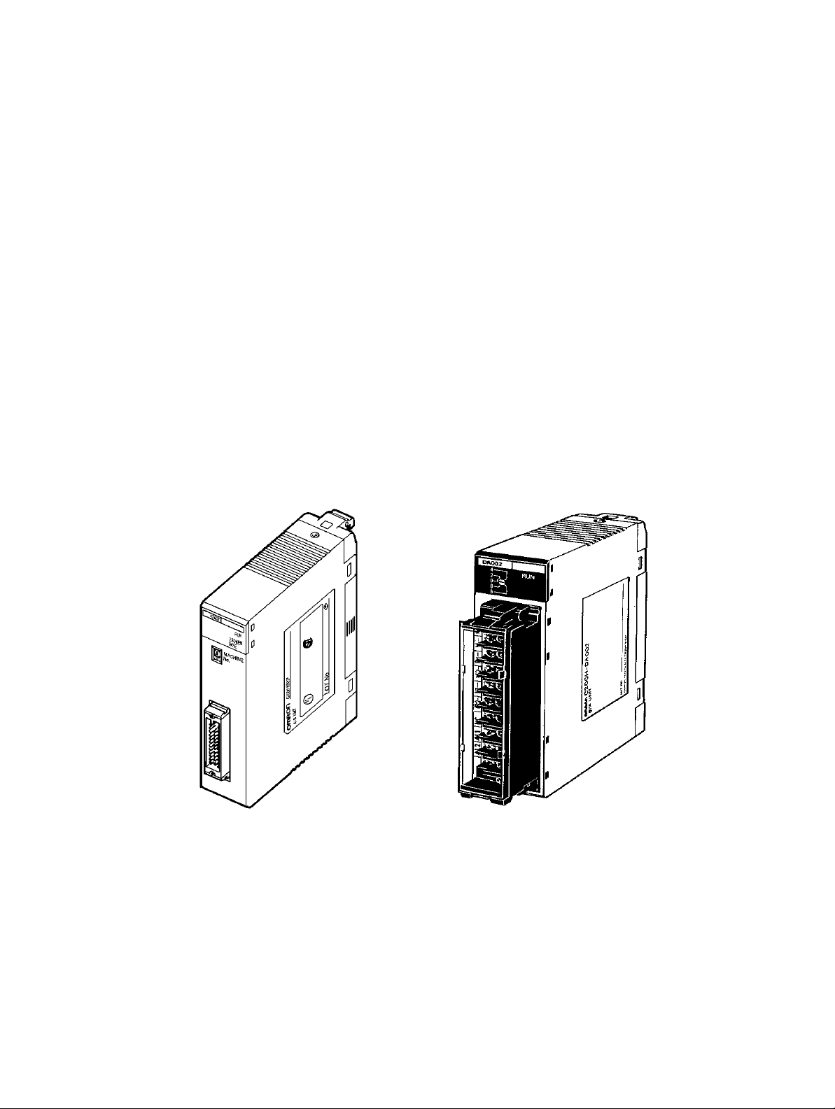
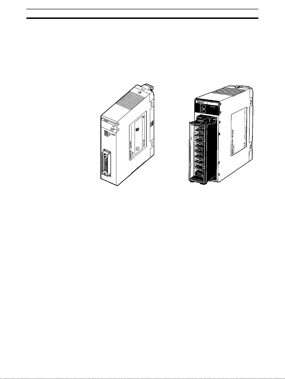
C200H-AD002/DA002
Analog I/O Units
Operation Guide
Revised July 2000
Page 2

iv
Page 3

Notice:
OMRON products are manufactured for use according to proper procedures by a qualified operator
and only for the purposes described in this manual.
The following conventions are used to indicate and classify precautions in this manual. Always heed
the information provided with them. Failure to heed precautions can result in injury to people or damage to the product.
DANGER Indicates an imminently hazardous situation which, if not avoided, will result in death or
!
serious injury.
WARNING Indicates a potentially hazardous situation which, if not avoided, could result in death or
!
serious injury.
Caution Indicates a potentially hazardous situation which, if not avoided, may result in minor or
!
moderate injury, or property damage.
OMRON Product References
All OMRON products are capitalized in this manual. The word “Unit” is also capitalized when it refers
to an OMRON product, regardless of whether or not it appears in the proper name of the product.
The abbreviation “Ch,” which appears in some displays and on some OMRON products, often means
“word” and is abbreviated “Wd” in documentation in this sense.
The abbreviation “PC” means Programmable Controller and is not used as an abbreviation for anything else.
Visual Aids
The following headings appear in the left column of the manual to help you locate different types of
information.
OMRON, 1995
All rights reserved. No part of this publication may be reproduced, stored in a retrieval system, or transmitted, in any
form, or by any means, mechanical, electronic, photocopying, recording, or otherwise, without the prior written permission of OMRON.
No patent liability is assumed with respect to the use of the information contained herein. Moreover, because OMRON is
constantly striving to improve its high-quality products, the information contained in this manual is subject to change
without notice. Every precaution has been taken in the preparation of this manual. Nevertheless, OMRON assumes no
responsibility for errors or omissions. Neither is any liability assumed for damages resulting from the use of the information contained in this publication.
Note Indicates
1, 2, 3...
information of particular interest for ef
of the product.
1. Indicates lists of one sort or another, such as procedures, checklists, etc.
ficient and convenient operation
v
Page 4

vi
Page 5

TABLE OF CONTENTS
PRECAUTIONS . . . . . . . . . . . . . . . . . . . . . . . . . . . . . . . . .
1 Intended Audience . . . . . . . . . . . . . . . . . . . . . . . . . . . . . . . . . . . . . . . . . . . . . . . . . . . . . . . . . . .
2 General Precautions . . . . . . . . . . . . . . . . . . . . . . . . . . . . . . . . . . . . . . . . . . . . . . . . . . . . . . . . . .
3 Safety Precautions . . . . . . . . . . . . . . . . . . . . . . . . . . . . . . . . . . . . . . . . . . . . . . . . . . . . . . . . . . .
4 Operating Environment Precautions . . . . . . . . . . . . . . . . . . . . . . . . . . . . . . . . . . . . . . . . . . . . .
5 Application Precautions . . . . . . . . . . . . . . . . . . . . . . . . . . . . . . . . . . . . . . . . . . . . . . . . . . . . . .
SECTION 1
System Design . . . . . . . . . . . . . . . . . . . . . . . . . . . . . . . . . . .
1-1 Introduction . . . . . . . . . . . . . . . . . . . . . . . . . . . . . . . . . . . . . . . . . . . . . . . . . . . . . . . . . . . .
1-2 Safety Precautions . . . . . . . . . . . . . . . . . . . . . . . . . . . . . . . . . . . . . . . . . . . . . . . . . . . . . . .
1-3 Basic Configuration . . . . . . . . . . . . . . . . . . . . . . . . . . . . . . . . . . . . . . . . . . . . . . . . . . . . . .
1-4 Example Configurations . . . . . . . . . . . . . . . . . . . . . . . . . . . . . . . . . . . . . . . . . . . . . . . . . . .
1-5 System Considerations . . . . . . . . . . . . . . . . . . . . . . . . . . . . . . . . . . . . . . . . . . . . . . . . . . . .
SECTION 2
C200H-AD002 Analog Input Unit . . . . . . . . . . . . . . . . . .
2-1 Before Operation . . . . . . . . . . . . . . . . . . . . . . . . . . . . . . . . . . . . . . . . . . . . . . . . . . . . . . . .
2-2 Bit and DM Area Allocations . . . . . . . . . . . . . . . . . . . . . . . . . . . . . . . . . . . . . . . . . . . . . .
2-3 Functions and Programming . . . . . . . . . . . . . . . . . . . . . . . . . . . . . . . . . . . . . . . . . . . . . . .
2-4 Data Setting and Programming Examples . . . . . . . . . . . . . . . . . . . . . . . . . . . . . . . . . . . . .
2-5 Troubleshooting . . . . . . . . . . . . . . . . . . . . . . . . . . . . . . . . . . . . . . . . . . . . . . . . . . . . . . . . .
SECTION 3
C200H-DA002 Analog Output Units . . . . . . . . . . . . . . . .
3-1 Before Operation . . . . . . . . . . . . . . . . . . . . . . . . . . . . . . . . . . . . . . . . . . . . . . . . . . . . . . . .
3-2 Bit and DM Allocations . . . . . . . . . . . . . . . . . . . . . . . . . . . . . . . . . . . . . . . . . . . . . . . . . . .
3-3 Troubleshooting . . . . . . . . . . . . . . . . . . . . . . . . . . . . . . . . . . . . . . . . . . . . . . . . . . . . . . . . .
Appendices
A Standard Models . . . . . . . . . . . . . . . . . . . . . . . . . . . . . . . . . . . . . . . . . . . . . . . . . . . . . . . . . . .
B Specifications . . . . . . . . . . . . . . . . . . . . . . . . . . . . . . . . . . . . . . . . . . . . . . . . . . . . . . . . . . . . . .
C Data Memory Coding Sheet . . . . . . . . . . . . . . . . . . . . . . . . . . . . . . . . . . . . . . . . . . . . . . . . . .
Index . . . . . . . . . . . . . . . . . . . . . . . . . . . . . . . . . . . . . . . . . .
Revision History . . . . . . . . . . . . . . . . . . . . . . . . . . . . . . . . .
vii
Page 6

About this Manual:
This manual describes the installation and operation of the C200H-AD002 Analog Input Unit and the
C200H-DA002 Analog Output Unit and includes the sections described below.
The
C200H-AD002 Analog Input Unit
digital-analog converters designed to work with the C200H or C200HS PC.
The
C200H-AD002 can convert up to eight analog inputs into digital form.
four
input ranges: 1 to 5 V
value, peak value, and square root, are built-in.
C200H-DA002 can convert four digital signals into analog outputs. The operator can select from two
The
output ranges: –10 to 10 V and 4 to 20 mA.
Please
to install and operate the C200H-AD002 or the C200H-DA002.
read this manual carefully and be sure you understand the information provided before attempting
, 0 to 10 V
and the C200H-DA002 Analog Output Unit are analog-digital and
The operator can select from
, –10 to 10 V
, and 4 to 20 mA. Useful functions, such
as scaling, mean
Section 1
Section
tion and wiring through programming and operation.
Section
tion and wiring through programming and operation.
The
sheet.
describes the types of applications in which Analog I/O Units are used.
2
describes the installation and operation of the C200H-AD002 Analog Input Unit, from installa
3
describes the installation and operation of the C200H-DA002 Analog Output Unit, from installa
Appendices
provide information on standard models, specifications, and a data memory coding
-
-
!
WARNING Failure to read and understand the information provided in this manual may result in
personal injury or death, damage to the product, or product failure. Please read each
section
and related sections before attempting any of the procedures or operations given.
in its entirety and be sure you understand the information provided
in the section
ix
Page 7

PRECAUTIONS
This section provides general precautions for using the Programmable Controller (PC) and Analog I/O Units.
information contained in this section
The
You must read this section and understand the information contained before attempting to set up or operate a PC
system and Analog I/O Units.
1 Intended Audience . . . . . . . . . . . . . . . . . . . . . . . . . . . . . . . . . . . . . . . . . . . . . . . . . . . . . . . . . . . .
2 General Precautions . . . . . . . . . . . . . . . . . . . . . . . . . . . . . . . . . . . . . . . . . . . . . . . . . . . . . . . . . . .
3 Safety Precautions . . . . . . . . . . . . . . . . . . . . . . . . . . . . . . . . . . . . . . . . . . . . . . . . . . . . . . . . . . . .
4 Operating Environment Precautions . . . . . . . . . . . . . . . . . . . . . . . . . . . . . . . . . . . . . . . . . . . . . .
5 Application Precautions . . . . . . . . . . . . . . . . . . . . . . . . . . . . . . . . . . . . . . . . . . . . . . . . . . . . . . . .
is important for the safe and r
eliable application of the Analog I/O Units.
xi
Page 8

Safety Precautions
1 Intended Audience
This
manual is intended for the following personnel, who must also have knowl
edge of electrical systems (an electrical engineer or the equivalent).
• Personnel in charge of installing FA systems
• Personnel in charge of designing FA systems
• Personnel in charge of managing FA systems and facilities
2 General Precautions
The
user must operate the product according to the performance specifications
described in the operation manuals.
Before
using the product under conditions which are
or applying the product to nuclear control systems, railroad systems, aviation
systems, vehicles, combustion systems, medical equipment, amusement
machines,
may
your OMRON representative.
Make sure that the ratings and performance characteristics of the product are
sufficient
systems, machines, and equipment with double safety mechanisms.
This
log
I/O Units. Be sure to
and keep this manual close at hand for reference during operation.
safety equipment, and other systems, machines,
have a serious influence on lives and property if
for
manual provides
3
-
not described in the manual
and equipment that
used improperly
the systems, machines, and equipment, and be sure to provide the
information for programming and operating OMRON Ana
read this manual before attempting to use the software
, consult
-
WARNING It is extremely important that a PC and all PC Units be used for the specified
!
purpose
directly or indirectly affect human life. You must consult with your OMRON
representative before applying a PC System to the above-mentioned
applications.
3 Safety Precautions
WARNING Do not attempt to take any Unit apart while power is being supplied. Doing so
!
may result in electric shock.
WARNING Do not touch any of the terminals or terminal blocks while power is being
!
supplied. Doing so may result in electric shock.
and under the specified conditions, especially in applications that can
xii
Page 9

Application Precautions
4 Operating Environment Precautions
Caution Do not operate the control system in the following places:
!
• Locations subject to direct sunlight.
• Locations subject to temperatures or humidity outside the range specified in
the specifications.
• Locations
ture.
• Locations subject to corrosive or flammable gases.
• Locations subject to dust (especially iron dust) or salts.
• Locations subject to exposure to water, oil, or chemicals.
• Locations subject to shock or vibration.
subject to condensation as the result of severe changes in tempera
5
-
Caution Take
!
Caution The
!
appropriate and suf
following locations:
• Locations subject to static electricity or other forms of noise.
• Locations subject to strong electromagnetic fields.
• Locations subject to possible exposure to radioactivity.
• Locations close to power supplies.
operating environment of the PC
gevity
and reliability of the system. Improper operating environments can lead to
malfunction,
sure
that the operating environment is within the specified conditions at installa
tion and remains within the specified conditions during the life of the system.
failure, and other
5 Application Precautions
Observe the following precautions when using the PC.
WARNING Always heed these precautions. Failure to abide by the following precautions
!
could lead to serious or possibly fatal injury.
• Always
necting to a ground of 100 Ω or less may result in electric shock.
• Always
ing. Not turning off the power supply may result in malfunction or electric
shock.
connect to a ground of 100 Ω or
turn of
f the power supply to the PC before attempting any of the follow
• Mounting
other Units.
• Assembling the Units.
• Setting DIP switch or rotary switches.
• Connecting or wiring the cables.
• Connecting or disconnecting the connectors.
or dismounting I/O Units, CPU Units, Memory Cassettes, or any
ficient countermeasures when installing systems in the
System can have a large ef
unforeseeable problems with the PC System. Be
less when installing the Units. Not con
fect on the lon
-
-
-
-
Caution Failure
!
PC
cautions.
• Fail-safe measures must be taken by the customer to ensure safety in the
to abide by the following precautions could lead to faulty operation of the
or the system, or
event
of incorrect, missing, or abnormal signals caused by broken signal lines,
momentary power interruptions, or other causes.
could damage the PC or PC Units. Always heed these pre
-
xiii
Page 10

Application Precautions
5
• Interlock
(i.e.,
• Always use the power supply voltage specified in this manual. An incorrect
voltage may result in malfunction or burning.
• Take
voltage
power
• Do not apply voltages to the Input Units in excess of the rated input voltage.
Excess voltages may result in burning.
• Do not apply voltages or connect loads to the Output Units in excess of the
maximum switching capacity. Excess voltage or loads may result in burning.
• Install
ing
result in burning.
• Disconnect
tests.
• Do not attempt to disassemble, repair, or modify any Units.
• Be sure that all the mounting screws, terminal screws, and cable connector
screws
tightening torque may result in malfunction.
• Leave
sult in malfunction if foreign matter such as wire cuttings enter the Unit.
• Remove
tion. Leaving the label attached may result in malfunction.
• Use
terminals. Connection of bare stranded wires may result in burning.
• Double-check
ing may result in burning.
• Wire all connections correctly.
• Mount the Unit only after checking the terminal block completely.
• Be
items with locking devices are properly locked into place. Improper locking
may result in malfunction.
• Check
Unit. Not checking the program may result in an unexpected operation.
• Confirm
the following. Not doing so may result in an unexpected operation.
• Resume
the DM Area, HR Area, and other data required for resuming operation. Not
doing so may result in an unexpected operation.
• Do
either of these may break the cables.
• Do
break the cables.
• Before touching the Unit, be sure to first touch a grounded metallic object in
order
damage.
• Install the Units properly as specified in the operation manuals. Improper
installation of the Units may result in malfunction.
circuits, limit circuits,
not in the Programmable Controller) must be provided by the customer
appropriate measures to ensure that the specified power with the rated
and frequency is supplied. Be particularly careful in places where the
supply is unstable. An incorrect power supply may result in malfunction.
external breakers and take other safety measures against short-circuit
in external wiring. Insuf
the functional ground terminal when
Not disconnecting the functional ground terminal may result in burning.
are tightened to the torque specified in the
the label attached to
the label after the completion of wiring to ensure proper heat dissipa
crimp terminals for wiring. Do not connect bare stranded wires directly to
all the wiring before turning on the power supply
sure that the terminal blocks, Memory
the user program for proper execution before actually running it on the
that no adverse ef
• Changing the operating mode of the PC.
• Force-setting/force-resetting any bit in memory.
• Changing the present value of any word or any set value in memory.
operation only after transferring to the new CPU Unit the contents of
not pull on the cables or bend the cables beyond their natural limit.
not place objects on top of the cables or other wiring lines. Doing so may
to discharge any static built-up. Not doing so
and similar safety measures in external circuits
ficient safety measures against short-circuiting may
performing withstand voltage
relevant manuals. Incorrect
the Unit when wiring. Removing the label may re
. Incorrect wir
Units, expansion cables, and other
fect will occur in the system before attempting any of
Doing
may result in malfunction or
.
-
-
-
-
xiv
Page 11

This
section describes the basic uses of Analog I/O Units in a control system and
they might be found.
1-1 Introduction . . . . . . . . . . . . . . . . . . . . . . . . . . . . . . . . . . . . . . . . . . . . . . . . . . . . . . . . . . . . .
1-2 Safety Precautions . . . . . . . . . . . . . . . . . . . . . . . . . . . . . . . . . . . . . . . . . . . . . . . . . . . . . . . .
1-3
Basic Configuration
1-4 Example Configurations . . . . . . . . . . . . . . . . . . . . . . . . . . . . . . . . . . . . . . . . . . . . . . . . . . . .
1-5
System Considerations
. . . . . . . . . . . . . . . . . . . . . . . . . . . . . . . . . . . . . . . . . . . . . . . . . . . . . . .
. . . . . . . . . . . . . . . . . . . . . . . . . . . . . . . . . . . . . . . . . . . . . . . . . . . . .
illustrates the type of applications in which
SECTION 1
System Design
1
Page 12
Safety Precautions
1-1 Introduction
Section 1-2
The
C200H-AD002 Analog Input Unit is used to convert the output of analog field
devices, usually sensors, to a digital form that the PC can read. The
C200H-DA002
log signals which drive analog field devices.
Analog Output Unit converts the digital output of the PC to ana
-
C200H-AD002
Analog Input Unit
1-2 Safety Precautions
• Be
sure to read this manual carefully and understand the explanations before
attempting any of the procedures described herein. OMRON accepts no responsibility
eration that is not covered in this manual.
• Be sure to turn off the power supply to the PC before carrying out any of the
following operations:
a) Mounting or removing a Unit.
b) Setting switches.
c) Mounting or removing a Terminal Block or connectors.
d) Wiring the system or Units.
twisted-pair cables and keep high-voltage lines and power lines in sepa
• Use
rate ducts to reduce the risk of malfunctions due to electrical noise.
C200H-DA002
Analog Output Unit
for any damage or injury that may result from carrying out any op
-
-
• Before
• Check to be sure that the user program operates correctly.
turning on the power supply
and wiring are correct.
, check to be sure that the switch settings
2
Page 13
Basic Configuration
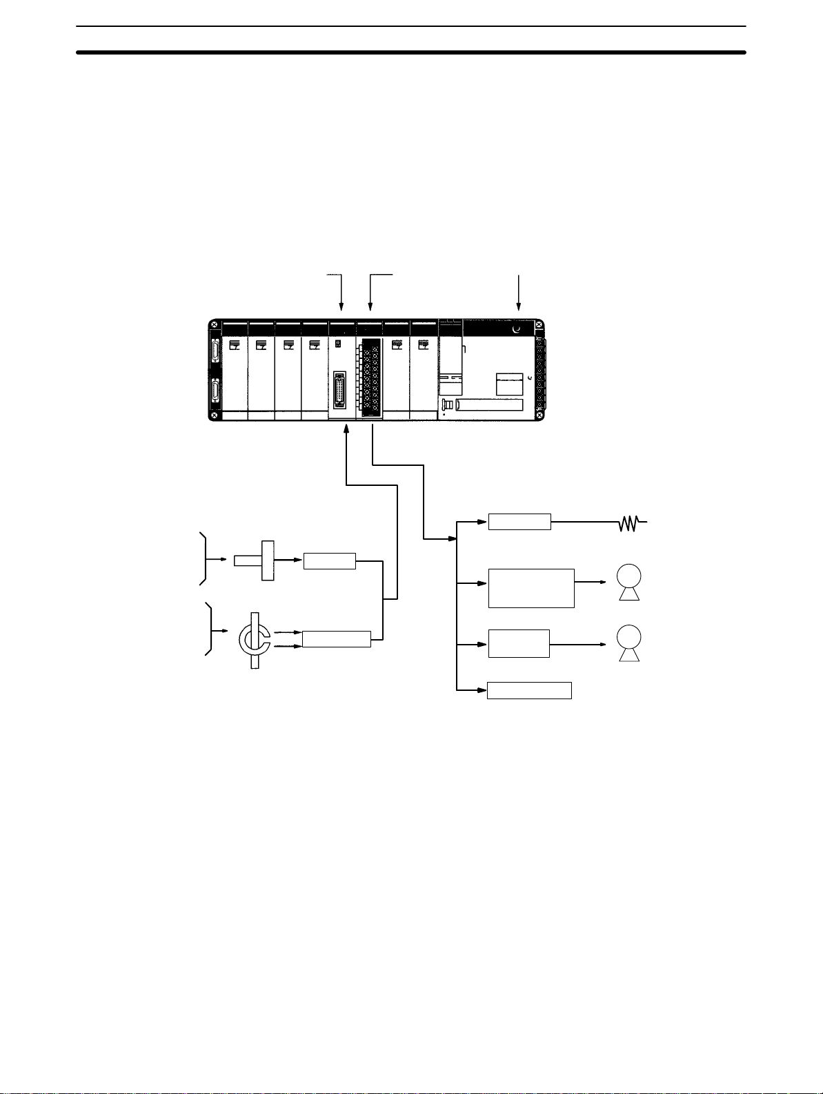
1-3 Basic Configuration
This
diagram shows some of the possible field devices for the Analog I/O Units.
Any
I/O device can be used as long as voltage/current requirements fall within
the specified ranges.
The
I/O device connected to the Analog I/O Unit will often serve as an interface
for
another device. For example, a preamplifier may amplify the output of a
sure gauge to the level required for the Analog Input Unit and a regulator may
interface a heating system to control temperature.
Section 1-3
pres
-
Temperature
Pressure
Speed
Flowrate
Voltage
Current
Power
Power factor
C200H-AD002
Analog Input Unit
Sensor
Preamp
Transducer
C200H-DA002
Analog
Output Unit
CPU
Regulator
Variable
speed
controller
Servocontroller
SYSMAC
C200HS,
C200H,
C200HX/HG/HE
(T
emperature control)
(Speed control)
(Position control)
M
M
Sensor
Chart recorder
3
Page 14
Example Configurations
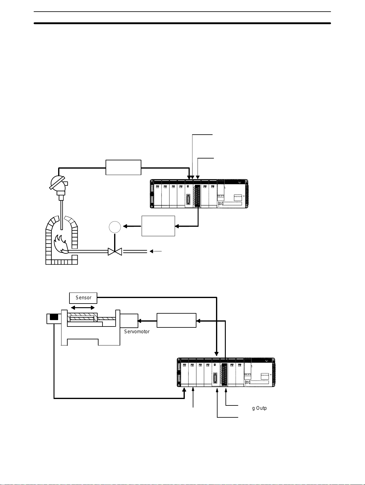
1-4 Example Configurations
Below
are two examples of how Analog I/O Units can be used in control systems.
The
first diagram
a servomotor positioning system.
Transducer
Temperature
sensing element
shows a temperature regulating system and the second shows
Section 1-4
C200H-AD002
Analog Input Unit
C200H-DA002
Analog Output Unit
SYSMAC C200HS, C200H, C200HX/HG/HE
Encoder
Sensor
Platform
M
M
Servomotor
Locating pulse
Valve
controller
Fuel
Servo
controller
SYSMAC C200HS, C200H, C200HX/HG/HE
C200H-DA002
C200H-CT001-V1
High-speed Counter Unit
Analog Output Unit
C200H-AD002
Analog Input Unit
4
Page 15

System Considerations
1-5 System Considerations
Section 1-5
Number of Units The
Analog I/O Units are classified as Special I/O Units for the C200HS, C200H,
and
C200HX/HG/HE. For most Units, a maximum total
(including PC Link Units) can be mounted to the CPU Rack, Expansion I/O
Racks,
Unit counts as two Units.
The
unit numbers of the
15 decimal) instead of 0 to 9 when they are used with the C200HGCPU53/CPU63
up to 16 Special I/O Units.
C200H-AD002,
numbers jj16 or later (January 1996 or later)
The Units that belong to the various Special I/O Unit groups are shown in the
following table. Their usage is limited according to the maximum current provided for the Rack and the amount of current consumed by each Unit. For details, refer to the
Slave Racks Certain
on
Slave Racks. The following table shows the maximum number of Group A, B,
C, and D Special I/O Units that can be mounted on a single Slave Rack when
only Units of that group are used.
A B C D
High-speed Counters
Position Control Units
(NC111/112)
ASCII Units
Analog I/O Units
ID Sensor Units
Fuzzy Logic Units
4 Units --- --- ---
--- 8 Units --- ---
--- --- 6 Units ---
--- --- --- 2 Units
High-density I/O Units
Temperature Control Units
PID Control Units
Cam Positioner Units
of ten Special I/O Units
and Slave Racks of a single PC. A single C200H-NC21
1 Position Control
following Units can be set to between 0 and F Hex (0 to
or C200HX-CPU54/CPU64 CPU Units. This enables
C200H-DA002, C200H-NC21
Installation Guide
.
1, and C200H-CT201 with lot
mounting
limitations apply to the number of Special I/O Units that can be
Temperature Sensor Units
Voice Units
Position Control Units
(NC211)
mounted
If
two equations must be satisfied.
Units can be mounted on other Racks as well, until the maximum total of ten
Units has been reached. Remember, however, that a single C200H-NC211
Position
among the total of ten Units.
System Configuration
Considerations
C200HS/C200H
unit
the
refer to
With
CPU. Doing so would prevent peripheral devices such as the Programming
Console from being connected.
Special I/O Units cannot be used on a C200H Remote I/O Slave Rack if the
Slave Rack is connected to different PC (i.e., C500, C1000H, or C2000H).
Precautions Be
Units or connecting lines.
Units from any of the four groups
are to be combined, then both of the following
3A + B + 2C + 6D x 12
A + B + C + D x 8
Control Unit counts as two Units. PC Link Units must also be counted
Special I/O
Units are allocated IR area words according to the
number switch settings on their front panels. They do not use the words of
slots in which they are mounted. For details regarding data area allocations,
2-2
and
3-2 IR and DM Bit Allocations
the C200H, do not mount an Analog I/O Unit in the two slots adjacent to
sure to turn of
f the power supply to the PC before installing or
.
the
disconnecting
5
Page 16

System Considerations
To
reduce the risk of malfunctioning due to electrical noise, wire
lines in separate ducts from high-voltage and power lines.
For
further wiring precautions,
log Input Units and Analog Output Units.
refer to the respective sections on wiring for Ana
Section 1-5
input and output
-
6
Page 17

SECTION 2
C200H-AD002 Analog Input Unit
This section provides the information required to install and operate a C200H-AD002 Analog Input Unit.
2-1 Before Operation . . . . . . . . . . . . . . . . . . . . . . . . . . . . . . . . . . . . . . . . . . . . . . . . . . . . . . . . .
2-1-1 Nomenclature and Functions . . . . . . . . . . . . . . . . . . . . . . . . . . . . . . . . . . . . . . . . .
2-1-2 Switch Settings . . . . . . . . . . . . . . . . . . . . . . . . . . . . . . . . . . . . . . . . . . . . . . . . . . .
2-1-3 Wiring . . . . . . . . . . . . . . . . . . . . . . . . . . . . . . . . . . . . . . . . . . . . . . . . . . . . . . . . . .
2-2
Bit and DM Area Allocations
2-3 Functions and Programming . . . . . . . . . . . . . . . . . . . . . . . . . . . . . . . . . . . . . . . . . . . . . . . .
2-3-1 Conversion Prohibit Settings . . . . . . . . . . . . . . . . . . . . . . . . . . . . . . . . . . . . . . . . .
2-3-2 Input Signal Range Setting . . . . . . . . . . . . . . . . . . . . . . . . . . . . . . . . . . . . . . . . . .
2-3-3 Conversion Data Type Setting . . . . . . . . . . . . . . . . . . . . . . . . . . . . . . . . . . . . . . . .
2-3-4 Square Root Function . . . . . . . . . . . . . . . . . . . . . . . . . . . . . . . . . . . . . . . . . . . . . .
2-3-5 Scaling Function . . . . . . . . . . . . . . . . . . . . . . . . . . . . . . . . . . . . . . . . . . . . . . . . . .
2-3-6
2-3-7
2-3-8 Limit Warning Function . . . . . . . . . . . . . . . . . . . . . . . . . . . . . . . . . . . . . . . . . . . . .
2-3-9 Input Disconnection Detection Function . . . . . . . . . . . . . . . . . . . . . . . . . . . . . . . .
2-4 Data Setting and Programming Examples . . . . . . . . . . . . . . . . . . . . . . . . . . . . . . . . . . . . . .
2-4-1
2-4-2 Programming . . . . . . . . . . . . . . . . . . . . . . . . . . . . . . . . . . . . . . . . . . . . . . . . . . . . .
2-5 Troubleshooting . . . . . . . . . . . . . . . . . . . . . . . . . . . . . . . . . . . . . . . . . . . . . . . . . . . . . . . . . .
Mean V
Peak V
Data Settings
alue Function . . . . . . . . . . . . . . . . . . . . . . . . . . . . . . . . . . . . . . . . . . . . . . .
alue Function . . . . . . . . . . . . . . . . . . . . . . . . . . . . . . . . . . . . . . . . . . . . . . .
. . . . . . . . . . . . . . . . . . . . . . . . . . . . . . . . . . . . . . . . . . . . . . . .
. . . . . . . . . . . . . . . . . . . . . . . . . . . . . . . . . . . . . . . . . . . . . . . . . . . . .
7
Page 18
Before Operation Section 2-1
2-1 Before Operation
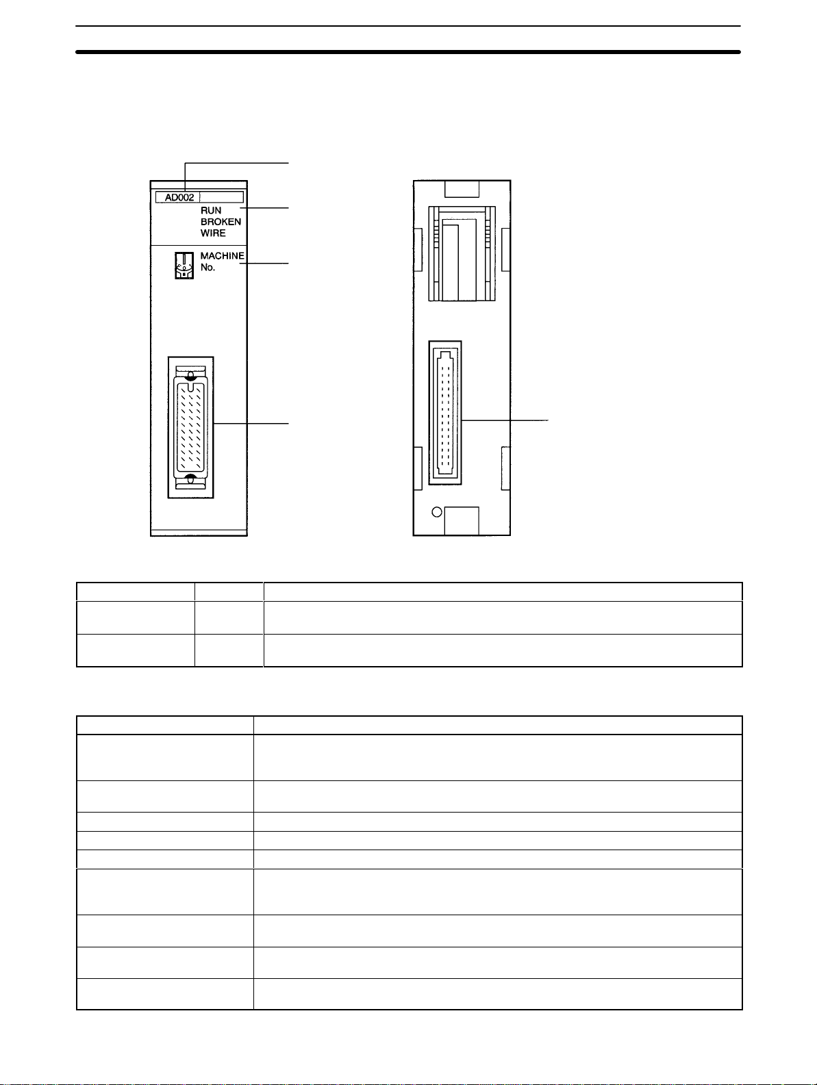
2-1-1 Nomenclature and Functions
Front Back
number label
Model
Indicators
Unit number switch
Input connector
Connector to Backplane
Indicators
Indicator Color Function
RUN Green Lit when the Analog Input Unit is operating correctly. If operation is not normal, this
indicator turns OFF and Unit operation is stopped.
BROKEN WIRE Red Lit when an input signal wire is disconnected. This indicator operates only when the
input range is set to 1 to 5 V/4 to 20 mA.
Functions The following table briefly outlines the basic functions of the C200H-AD002.
These
functions are covered in more detail in
Function Explanation
Conversion prohibit setting Unnecessary conversion processing time can be reduced by disabling analog-to-digital
conversion for unused inputs. Disabling conversion can also reduce the sampling
period for each input.
Input range setting The input range can be set for each input number according to the input signal level
that is to be used.
Conversion data type setting Sets whether the converted digital output is BCD or binary.
Square root Converts quadratic data, such as thermocouple input, to linear data.
Scaling Converts an analog input signal to a preset range of BCD data for output.
Mean value Sums the sampling data for the specified number of samples, eliminates the minimum
and maximum values, calculates the mean value from the remaining values, and
outputs that value.
Peak value Holds the maximum values for A/D conversion data, scaling data, mean data, and
square root data, and outputs them as output data.
Limit warning The Warning Flag is turned ON if the A/D conversion data, scaling data, mean data, or
square root data exceeds the specified upper- or lower-limit values.
Disconnection detection The Disconnection Detection Flag is turned ON and the BROKEN WIRE indicator is lit if
the input signal wire becomes disconnected when 1 to 5 V/4 to 20 mA are set.
2-3 Functions and Programming
.
8
Page 19
Before Operation Section 2-1
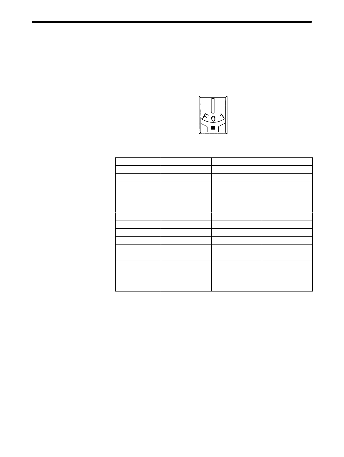
2-1-2 Switch Settings
Unit Number Switch The unit number (MACHINE No.) is the only setting necessary on the Analog
Input
Unit. Always turn of
blade
screwdriver
, being careful not to damage the slot in
to leave the switch midway between settings.
Switch setting Unit number IR words DM words
0 Unit #0 IR 100 to 109 DM 1000 to 1043
1 Unit #1 IR 1
2 Unit #2 IR 120 to 129 DM 1200 to 1243
3 Unit #3 IR 130 to 139 DM 1300 to 1343
4 Unit #4 IR 140 to 149 DM 1400 to 1443
5 Unit #5 IR 150 to 159 DM 1500 to 1543
6 Unit #6 IR 160 to 169 DM 1600 to 1643
7 Unit #7 IR 170 to 179 DM 1700 to 1743
8 Unit #8 IR 180 to 189 DM 1800 to 1843
9 Unit #9 IR 190 to 199 DM 1900 to 1943
A Unit #10 IR 400 to 409 DM 2000 to 2043
B Unit #11 IR 410 to 419 DM 2100 to 2143
C Unit #12 IR 420 to 429 DM 2200 to 2243
D Unit #13 IR 430 to 439 DM 2300 to 2343
E Unit #14 IR 440 to 449 DM 2400 to 2443
F Unit #15 IR 450 to 459 DM 2500 to 2543
f the power before setting the unit number
the screw
10 to 1
19 DM 1
100 to 1
. Use a flat-
. Be sure not
143
Note 1. The unit number setting switch is factory set to 0.
2. If
3. Make
4. The
2-1-3 Wiring
Compatible Connector One
MR-34FG Connector and MR-34L Cover made by Honda Communications.
two or more Special I/O Units are assigned the same unit
number
, an I/O
UNIT OVER error will be generated and the PC will not operate.
the unit number settings with the power turned of
are made with the power on, they will not go into ef
tings
f to the PC. If the set
fect
until either the
power is turned off and then on again or the Special I/O Unit Restart Flag
(AR0100 to AR0109) is turned ON and then OFF again.
unit number can
be set to between A and F Hex (10 to 15 decimal) only
when a C200H-AD002 with a lot number jj16 or later (January 1996 or
later) is used with a C200HG-CPU53/CPU63 or C200HX-CPU54/CPU64
CPU Unit.
MR-34LFG Connector Set is included with each Unit. The set includes an
9
-
Page 20
Before Operation Section 2-1
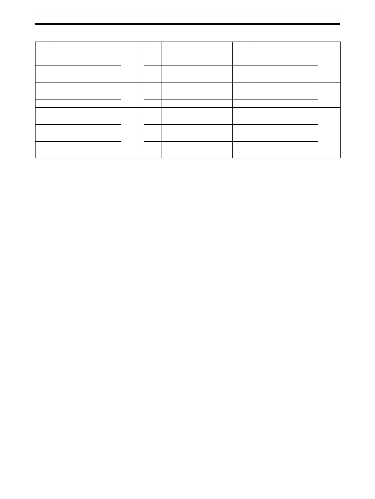
Pin Allocation
Pin
no.
12 Common (–)
11 Current input (+) --- --- 33 Current input (+)
10 Voltage/Current input (+) 22 Analog ground (AG) 32 Voltage/Current input (+)
9 Common (–)
8 Current input (+) 20 Shield 30 Current input (+)
7 Voltage/Current input (+) 19 Shield 29 Voltage/Current input (+)
6 Common (–)
5 Current input (+) 17 Shield 27 Current input (+)
4 Voltage/Current input (+) 16 Shield 26 Voltage/Current input (+)
3 Common (–)
2 Current input (+) 14 Shield 24 Current input (+)
1 Voltage/Current input (+) 13 Frame ground (FG) 23 Voltage/Current input (+)
Name Pin
no.
Input 7
Input 5
Input 3
Input 1
--- --- 34 Common (–)
21 Shield 31 Common (–)
18 Shield 28 Common (–)
15 Shield 25 Common (–)
Name Pin
no.
Name
Input 8
Input 6
Input 4
Input 2
Note 1. Short
ing a current input.
2. All of the shield terminals (terminals 14 through 21) are shorted within the
Unit. Wire each input’s shield wire to any of these terminals.
the current input (+) and voltage/current input (+) terminals when us
-
10
Page 21

Before Operation Section 2-1
Input Wiring Diagram
Voltage
input
0 V
V
COM
C200H-AD002
1 M
1 M
Ω
Ω
Current input
0 V
Shield
V/I
I
COM
Shield
FG
AG
V
I
COM
FG
AG
250
FG
0V
and V/I
10 k
Ω
0 V
1 M
Ω
Ω
1 M
Ω
10 k
Ω
0 V
: V
oltage/current input (+)
: Current input (+)
: Common (–)
: Frame ground
(Connected to the FG of the CPU
or Power Supply
: Analog ground
(Connected to 0 V within the cir
cuit.)
.)
-
Note The
a frame ground.
AG terminal is a ground terminal for the
analog input. Do not connected it to
11
Page 22

Before Operation Section 2-1
Wiring Methods Use the connectors provided with the Unit to wire input lines. (Connec-
tor: MR-34FG;
Connector/Cover Set: MR-34LFG).
sure to tighten the lock screws whenever attaching the connector to the Unit.
Be
Use wires with a diameter of 0.3 mm2 maximum.
Cover: MR-34L; both manufactured by Honda Communications;
iring Method
W
Connector
Heat-shrinking
tube
Wiring
Connector Assembly
Round-head screw
Cover
Connector
lock screw
Connector
(jack)
Do not forget to connect one of cable shield terminals to the FG terminal.
Do
not remove the protective seal from the Unit until wiring
This
seal will prevent wire clippings and other debris from entering the Unit and
possibly
If
the
preventing proper
operation. Always remove this seal before operation.
seal is left in place, the Unit may overheat, possibly causing improper op
has been completed.
eration or damage to the Unit.
Before Wiring After Wiring
-
Remove
the label.
12
Page 23

Before Operation Section 2-1
Input Wiring
Considerations
When wiring inputs, apply the following points to avoid noise interference and
optimize Analog Input Unit performance.
• Use shielded twisted-pair cable for external connections and power lines.
• Route input cables separately from the AC cable, and do not run the Unit’s
cables
near a main circuit cable, high voltage cable, or a non-PC load
cable.
• Be sure to install surge-absorbing diodes or surge absorbers for inductive
loads (relays, solenoids, electromagnetic valves, etc.) They should be
installed
right next to relays and solenoids. Use surge-absorbing diodes with a
dielectric strength of at least five times the circuit voltage.
DC Relay
Surge-absorbing
diode
Solenoid, etc.
AC Relay
Surge absorber
Surge absorber
• If
there is noise interference from power lines (if, for example, the power supply
is
shared with electrical welding devices or electrical discharge machines, or if
there
is a high-frequency generation source nearby) install a noise filter at the
power supply input area.
• Connect
to a ground of 100 Ω or less, with as heavy a wire as possible (i.e., at
least 1.25 mm2).
13
Page 24

Bit and DM Area Allocations
2-2 Bit and DM Area Allocations
Section 2-2
IR Area Allocation The
area
allocated
on
fresh
refresh cycle by the PC.
SYSMAC C200HS, C200H, C200HX/HG/HE
(W
ork area)
Unit #0
Unit #1
Unit #2
Unit #3
Unit #4
Unit #5
Unit #6
Unit #7
Unit #8
Unit #9
Unit #10
Unit #1
Unit #12
Unit #13
Unit #14
Unit #15
IR 100 to 109
IR 1
IR 120 to 129
IR 130 to 139
IR 140 to 149
IR 150 to 159
IR 160 to 169
IR 170 to 179
IR 180 to 189
IR 190 to 199
IR 400 to 409
1
IR 410 to 419
IR 420 to 429
IR 430 to 439
IR 440 to 449
IR 450 to 459
10 to 1
Analog Input Units are allocated ten words each from the portion of the
(IR 100 to IR 199) that is reserved for Special I/O Units. The words that are
a particular Analog Input Unit depend on the setting of the unit number
the front panel of the Unit. Those ten words are then reserved as an I/O
data area, and the bits that comprise that area are refreshed with every I/O
C200H-AD002 Analog Input Unit
(I/O refresh data area)
19
At the I/O refresh by the
PC, outputs (PC to Unit)
and inputs (Unit to PC)
are refreshed in order
with every cycle.
IR n
IR
n + 1
to
IR n +9
(n = 100 + 10 x unit number)
The OUT and IN refreshes are as seen
from the PC.
OUT refresh
IN refresh
IR
re
-
Note 1. The
other
UNIT OVER error will be generated and operation will be stopped.
2. The
when a C200H-AD002 with a lot number jj16 or later (January 1996 or
later) is used with a C200HG-CPU53/CPU63 or C200HX-CPU54/CPU64
CPU Unit.
unit number that is set for an Analog Input Unit must not be
used for any
Special I/O Unit. If the same unit number is set more than once, an I/O
unit number can
be set to between A and F Hex (10 to 15 decimal) only
14
Page 25

Bit and DM Area Allocations
DM Area Allocation
Section 2-2
SYSMAC C200HS, C200H, C200HX/HG/HE
(DM area)
Unit #0
Unit #1
Unit #2
Unit #3
Unit #4
Unit #5
Unit #6
Unit #7
Unit #8
Unit #9
Unit #10
Unit #1
Unit #12
Unit #13
Unit #14
Unit #15
DM 1000 to 1043
DM 1
100 to 1
DM 1200 to 1243
DM 1300 to 1343
DM 1400 to 1443
DM 1500 to 1543
DM 1600 to 1643
DM 1700 to 1743
DM 1800 to 1843
DM 1900 to 1943
DM 2000 to 2043
DM 2100 to 2143
1
DM 2200 to 2243
DM 2300 to 2343
DM 2400 to 2443
DM 2500 to 2543
143
Automatically transferred
to each Unit at power up
or when Special I/O Re
start Flag is turned ON.
C200H-AD002 Analog Input Unit
(Fixed data area)
DM (m)
to
DM (m+ 3)
DM
(m + 4)
to
DM (m +19)
DM (m + 20)
to
DM (m + 27)
DM (m + 28)
to
DM (m + 43)
(m = 1000 + 100 x unit number)
Parameter
Scaling data
Mean value
data
Limit warning
data
(For more information regarding DM area allocation, refer to
Allocations
at the end of this section.)
Note The
unit number can be set to between A and F Hex (10 to 15 decimal) only when
a
C200H-AD002 with a lot number jj16 or later (January 1996 or later) is used
with a C200HG-CPU53/CPU63 or C200HX-CPU54/CPU64 CPU Unit.
IR Allocations
I/O Wd
(IR)
15 14 13 12 11 10 09 08 07 06 05 04 03 02 01 00
Out n 0 0
In
n+1 Sign Input 1 A/D conversion data or processing data
n+2 Sign Input 2 A/D conversion data or processing data
n+3 Sign Input 3 A/D conversion data or processing data
n+4 Sign Input 4 A/D conversion data or processing data
n+5 Sign Input 5 A/D conversion data or processing data
n+6 Sign Input 6 A/D conversion data or processing data
n+7 Sign Input 7 A/D conversion data or processing data
n+8 Sign Input 8 A/D conversion data or processing data
n+9
Input 8Input 7 Input 6 Input 5 Input 4 Input 3 Input 2 Input 1 Input 8 Input 7 Input 6 Input 5 Input 4 Input 3 Input 2 Input 1
Limit warning Disconnection detection
Unit numbers 0 to 9: n = 100 + 10 x unit number
Unit numbers 10 to 15: n = 400 + 10 x (unit number – 10)
A/D Conversion Data
Input range Binary data BCD data
0 to 10 V, 1 to 5 V, or 4 to 20 mA
–10 to 10 V 87D0 to 8001, 0000 to 07D0
(–07D0 to –0001, 0000 to 07D0)
0000 to 0F
DM
Bit
Peak value execution
Input 8Input 7 Input 6 Input 5 Input 4 Input 3 Input 2 Input 1
A0
0000 to 4000
A000 to 8001, 0000 to 2000
(–2000 to –0001, 0000 to 2000)
15
Page 26

econversiondata range isas follows
ge
The conversion data range is as follows when the in ut signal range
ggg
Bi
87D0 to8001,0000 to07D0
Abi
f0indi
f1indi
g
)
being executed.)
g
square root functions are out ut here when those functions are being
Bit and DM Area Allocations
Section 2-2
Note When
status of 0 indicates “+” and a bit status of 1 indicates “–.” There is no sign bit
when the scaling or square root function is being executed.
Processing Data When
executed, the resulting data is output.
Note When scaling is executed, it is set in IR words n+1 through n+8 in BCD.
IR Area Contents: Outputs
Word
(IR)
n
Address
15
07 to 00
Bit
to 08
--- Not used. Set these bits to 00 (OFF).
Peak Value ON Bits Turn these bits to 1 (ON) to execute the peak value function for the
Item Contents
IR Area Contents: Inputs
Word
(IR)
n+1 15
n+2
n+3
n+4
n+5
n+6
n+7
n+8
n+9
Bit Item Contents
to 00
Input 1 A/D conversion data
or processing data
15 to 00
Input 2 A/D conversion data
or processing data
15 to 00
Input 3 A/D conversion data
or processing data
15 to 00
Input 4 A/D conversion data
or processing data
15 to 00
Input 5 A/D conversion data
or processing data
15 to 00
Input 6 A/D conversion data
or processing data
15 to 00
Input 7 A/D conversion data
or processing data
15 to 00
Input 8 A/D conversion data
or processing data
15 to 08
07 to 00
Limit warning When the limit warning has been set, these bits are turned ON to
Disconnection detection These bits are turned ON to indicate that a disconnection or broken
the input range is set to –10 V to +10 V
, the
15th bit indicates the sign. A bit
scaling, mean value processing, peak value, or square
corresponding input. Bits 00 through 07 correspond to inputs 1
through 8.
Refer to
The A/D conversion data is set here for each input.
Th
is set to 0 to 10 V, 1 to 5 V, or 4 to 20 mA:
The conversion data range is as follows when the input signal range
is set to –10 to 10 V:
When the input range is set to –10 V to +10 V
the sign.
“–.” (There is no sign bit when the scaling or square root function is
bein
The processing results for the scaling, mean value, peak value, and
square root functions are output here when those functions are bein
executed.
indicate that the corresponding input’s value has exceeded the
range. Bits 08 through 15 correspond to inputs 1 through 8.
wire has occurred in the corresponding input. Bits 00 through 07
correspond to inputs 1 through 8.
2-3-7 Peak Value Function
BCD data:
Binary data:
BCD data:
narydata:
t status o
executed.
for more details.
when the inputsignal ran
0000 to 4000
0000 to 0F
A0
A000 to 8001, 0000 to 2000
, the 15th bit indicates
“
cates“+” and a bit status o
”
root calculation is
cates
Unit numbers 0 to 9: n = 100 + 10 x unit number
Unit numbers 10 to 15: n = 400 + 10 x (unit number – 10)
DM Allocations
DM
word
m 0 0 0
m+1
m+2
m+3
16
15 14 13 12 11 10 09 08 07 06 05 04 03 02 01 00
warning
Input signal range (00 specifies –10 to +10 V, 01 specifies 0 to 10 V, and 10 specifies 1 to 5 V/4 to 20 mA.)
Input 8 Input 7 Input 6 Input 5 Input 4 Input 3 Input 2 Input 1
Scaling execution Mean value execution
Input 8Input 7 Input 6 Input 5 Input 4 Input 3 Input 2 Input 1 Input 8 Input 7 Input 6 Input 5 Input 4 Input 3 Input 2 Input 1
Square root execution Limit warning execution
Input 8Input 7 Input 6 Input 5 Input 4 Input 3 Input 2 Input 1 Input 8 Input 7 Input 6 Input 5 Input 4 Input 3 Input 2 Input 1
Limit
mode
Bit
Data
p
type
setting
Input 8Input 7 Input 6 Input 5 Input 4 Input 3 Input 2 Input 1
Conversion prohibit setting
Page 27

Bit and DM Area Allocations
Section 2-2
DM
word
word
m+4 Input 1 scaling: lower-limit value
m+5 Input 1 scaling: upper-limit value
m+6 Input 2 scaling: lower-limit value
m+7 Input 2 scaling: upper-limit value
m+8 Input 3 scaling: lower-limit value
m+9 Input 3 scaling: upper-limit value
m+10 Input 4 scaling: lower-limit value
m+11 Input 4 scaling: upper-limit value
m+12 Input 5 scaling: lower-limit value
m+13 Input 5 scaling: upper-limit value
m+14 Input 6 scaling: lower-limit value
m+15 Input 6 scaling: upper-limit value
m+16 Input 7 scaling: lower-limit value
m+17 Input 7 scaling: upper-limit value
m+18 Input 8 scaling: lower-limit value
m+19 Input 8 scaling: upper-limit value
m+20 Input 1 mean value processing: number of samples
m+21 Input 2 mean value processing: number of samples
m+22 Input 3 mean value processing: number of samples
m+23 Input 4 mean value processing: number of samples
m+24 Input 5 mean value processing: number of samples
m+25 Input 6 mean value processing: number of samples
m+26 Input 7 mean value processing: number of samples
m+27 Input 8 mean value processing: number of samples
m+28 Input 1 limit warning: lower-limit value
m+29 Input 1 limit warning: upper-limit value
m+30 Input 2 limit warning: lower-limit value
m+31 Input 2 limit warning: upper-limit value
m+32 Input 3 limit warning: lower-limit value
m+33 Input 3 limit warning: upper-limit value
m+34 Input 4 limit warning: lower-limit value
m+35 Input 4 limit warning: upper-limit value
m+36 Input 5 limit warning: lower-limit value
m+37 Input 5 limit warning: upper-limit value
m+38 Input 6 limit warning: lower-limit value
m+39 Input 6 limit warning: upper-limit value
m+40 Input 7 limit warning: lower-limit value
m+41 Input 7 limit warning: upper-limit value
m+42 Input 8 limit warning: lower-limit value
m+43 Input 8 limit warning: upper-limit value
BitDM
00010203040506070809101112131415
17
Page 28

gg
(Thefi
)
01:0to10V
10: 1 to 5 V/4 to 20 mA
Bit and DM Area Allocations
DM Contents
DM word(s) Bits Item Data contents
m
m+1
m+2
m+3
m+4
to
m+19
15 to 10
09 Limit warning mode Sets the operating mode for the limit warning function. This
08 Conversion data type Sets the data type of the conversion data to binary or BCD.
07 to 00
15 and 14
13 and 12
1
1 and 10
09 and 08
07 and 06
05 and 04
03 and 02
01 and 00
15 to 08
07 to 00
15 to 08
07 to 00
15 to 00
--- Not used.
setting applies to all 8 inputs.
0: Mode 1 (normal warning)
1: Mode 2 (sequence warning)
Refer to
This setting applies to all 8 inputs.
Conversion prohibit setting Turn these bits turned ON to disable A/D conversion for the
corresponding input. Bits 00 through 07 correspond to inputs
1 through 8.
Input signal range for input 8
Input signal range for input 7
Input signal range for input 6
Input signal range for input 5
Input signal range for input 4
Input signal range for input 3
Input signal range for input 2
Input signal range for input 1
Scaling execution Turn these bits turned ON to execute the scaling function for
Mean value execution Turn these bits turned ON to execute the mean value
Square root execution Turn these bits turned ON to execute the square root
Limit warning execution Turn these bits turned ON to execute the limit warning
Scaling data The scaling data (upper and lower limits) is set in BCD (0000
Each pair of bits sets the input signal range for the
corresponding input, as follows.
the corresponding input. Bits 08 through 15 correspond to
inputs 1 through 8.
Refer to
function for the corresponding input. Bits 00 through 07
correspond to inputs 1 through 8.
Refer to
function for the corresponding input. Bits 08 through 15
correspond to inputs 1 through 8.
Refer to
function for the corresponding input. Bits 00 through 07
correspond to inputs 1 through 8.
Refer to
to 9999), using two words for each input. Set the lower limit
in the first of the two words and the upper limit in the second,
and make sure that the lower limit is smaller than the upper
limit.
Refer to
2-3-8 Limit Warning Function
0: Binary
1: BCD
0: Conversion enabled
1: Conversion disabled
rstbitis thehigherbit.
00: –10 V to +10 V
10: 1 to 5 V/4 to 20 mA
11: Not used.
0: Scaling function won’t be executed.
1: Scaling function will be executed.
2-3-5 Scaling Function
0: Mean value function won’t be executed.
1: Mean value function will be executed.
for more details.
2-3-6 Mean Value Function
0: Square root function won’t be executed.
1: Square root function will be executed.
2-3-4 Square Root Function
0: Limit warning function won’t be executed.
1: Limit warning function will be executed.
2-3-8 Limit Warning Function
2-3-5 Scaling Function
for more details.
Section 2-2
for more details.
for more details.
for more details.
for more details.
18
Page 29

Functions and Programming
DM word(s) Data contentsItemBits
m+20
to
m+27
m+28
to
m+43
15 to 00
15 to 00
Number of terms for
calculating mean value
Limit warning data The limit warning data (upper and lower limits) is set in BCD
The number of samples to be taken for calculating the mean
value is set in BCD (0003 to 9999) for each input.
DM words m+20 through m+27 correspond to inputs 1
through 8.
Refer to
using two words for each input. Set the lower limit in the first
of the two words and the upper limit in the second, and make
sure that the lower limit is smaller than the upper limit.
The setting range is 0000 to 4000. (The scaling data’s upper
and lower limits are used when the scaling function is being
executed.)
Refer to
2-3 Functions and Programming
The C200H-AD002 Analog Input Unit provides nine functions:
2-3-6 Mean Value Function
2-3-8 Limit Warning Function
for more details.
Section 2-3
for more details.
1, 2, 3...
1. Conversion prohibit settings
2. Input signal range settings
3. Conversion data type setting
4. Square root function
5. Scaling function
6. Mean value processing function
7. Peak value function
8. Limit warning function
9. Disconnection detection function
(This function can be used with the 1 to 5 V/4 to 20 mA input range only.)
These
functions are set using Unit switches and Peripheral Devices,
Programming
DM
m+43) cannot be written from user program and all data set in these words
Console. The words allocated to the Unit
in the DM Area (DM m to
such as a
must be written from a Peripheral Device.
When inputting data from a Programming Console, use the operations to
change
present values. When inputting from
the SSS (SYSMAC Support Soft
-
ware), use the DM editing operations.
The
data set in the DM area is transferred to the Analog Input Unit when either
the
following steps
is taken. Be sure to perform one or the other of these steps
of
whenever new data has been set or data has been changed.
• Turning
ON → OFF → ON the power to the C200H, C200HS, C200HX/HG/HE
CPU.
• Turning
OFF → ON the Restart Bit allocated to the Unit as a Special I/O
Unit
(C200H/C200HS: AR 0100 to 0109, C200HX/HG/HE: SR 28100 to 28115).
The
above functions 3 to 8 can be used at the same time. Data will be processed
in the following sequence and the final results will be output to words n+1 to n+8:
analog-to-digital conversion → square root → scaling → mean value → peak
value.
2-3-1 Conversion Prohibit Settings
Function The A/D conversion processing period for the used inputs can be reduced by
stopping conversion for unused inputs.
The data is fixed at 0000 for inputs with the conversion prohibit setting.
19
Page 30

pg g
Functions and Programming
Section 2-3
Setting Method The
corresponding bit to “1” to prohibit conversion for that input.
Sampling Period The
for
following equation:
The base sampling period of 4 ms excludes effects such as temperature drift.
This processing is performed every time after A/D conversion has been performed for the last enabled input.
Stopping conversion for unused inputs reduces the number of enabled inputs
and the sampling period, as shown in the following table.
Number of enabled inputs Sampling period
1 6.5 ms
2 9.0 ms
3 11.5 ms
4 14.0 ms
5 16.5 ms
6 19.0 ms
7 21.5 ms
8 24.0 ms
conversion prohibit setting is made in bits 00 to 07 of DM word m. Set the
Bit 07 06 05 04 03 02 01 00
DM m
Input 8
Input 7
Input 6
Input 5
Input 4
Input 3
Input 2
“sampling period” is the amount of
time between A/D conversion processing
a given input. The sampling period for this Unit can be
0: Conversion enabled
1: Conversion disabled
Input 1
determined from the
Sampling period = 4 ms + (number of enabled inputs) × 2.5 ms
Additional Information The
following amount of time is required to read the conversion data to the CPU.
Min. time required = (sampling period) + (cycle time)
Max. time required = (sampling period) + (cycle time) × 2
2-3-2 Input Signal Range Setting
Function Sets
Setting Method The input signal range setting for each input is made with two bits in DM word
the input signal range to match the input signal being used
for each input.
m+1. Set the corresponding pair of bits to the desired value for that input.
Bit 15 14 13 12 11 10 09 08 07 06 05 0403 02 01 00
DM (m + 1)
Input 8
Input 7
Input 6
Input 5
Input 4
Input 3
Input 2
Input 1
Bit
Leftmost bit Rightmost bit
0 0 –10 to +10 V
0 1 0 to +10 V
1 0 +1 to +5 V/+4 to +20 mA
1 1 Not used.
Input signal range
Example This
20
example shows how to set DM word m+1 to set the following input signal
ranges.
Page 31

Functions and Programming
Section 2-3
Inputs Input signal range Bit settings
Inputs 1 to 4 +1 to +5 V 10
Inputs 5 and 6 –10 to +10 V 00
Inputs 7 and 8 0 to +10 V 01
Bit 15 00
DM (m + 1)
01 01 00 00 10 10 10 10
AA05
Set DM word m+1 to “50AA” to set the desired input signal ranges.
2-3-3 Conversion Data Type Setting
Function Sets
Setting Method Set the data type with bit 8 of DM word m.
A/D Conversion Data The following table shows the range of data that is output to IR words n+1
whether the digital conversion data is output in
binary or BCD. The digital
data is output to IR words n+1 through n+8.
The
scaling and square root functions can
process BCD data only
type setting is ignored when these functions are being used.
Bit 15 08 00
DM m
0: Binary data
1: BCD data
through n+8.
Input range Binary data BCD data
0 to +10 V,
+1 to +5 V,
+4 to +20 mA
–10 to +10 V 87D0 to 8001, 0000 to 07D0
0000 to 0F
(–07D0 to –0001, 0000 to 07D0)
A0
0000 to 4000
A000 to 8001, 0000 to 2000
(–2000 to –0001, 0000 to 2000)
, so the data
Binary Data Conversion
Output data
0 V
Note When
status of 0 indicates “+” and a bit status of 1 indicates “–.” There is no sign bit
when the scaling or square root function is being executed.
0
to +10 V
+1 to +5 V/+4 to +20 mA
+1 V
+4 mA
Input signal
the input range is set to –10 V to +10 V
Output data
+10 V
+5 V
+20 mA
–10 V
, the
–10 to +10 V
Input signal
Sign bit (15th bit)
15th bit indicates the sign. A bit
0
+10 V
21
Page 32

Functions and Programming
BCD Data Conversion
0
to +10 V
+1 to +5 V/+4 to +20 mA
Section 2-3
–10 to +10 V
Output data
0 V
+1 V
+4 mA
Input signal
Note 1.
+10 V
+5 V
+20 mA
The maximum digital output value will be used if the analog input signal ex
ceeds the maximum value of the specified input signal range (+10 V or
+5 V/+20
input signal falls below the minimum value of the specified input signal range
(0 V, +1 V/+4 mA, or –10 V).
2. The
digital output value will be 0000 when the input signal range is set to
to
+10 V and the analog input signal is 0 V
no output value of 8000.
2-3-4 Square Root Function
Function Converts
data (0000 to 4000 BCD) and outputs the converted data.
This
function can be used at the same time as other functions. When the square
root
function is used together
ing or mean value processing is performed after the square root processing.
function operates on BCD data only
This
ignored.
Output data
mA) and
the minimum digital output value will be used if the analog
quadratic input data,
–10 V
0
Input signal
Sign bit (15th bit)
+10 V
–10
. The sign bit will be 0, and there is
such as data from a thermocouple input, to linear
with the scaling or mean value functions, the scal
, so the conversion data type setting is
-
-
Setting Method The
sponding bit to “1” to enable the square root function for that input.
Square Root Calculation The
mal portion of the result is truncated.
When
conversion data) with –10 V as 0000 and +10 V as 4000.
22
square root function is set with bits 08 to 15 of DM word m+3. Set the corre
Bit 15 14 13 12 11 10 09 08
DM (m + 3)
Input 8
Input 7
Input 6
Input 5
Input 4
Input 3
Input 2
square root function is performed with the
Square root data + 4000 input data (BCD conversion data)
Ǹ
the input signal range is set to –10 to +10 V
following equation and the deci
, calculate the input data (BCD
0: Square root
function disabled
1: Square root
function enabled
Input 1
-
-
Page 33

Functions and Programming
2-3-5 Scaling Function
The
specified lower-limit and upper-limit values, then outputs the scaled data. The
lower-limit
value.
mum input value.
Scaled data for each input is output in IR words n+1 through n+8.
This
ignored.
er functions.
Section 2-3
scaling function converts the
value is the digital output value corresponding to the minimum input
The upper-limit value is the digital output value corresponding to the
function operates on BCD data only
Except for the BCD limitation, the scaling function can be used with oth
digital output values to the scale defined by the
, so the conversion data type setting is
maxi
-
-
Setting Method Two
must be enabled for the desired input(s), and then the upper- and lower-limit
data must be set for those inputs.
1, 2, 3...
1. The
DM (m + 2)
2. Set the upper and lower limits for each input in the corresponding pair of
settings must be made to use the scaling function. First, the scaling function
scaling function is set with bits 08 to 15 of DM word m+2. Set the
corre
-
sponding bit to “1” to enable the scaling function for that input.
Bit 15 14 13 12 11 10 09 08
0: Scaling function disabled
1: Scaling function enabled
Input 8
Input 7
Input 6
Input 5
Input 4
Input 3
Input 2
Input 1
words
in DM m+4 through DM m+19. The data must be BCD from 0000 to
9999 and the upper-limit value must be greater than the lower-limit value.
DM word Data
m+4 Input 1 scaling: lower-limit value
m+5 Input 1 scaling: upper-limit value
m+6 Input 2 scaling: lower-limit value
m+7 Input 2 scaling: upper-limit value
m+8 Input 3 scaling: lower-limit value
m+9 Input 3 scaling: upper-limit value
m+10 Input 4 scaling: lower-limit value
m+11 Input 4 scaling: upper-limit value
m+12 Input 5 scaling: lower-limit value
m+13 Input 5 scaling: upper-limit value
m+14 Input 6 scaling: lower-limit value
m+15 Input 6 scaling: upper-limit value
m+16 Input 7 scaling: lower-limit value
m+17 Input 7 scaling: upper-limit value
m+18 Input 8 scaling: lower-limit value
m+19 Input 8 scaling: upper-limit value
Scaling Calculation The
per
cated.
Scaled data + input data (BCD conversion data)
When
conversion data) with –10 V as 0000 and +10 V as 4000.
scaling calculation is made with the following equation using
and lower-limit values
the input signal range is set to –10 to +10 V
for the input. The decimal portion of the result is trun
upper limit * lower limit
4000
) lower limit
, calculate the input data (BCD
the preset up
23
-
-
Page 34

Functions and Programming
Section 2-3
Note 1. The
resolution is fixed at 1/4000 if the (upper limit –
er than 4000.
resolution will be lower if the (upper limit – lower limit) term is less than
2. The
4000. For example, the resolution will be 1/2000 if the upper limit – lower
limit = 2000.
3. The scaling calculation won’t be performed if the DM words don’t contain
BCD data or the upper-limit data x lower-limit data.
4. When the scaling function is executed, the conversion data type setting
ignored and the scaled data is output.
Example 1 Input signal range: 0 to +10 V
Lower limit: 1000
Upper limit: 9000
Scaled data
Normal data
lower limit) term is great
is
-
0
V
Example 2 Input signal range: –10 to +10 V
Lower limit: 1000
Upper limit: 7000
Scaled data
Normal data converted to the 0000 to 4000 range
(normal data + 2000).
+5 V
Input signal
+10 V
24
–10
V
–2 V
Input signal
0 V
+10 V
Page 35

Functions and Programming
Section 2-3
For example, the scaled data for –2 V is calculated as follows:
BCD conversion value for * 2V +
* 2 V scaled data + 1600
7000 * 1000
(* 2) * (* 10)
10 * (* 10)
4000
) 1000 + 3400
4000 +
8
4000 + 1600
20
2-3-6 Mean Value Function
Function The mean value function collects the specified number of data samples, dis-
the minimum and maximum values, calculates the mean value of the re
cards
maining samples and outputs the result.
The result for each input is output to its corresponding word in IR words n+1
through n+8.
The mean value function can be used in combination with other functions.
Setting Method Two
1, 2, 3...
settings must be made to use the mean value function. First, the mean val
ue function must be enabled for the desired input(s), and then the number of
samples data must be set for those inputs.
1. The
mean value function is set with bits 00 to 07 of DM word m+2. Set the
corresponding bit to “1” to enable the mean value function for that input.
Bit 07 06 05 04 03 02 01 00
DM (m + 2)
0: Mean value
function disabled
1: Mean value
function enabled
-
-
Mean Value Calculation and
Sampling Period
Sampling period = (no. of samples) × (sampling period per point)
Input 8
Input 7
Input 6
Input 5
Input 4
Input 3
Input 2
Input 1
2. Set the number of samples for each input in the corresponding word in
DM m+20 through DM m+27. The data must be BCD from 0003 to 9999.
DM word Data
m+20 Input 1 mean value processing: number of samples
m+21 Input 2 mean value processing: number of samples
m+22 Input 3 mean value processing: number of samples
m+23 Input 4 mean value processing: number of samples
m+24 Input 5 mean value processing: number of samples
m+25 Input 6 mean value processing: number of samples
m+26 Input 7 mean value processing: number of samples
m+27 Input 8 mean value processing: number of samples
The
mean value is calculated using
the equation below
. The decimal portion of
the result is truncated.
Mean value +
The
sampling period between mean value calculations can be determined from
sum of the samples (except the min. and max. values)
number of samples * 2
the following equation:
= (no. of samples) × (4 ms + (no. of enabled inputs) × 2.5 ms)
Note 1. The
sing is being performed (including sample collection).
2. After
value calculation is completed.
3. The mean value calculation won’t be performed if the data in DM words
m+20 through m+27 isn’t BCD data from 0003 to 9999.
previous mean value result will be output
power is
turned on, a value of 0000 will be output until the first mean
while the mean value proces
25
-
Page 36

Functions and Programming
2-3-7 Peak Value Function
Section 2-3
Function The
function can be used in combination with the scaling, mean value, and square
root functions. These functions are performed in the following order:
The
from IR n+1 through IR n+8.
The peak value function can be used in combination with other functions.
Setting Method The
bit to “1” to enable the peak value function for that input.
IR (n)
The peak value function will be executed for an input as long as its correspond
ing
trolled from the program.
Mean and Peak Values Data
value
first
was turned ON after mean value #1 was output.
peak
value function holds the maximum output value for every input. This
A/D conversion → square root → scaling → mean value → peak value
maximum value of the
final result will be output to the corresponding word
peak value function is set with bits 00 to 07 of IR (n). Set the corresponding
Bit 07 06 05 04 03 02 01 00
0: Peak value function disabled
1: Peak value function enabled
Input 8
Input 7
Input 6
Input 5
Input 4
Input 3
Input 2
Input 1
-
control bit is ON. The bits in IR (n) are output bits, so their status can be con
will be output as illustrated below when
functions are used. In this example, mean value #2
peak value even if mean value
#1 is larger because the Peak V
both the mean value and the peak
will be output as the
alue ON Bit
-
Mean
value
V
alue
Peak
ON Bit
Output value
Mean value #1 Mean value #2 Mean value #3 Mean value #4 Mean value #5
Results #1 Results #2 Results #3 Results #4
ON
OFF
Previous mean value
Mean value #1
Mean value #2
(1st peak value)
Larger of mean
values #2 and #3
Largest of mean
values #2 to #4
2-3-8 Limit Warning Function
Function The
Setting Method Three settings must be made to use the limit warning function. First, the limit
limit warning function turns on a warning flag in IR n+9 when the output data
for
the corresponding input is outside of the preset range. Bits 08 through 15 of
IR n+9 are the warning flags for inputs 1 through 8.
The
limit warning applies to the final data output to words IR n+1 through IR n+8.
warning
mode must be set, then the limit warning function must
be enabled for
the desired input(s), and finally the upper- and lower-limit data must be set for
those inputs.
26
Page 37

Functions and Programming
Section 2-3
1, 2, 3...
1. The
limit warning mode is set with bit 09 of DM word m. This mode setting
applies to all 8 inputs.
Bit 15 09 00
DM (m)
0: Mode 1 (normal warning)
1: Mode 2 (sequence warning)
Mode 1
The output values are compared to the upper/lower limits from startup.
Upper-limit
Lower-limit value
Warning
Flag
value
ON
OFF
Mode 2
The output values are compared to the upper/lower limits after the output
value enters the range between the lower and upper limits.
Upper-limit
Lower-limit value
Warning
Flag
2. The
the
DM (m + 3)
value
Comparison start
ON
OFF
limit warning function is enabled with bits 00 to 07 of DM
word m+3. Set
corresponding bit to “1” to enable the limit warning function for that input.
Bit 07 06 05 04 03 02 01 00
Input 8
Input 7
Input 6
Input 5
Input 4
Input 3
Input 2
0: Limit warning
function disabled
1: Limit warning
function enabled
Input 1
3. Set the upper and lower limits for each input in the corresponding pair of
words
in DM m+28 through DM m+43. The data must be BCD from 0000 to
4000 and the upper-limit value must be greater than the lower-limit value.
The
scaling
function’
s upper/lower limits are used when the scaling function
is being executed.
DM word Data
m+28 Input 1 lower-limit warning data
m+29 Input 1 upper-limit warning data
m+30 Input 2 lower-limit value
m+31 Input 2 upper-limit value
m+32 Input 3 lower-limit value
27
Page 38

Functions and Programming
Section 2-3
DM word Data
m+33 Input 3 upper-limit value
m+34 Input 4 lower-limit value
m+35 Input 4 upper-limit value
m+36 Input 5 lower-limit value
m+37 Input 5 upper-limit value
m+38 Input 6 lower-limit value
m+39 Input 6 upper-limit value
m+40 Input 7 lower-limit value
m+41 Input 7 upper-limit value
m+42 Input 8 lower-limit value
m+43 Input 8 upper-limit value
If
the conversion data type setting (bit 08 of
will be converted to BCD for comparison.
When
the input signal range is set to –10
with
–10 V as 0000 and +10 V as 4000. (When the scaling function is being
used, –10 V=lower-limit value and +10 V=upper-limit value.)
DM m) is binary
to +10 V
, calculate the input data
, the output value
Limit Warning Flags The
corresponding Limit W
if
the output data in IR words n+1 through n+8 isn’t within the range specified with
arning Flag
the upper-/lower-limit values. The Limit Warning Flags don’t indicate whether
the upper or lower limit has been crossed.
Bit 15 14 13 12 11 10 09 08
IR (n + 9)
Input 8
Input 7
Note 1. The
Limit W
arning Flag won’t be turned ON if the output data is outside of the
specified range for less than one PC cycle.
2. The
limit warning function won’t operate if the upper-/lower-limit values
outside
of the acceptable setting range (0000 to 4000) or the lower-limit val
ue is greater than the upper-limit value.
2-3-9 Input Disconnection Detection Function
Function The
Input Disconnect Flag (bits 00 through 07 of IR n+9) will be turned ON when
the
input signal level is less than 1 V/4 mA and the input signal range is set at 1 to
5 V/4 to 20 mA. The BROKEN WIRE indicator on the front
when one or more of the Input Disconnect Flags is ON.
(bits 08 to 15 in IR n+9) will be turned ON
Input 6
Input 5
Input 4
Input 3
Input 2
Input 1
are
of the Unit will light
-
Input Disconnect Flags The Input Disconnect Flags are contained in in word IR n+9, as shown below.
Bit 07 06 05 04 03 02 01 00
IR (n + 9)
Input 8
Input 7
Input 6
Input 5
Input 4
Input 3
Input 2
Input 1
28
Page 39

Functions and Programming
Mean Value Processing and
Disconnection Detection
The
following diagram shows how a disconnection detection
(output data) produced by the mean value function.
Section 2-3
af
fects the results
Mean
value
processing
Input Disconnect Flag
Output data
Disconnection detected
Note 1. The result of is used if 2 or fewer samples are collected.
nth time
Result of
Result
prior
to
(n+1)th time
Result
Result of
of Result of
mth time
Result of
Disconnection repaired
Result of
Result of
Result
of
Result of : Mean value of samples collected before disconnection
(Samples collected in the shaded region. See note 1.)
Result of : 0000
Result of : 0000
or the lower-limit value (when scaling is being executed)
or the lower-limit value (when scaling is being executed)
Result of : Mean value of samples collected after reconnection
(Samples collected in the shaded region. See note 1.)
input disconnection detection
2. The
corresponding
conversion prohibit bit is OFF (bits 00 to 07 of DM m). If an
function will operate only when the input’
input isn’t being used or isn’t connected, its Input Disconnect Flag will be
turned ON unless its conversion prohibit bit is turned ON.
3. If
a disconnection occurs while the limit warning function is being used, both
the Input Disconnect Flag and the Limit Warning Flag will be turned ON.
4. If a disconnection occurs while the peak hold function is being used, the
peak value will be maintained.
5. The disconnection detection function is valid only when the input signal
range is set at 1 to 5 V/4 to 20 mA.
s
29
Page 40

g
g
Data Setting and Programming Examples
2-4 Data Setting and Programming Examples
2-4-1 Data Settings
The following settings are used in this example.
Basic Settings
Item Setting
Unit number 0 (allocated words: IR 100 to IR 109 and DM 1000 to DM 1043)
Inputs used Inputs 1 to 5 (The conversion prohibit bits for inputs 6 to 8 are turned ON.)
A/D
conversion
data
Detailed Settings
BCD
Section 2-4
Item Input
Input signal range –10 to +10 V 0 to +10 V 4 to 20 mA 1 to 5 V 1 to 5 V
Scaling function
Number of terms for mean
value calculation
Square root function --- --- --- --- Yes
Limit warning
function
Lower limit --- --- 0400 1000 1000
Upper limit --- --- 1000 5000 5000
--- --- 50 --- ---
Mode --- --- --- 2 --Lower limit --- --- --- 1200 --Upper limit --- --- --- 4800 ---
DM Area Settings Data
5
Input 4 Input 3 Input 2 Input 1
in the DM area is
set using a computer running SSS, a Programming Con
sole, or other Peripheral Device.
After
setting the
cial
I/O Unit Restart Bit) OFF
data, turn the PC ON
→ ON →
→ OFF→
ON or turn AR 0100 (the Spe
OFF to initialize the Unit with the new set
tings.
DM word Contents Data
DM 1000 03E0 Limit warning mode (bit 09 = “1”), BCD (bit 08 = “1”), conversion prohibit (bits 05 to 07 = “1”)
DM 1001 006A Input signal range setting (00 00 00 00 01 10 10 10)
DM 1002 0704 Scaling function (bits 08 to 10 = “1”), mean value function (bit 02 = “1”)
DM 1003 0102 Square root function (bit 08 = “1”), limit warning function (bit 01 = “1”)
DM 1004 1000 Input 1 lower limit for scaling
DM 1005 5000 Input 1 upper limit for scaling
DM 1006 1000 Input 2 lower limit for scaling
DM 1007 5000 Input 2 upper limit for scaling
DM 1008 0400 Input 3 lower limit for scaling
DM 1009 1000 Input 3 upper limit for scaling
DM 1022 0050 Input 3 number of terms for mean value
DM 1030 1200 Input 2 limit warning function: lower limit
DM 1031 4800 Input 2 limit warning function: upper limit
-
-
-
30
Page 41

Data Setting and Programming Examples
2-4-2 Programming
Section 2-4
Reading Output Data The
from the output words IR n+1 to IR n+8 and moved to other words in memory
using
and XFER(70) is used to move more than one word at a time.
converted data (or the results of calculations performed on it) can be read
MOV(21) and/or XFER(70). MOV(21) is used to move one word at a time
Input
condition
MOV(21)
DM 0001
Input condition
XFER(70)
#0005
101
DM 0001
Moves the output data from
IR 101 (input 1) to DM 0001.
101
Moves the output data from
IR 101 through IR 105 (inputs 1
through 5) to DM 0001 through
DM 0005.
The
sign
Reading Output Data
(–10 to +10 V Input Range)
the
bit will be set to “1” when the input setting range is set to –10 to 10 V and
input signal
is negative. T
o separate the sign bit and the actual voltage, use a
program that masks the sign bit, as in the following example.
In this example, the A/D Unit’s output data is displayed on a display device
through the High-density Output Unit with unit number 2.
CN1 (IR 120): Actual data
CN2 (IR 121): Signed data (Bit IR 12100 indicates the sign.)
Input
condition
IR
101
(Sign bit)
15
ANDW
(34)
12100
#7FFF
105
120
Moves the actual voltage data
to IR 120 (CN1).
Moves the sign data to
IR 12100 (CN2).
Peak Value Setting The following example shows how to set the peak value function for input 4.
Input
condition
10003
31
Page 42

Troubleshooting
2-5 Troubleshooting
Section 2-5
Error Detection When
an error occurs in an input or in the Unit itself, the error is
output to a flag in the IR, SR, or AR area. The following tables show the various
errors that may occur, along with their probable causes and remedies.
Unit error Probable causes and operations Possible remedies
Disconnection error • Causes of error
• Input
signal range is set to “1 to 5V/4 to 20 mA”
the input is less than 1 V/4 mA.
• Disconnect indications
• BROKEN WIRE indicator is lit.
• The
Input Disconnect Flag (IR n+9, bits
that
corresponds to the input signal is turned ON.
(Bits 00 to 07 correspond to inputs 1 to 8.)
Limit warning • Causes of error
• The output data (conversion data or calculation
result) isn’t within the preset limits.
• Limit warning indications
• The
Limit W
corresponds to the input signal is turned ON.
(Bits 08 to 15 correspond to inputs 1 to 8.)
RUN indicator not lit The RUN indicator on the Unit is not lit even though
power is turned on to the PC, and none of the errors
described in this table have occurred.
arning Flag (IR n+9,
bits 08 to 15) that
00 to 07)
indicated by an
Check the input signal wires and
connector wiring for broken wires or
but
disconnections.
Check the input voltage and current.
Turn ON the corresponding conversion
prohibit bits (DM m, bits 00 to 07) for
any unused inputs.
(Bits 00 to 07 correspond to inputs 1 to
8.)
Check the input signal value.
Check whether the upper- and
lower-limit values are appropriate.
Replace the Unit.
CPU error Probable causes and operations Possible remedies
CPU waiting • The Special I/O Unit is defective.
• The PC hasn’t begun to run.
I/O Unit Over error • One unit number has been assigned to more than
one Special I/O Unit.
• SR
25415 will be turned ON and the PC won’t oper
ate when an “I/O Unit Over error” occurs.
Flags AR 0000 to AR 0011 indicate the duplicated
unit number.
Special I/O Unit error • An
error has occurred in I/O refreshing between the
CPU and the Special I/O Unit.
• SR 25415 will be turned ON but PC operation will
continue when a “Special I/O Unit error” occurs.
• Replace the defective Special I/O Unit.
• The defective Unit should appear as $
signs only in the I/O table read operation.
Do not assign the same number to more
than one Unit. Use the I/O table read
operation to display unit numbers.
-
Check AR 0000 to AR 00015 for the unit
number of the Unit in error. After
correcting the error, restart the Unit by
toggling the corresponding restart bit
(OFF→ ON → OFF) in AR 0100 to
AR 0109. If the error recurs after
restarting the Unit, replace the Unit.
Special I/O Unit Error Detection Bit (SR)
Bit Error Explanation Operation status
SR 25415
Duplicated unit number The same number is assigned to
more than one Special I/O Unit.
Special I/O Unit error An error has occurred in the refresh
signal between the CPU and the
Special I/O Unit
PC operation stops.
Operation stops only for the faulty
Unit.
32
Page 43

yg
Troubleshooting
Special I/O Unit Error Flags (AR)
Bit Item Function
AR
0000
AR 0001 Unit #1 Error Flag
AR 0002 Unit #2 Error Flag
AR 0003 Unit #3 Error Flag
AR 0004 Unit #4 Error Flag
AR 0005 Unit #5 Error Flag
AR 0006 Unit #6 Error Flag
AR 0007 Unit #7 Error Flag
AR 0008 Unit #8 Error Flag
AR 0009 Unit #9 Error Flag
Unit #0 Error Flag
Note SR 28200 to SR 28215 can also be used for unit numbers 0 to 15 for the
C200HX/HG/HE.
Special I/O Unit Restart Bits (AR)
Turn OFF → ON → OFF the Special I/O Unit Restart Bits in the following circumstances:
• After DM data has been set or replaced.
• To restart Unit operation after clearing an error.
The same effect can be achieved by turning off the power to the PC and then turning it on again.
When one of the CPU errors described above
occurs, the AR bit turns ON for the Unit where the
error occurred.
Section 2-5
Bit Item Function
AR
0100
AR 0101 Unit #1 Restart Bit
AR 0102 Unit #2 Restart Bit
AR 0103 Unit #3 Restart Bit
AR 0104 Unit #4 Restart Bit
AR 0105 Unit #5 Restart Bit
AR 0106 Unit #6 Restart Bit
AR 0107 Unit #7 Restart Bit
AR 0108 Unit #8 Restart Bit
AR 0109 Unit #9 Restart Bit
Unit #0 Restart Bit
Special I/O Units can be restarted by turning the
corresponding bits OFF → ON → OFF.
Note SR 28100 to SR 28115 can also be used for unit numbers 0 to 15 for the
C200HX/HG/HE.
33
Page 44

SECTION 3
C200H-DA002 Analog Output Units
This section provides the information required to install and operate a C200H-DA002 Analog Output Unit.
3-1 Before Operation . . . . . . . . . . . . . . . . . . . . . . . . . . . . . . . . . . . . . . . . . . . . . . . . . . . . . . . . .
3-1-1 Nomenclature and Functions . . . . . . . . . . . . . . . . . . . . . . . . . . . . . . . . . . . . . . . . .
3-1-2 Switch Settings . . . . . . . . . . . . . . . . . . . . . . . . . . . . . . . . . . . . . . . . . . . . . . . . . . .
3-1-3 Wiring . . . . . . . . . . . . . . . . . . . . . . . . . . . . . . . . . . . . . . . . . . . . . . . . . . . . . . . . . .
3-2
Bit and DM Allocations
3-2-1 Programming . . . . . . . . . . . . . . . . . . . . . . . . . . . . . . . . . . . . . . . . . . . . . . . . . . . . .
3-3 Troubleshooting . . . . . . . . . . . . . . . . . . . . . . . . . . . . . . . . . . . . . . . . . . . . . . . . . . . . . . . . . .
. . . . . . . . . . . . . . . . . . . . . . . . . . . . . . . . . . . . . . . . . . . . . . . . . . . .
35
Page 45

Before Operation Section 3-1
3-1 Before Operation
3-1-1 Nomenclature and Functions
Model label
Unit number
setting switch
External
output
terminal block
connectors
Display
panel
Backplane connector
Indicators
Indicator Color Function
RUN Green Lit when the Analog Input Unit is operating
correctly. If operation is not normal, this indicator
turns OFF and Unit operation is stopped.
36
Page 46

Before Operation Section 3-1
Block Diagram The
put Unit.
I/O bus
C200H
CPU
Bus interface
CPU
ROM/
RAM
following diagram shows the basic internal configuration of the Analog Out
5
0 V
V
Switch
Photocoup-
ler
DC/DC
converter
D/A con-
verter
Analog
power
supply
+
Voltage
output
–
Outputs
1 to 4
+
Current
output
–
-
3-1-2 Switch Settings
Unit Number
Unit
number
setting switch
The switch notch points to the unit number
switch in the figure to the left is set to 0. Odd num
bers, in parentheses here, are not shown on the Unit.
Use a standard screwdriver to set a dif
number for each Analog I/O Unit. IR area memory is
allocated according to unit number
table below
.
. The
-
ferent unit
, as shown in the
37
Page 47

Before Operation Section 3-1
Switch number Unit number IR words
0 Unit #0 IR 100 to 109
1 Unit #1 IR 1
2 Unit #2 IR 120 to 129
3 Unit #3 IR 130 to 139
4 Unit #4 IR 140 to 149
5 Unit #5 IR 150 to 159
6 Unit #6 IR 160 to 169
7 Unit #7 IR 170 to 179
8 Unit #8 IR 180 to 189
9 Unit #9 IR 190 to 199
A Unit #10 IR 400 to 409
B Unit #11 IR 410 to 419
C Unit #12 IR 420 to 429
D Unit #13 IR 430 to 439
E Unit #14 IR 440 to 449
F Unit #15 IR 450 to 459
Note 1. The unit number setting switch is factory set to 0.
2. If
two or more Special I/O Units are assigned the same unit
UNIT OVER error will be generated and the PC will not operate.
3. Make
the unit number settings with the power turned of
tings
are made with the power on, they will not go into ef
power is turned off and then on again or the Special I/O Unit Restart Flag
(AR0100 to AR0109) is turned OFF → ON → OFF.
4. The
unit number can
be set to between A and F Hex (10 to 15 decimal) only
when a C200H-DA002 with a lot number jj16 or later (January 1996 or
later) is used with a C200HG-CPU53/CPU63 or C200HX-CPU54/CPU64
CPU Unit.
10 to 1
19
number
, an I/O
f to the PC. If the set
fect
until either the
-
3-1-3 Wiring
Terminal Allocation The following illustration shows the function of each output.
V
oltage output 1 (+)
Current output 1 (+)
V
oltage output 2 (+)
Current output 2 (+)
V
oltage output 3 (+)
Current output 3 (+)
V
oltage output 4 (+)
Current output 4 (+)
Not used.
Not used.
Voltage
output 1 (–)
Current output 1 (–)
V
oltage output 2 (–)
Current output 2 (–)
V
oltage output 3 (–)
Current output 3 (–)
V
oltage output 4 (–)
Current output 4 (–)
Not used.
A0
A1
A2
A3
A4
A5
A6
A7
A8
B0
B1
B2
B3
B4
B5
B6
B7
B8
B9
38
Page 48

Before Operation Section 3-1
Output Wiring The following diagram shows the external wiring of outputs for the
C200H-DA002.
C200H-DA002
Load
+
Voltage
Output 1
Output 2
Output 3
Output 4
output 1
Current output 1
oltage output 2
V
Current output 2
V
oltage output 3
Current output 3
V
oltage output 4
Current output 4
–
+
–
+
–
+
–
+
–
+
–
+
–
+
–
Shield
B0
A0
B1
A1
B2
A2
B3
A3
B4
A4
B5
A5
B6
A6
B7
A7
B8
A8
B9
Note A
single output line cannot be used for voltage and current output at the same
time.
39
Page 49

Before Operation Section 3-1
When
Output Wiring
Considerations
wiring outputs, apply the following points to avoid noise interference and
optimize Analog Output Unit performance.
• Use shielded twisted-pair cable for external connections and power lines.
• Route output cables separately from the AC cable, and do not run the Unit’s
cables
near a main circuit cable, high voltage cable, or a non-PC load
cable.
• Be sure to install surge-absorbing diodes or surge absorbers for inductive
loads (relays, solenoids, electromagnetic valves, etc.) They should be
installed
right next to relays and solenoids. Use surge-absorbing diodes with a
dielectric strength of at least five times the circuit voltage.
DC Relay
Surge-absorbing diode
(Example: ERB44-06,
by Fuji Electric)
Solenoid, etc.
Surge absorber
(Example: CR-50500,
by Okaya Electric)
• If
there is noise interference from power lines (if, for example, the power supply
is
shared with electrical welding devices or electrical discharge machines, or if
there
is a high-frequency generation source nearby) install a noise filter at the
AC Relay
Surge absorber
(Example: CR-50500,
by Okaya Electric)
power supply output area.
• Connect
to a ground of 100 Ω or less, with as heavy a wire as possible (i.e., at
least 1.25 mm2).
40
Page 50

Bit and DM Allocations
3-2 Bit and DM Allocations
Section 3-2
IR Allocations The
area (IR 100 to IR 199) that is reserved
allocated
ber setting switch on the front panel of the Unit. Those ten words are then reserved
freshed with every I/O refresh cycle by the PC.
SYSMAC C200HS, C200H, C200HX/HG/HE
(W
ork area)
Unit #0
Unit #1
Unit #2
Unit #3
Unit #4
Unit #5
Unit #6
Unit #7
Unit #8
Unit #9
Unit #10
Unit #1
Unit #12
Unit #13
Unit #14
Unit #15
IR 100 to 109
IR 1
IR 120 to 129
IR 130 to 139
IR 140 to 149
IR 150 to 159
IR 160 to 169
IR 170 to 179
IR 180 to 189
IR 190 to 199
IR 400 to 409
1
IR 410 to 419
IR 420 to 429
IR 430 to 439
IR 440 to 449
IR 450 to 459
10 to 1
19
At the I/O refresh by
the PC, outputs (PC to
Unit) and inputs (Unit to
PC) are executed in or
der with every cycle.
Analog Output Units are allocated ten words each from the portion of the IR
for
Special I/O Units. The words that are
a particular Analog Output Unit depend on the setting of
as an I/O refresh data area, and the
C200H-DA002 Analog Output Unit
(I/O refresh data area)
IR
n to
IR n +3
-
Unit numbers 0 to 9:
n = 100 + 10 x unit number
Unit numbers 10 to 15:
n = 400 + 10 x (unit number – 10)
The OUT and IN refreshes are as seen
from the PC.
bits that comprise that area are re
OUT refresh
the unit num
-
-
Note 1. The
unit number that is set for an Analog Output Unit must not
any other Special I/O Unit. If overlapping numbers are set, an I/O UNIT
OVER error will be generated and operation will be stopped.
unit number can
2. The
be set to between A and F Hex (10 to 15 decimal) only
when a C200H-AD002 with a lot number jj16 or later (January 1996 or
later) is used with a C200HG-CPU53/CPU63 or C200HX-CPU54/CPU64
CPU Unit.
IR Allocations
Unit numbers 0 to 9: n = 100 + 10 x unit number
Unit numbers 10 to 15: n = 400 + 10 x (unit number – 10)
I/O Wd
OUT
(IR)
n Sign
n+1
n+2
n+3
15 14 13 12 11 10 09 08 07 06 05 04 03 02 01 00
bit
Output 1 setting data
Sign bit
Sign bit
Sign bit
Output 2 setting data
Output 3 setting data
Output 4 setting data
Bit
Setting Data
Output signal range Setting data (BCD equivalent shown in parentheses)
+4 to +20 mA 0000 to 0FFF (0000 to 4095)
–10 to +10 V 8FFF to 8001, 0000 to 0FFF (–4095 to –0001, 0000 to 4095)
be used for
41
Page 51

Troubleshooting
Section 3-3
Note When
the –10 to +10 V range is being used, the 15th bit serves as the sign bit.
value of 0 indicates “+” and a value of 1 indicates “–.”
3-2-1 Programming
Use
the MOV(21) instruction to write output data (binary data) from the CPU to
the Analog Output Unit.
Word Allocation This program example uses the following settings:
• Unit number: 0 (Words IR 100 to IR 103 are allocated to unit number 0.)
• The following table shows the DM words that contain the output data.
Output number DM word
Output 1 DM 0000
Output 2 DM 0001
Output 3 DM 0002
Output 4 DM 0003
Program Example
A
3-3 Troubleshooting
Input condition
Input condition
Input condition
Input condition
MOV(21)
MOV(21)
MOV(21)
MOV(21)
DM 0000
100
DM 0001
101
DM 0002
102
DM 0003
103
Moves
the binary content of
DM 0000 to IR 100, causing the
data to be converted to analog
signals and to be sent to output 1.
Moves the binary content of
DM 0001 to IR 101, causing the
data to be converted to analog
signals and to be sent to output 2.
Moves
the binary content of
DM 0002 to IR 102, causing the
data to be converted to analog
signals and to be sent to output 3.
Moves the binary content of
DM 0003 to IR 103, causing the
data to be converted to analog
signals and to be sent to output 4.
Error Detection When
an error occurs in an input or in the Unit itself, the error is
output to a flag in the IR, SR, or AR area. The following tables show the various
errors that may occur, along with their probable causes and remedies.
Unit error Probable causes and operations Possible remedies
RUN indicator not lit The RUN indicator on the Unit is not lit even though
power is turned on to the PC, and none of the errors
described in this table have occurred.
42
indicated by an
Replace the Unit.
Page 52

Troubleshooting
CPU error Probable causes and operations Possible remedies
CPU waiting • The Special I/O Unit is defective.
• The PC hasn’t begun to run.
I/O Unit Over error • One unit number has been assigned to more than
one Special I/O Unit.
• SR
25415 will be turned ON and the PC won’t oper
ate when an “I/O Unit Over error” occurs.
Flags AR 0000 to AR 0011 indicate the duplicated
unit number.
Special I/O Unit error • An
error has occurred in I/O refreshing between the
CPU and the Special I/O Unit.
• SR 25415 will be turned ON but PC operation will
continue when a “Special I/O Unit error” occurs.
Special I/O Unit Error Detection Bit (SR)
Bit Error Explanation Operation status
25415
Duplicated unit number One number is assigned to more
than one Special I/O Unit.
Special I/O Unit error An error has occurred in the refresh
signal between the CPU and the
Special I/O Unit
• Replace the defective Special I/O Unit.
• The defective Unit should appear as $
signs only in the I/O table read operation.
Do not assign the same number to more
than one Unit. Use the I/O table read
operation to display unit numbers.
-
Check AR 0000 to AR 0015 for the unit
number of the Unit in error. After
correcting the error, restart the Unit by
toggling the corresponding restart bit
(OFF→ ON → OFF) in AR 0100 to
AR 0109. If the error recurs after
restarting the Unit, replace the Unit.
PC operation stops.
Operation stops only for the faulty
Unit.
Section 3-3
Special I/O Unit Error Flags (AR)
Bit Item Function
AR
0000
AR 0001 Unit #1 Error Flag
AR 0002 Unit #2 Error Flag
AR 0003 Unit #3 Error Flag
AR 0004 Unit #4 Error Flag
AR 0005 Unit #5 Error Flag
AR 0006 Unit #6 Error Flag
AR 0007 Unit #7 Error Flag
AR 0008 Unit #8 Error Flag
AR 0009 Unit #9 Error Flag
Unit #0 Error Flag
When one of the CPU errors described above
occurs, the AR bit turns ON for the Unit where the
error occurred.
Note SR 28200 to SR 28215 can also be used for unit numbers 0 to 15 for the
C200HX/HG/HE.
43
Page 53

yg
Troubleshooting
Special I/O Unit Restart Bits (AR)
Turn OFF → ON → OFF the Special I/O Unit Restart Bits in the following circumstances:
• After DM data has been set or replaced.
• To restart Unit operation after clearing an error.
The
same ef
AR
AR 0101 Unit #1 Restart Bit
AR 0102 Unit #2 Restart Bit
AR 0103 Unit #3 Restart Bit
AR 0104 Unit #4 Restart Bit
AR 0105 Unit #5 Restart Bit
AR 0106 Unit #6 Restart Bit
AR 0107 Unit #7 Restart Bit
AR 0108 Unit #8 Restart Bit
AR 0109 Unit #9 Restart Bit
fect can be achieved by turning ON → OFF → ON the power to the PC and then turning it on again.
Bit Item Function
0100
Unit #0 Restart Bit
Special I/O Units can be restarted by turning the
corresponding bits OFF → ON → OFF.
Note SR 28100 to SR 28115 can also be used for unit numbers 0 to 15 for the
C200HX/HG/HE.
Section 3-3
44
Page 54

Analog Input Unit
Analog Output Unit
Appendix A
Standard Models
PC Model
C200H, C200HS, C200HX/HG/HE C200H-AD002
PC Model
C200H, C200HS, C200HX/HG/HE C200H-DA002
45
Page 55

Appendix B
MR 34LFG Set
Connector: MR 34FG
Specifications
C200H-AD002 Analog Input Unit
General Specifications
All general specifications of the C200H-AD002 Analog Input Unit conform to those of the C Series.
Performance Specifications
Item Specifications
Number of analog inputs 8 max.
Input signal range (note 1) V
Max. input signal (note 2) V
Input impedance V
Resolution 1/4000 max. (full scale)
Converted output data
(note 3)
Accuracy (note 4)
Conversion time (note 5) 2.5 ms max./point
Isolation Between input terminals and PC: photocoupler
External connectors 34-pin connector (Honda Communications Industries)
Power consumption 450 mA max. at 5 VDC
Dimensions 34.5 x 130 x 109 (W x H x D) mm (see last page of this appendix)
Weight
oltage input
Current input 4 to 20 mA
oltage input
Current input ±30 mA
oltage input
Current input
Binary data ±10 V range: 87D0 to 07D0
BCD data ±10 V range: A000 to 2000
25°C
0°
to 55
°C
Between input terminals: none
Connector for the cable side (One is included with each Unit.)
MR-34LFG Set Connector: MR-34FG
290 g
–10 to +10 V Set for each input number in the allocated DM area.
+1 to +5 V
0 to 10 V
±15 V
1 MΩ
min.
250
Ω (rated value)
Other ranges: 0000 to 0FA0
Other ranges: 0000 to 4000
V
oltage input:
Current input: ±0.40% (full scale)
V
oltage input:
Current input: ±0.80% (full scale)
Cover: MR-34L
±0.25% (full scale)
±0.60% (full scale)
Note 1. When the input range is set to –10 V to +10 V, the most significant bit (15th bit) becomes the sign bit.
2. Operation
in ranges beyond the
maximum input signals will damage the Unit. Operate within the ranges
listed above.
3. The accuracy is given for full scale (4000). For example, an accuracy of ±0.80% means a maximum
error of ±32 (BCD).
4. This
is the time it takes for a full range input signal to be converted and to be stored in the memory of the
Unit. It takes at least one cycle before the converted data is read by the CPU.
47
Page 56

Input Specifications
Appendix BSpecifications
Converted
(T
op: Binary
Parentheses: BCD)
output data
0FA0
(4000)
07D0
(2000)
0000
(8001)
(–0001)
87D0
(A000)
(–2000)
0 to 10 V
1 to 5 V/4 to 20 mA
–10 to +10 V
Note 1. The
input number. Refer to
2. If
an analog signal is input that exceeds the input signal range (max. value of
min.
value.
3. When
4. When
“0000” and the most significant bit (15th bit) will be 0.
8FA0
10 V –5 V
“1” “0”
input signal range (0 to +10 V
, +1 to +5 V/+4 to +20 mA, or –10 to +10 V) can be selected for each
2-3 Functions and Programming
value of 0 V
, +1 V/+4 mA, or –10 V), the digital output will
the input range is set to – 10 V to +10 V
0 V 1 V
(4 mA)
Sign bit (15th bit)
for details on setting the input signal range.
remain fixed at the maximum or minimum
, the most significant
5 V
(20 mA)
bit (15th bit) becomes the sign bit.
the input range is set to – 10 V to +10 V and the analog input signal is 0 V
10 V
Input signal
+10 V or +5 V/20 mA, or
, the digital output will
be
48
Page 57

Appendix BSpecifications
C200H-DA002 Analog Output Unit
All general specifications of the C200H-DA002 Analog Output Unit conform to those of the C Series.
Item Specifications
Number of analog outputs 4
Output signal range Voltage outputs –10 to +10 V
Current outputs 4 to 20 mA
Max. output impedance V
Max. output current V
Max. load resistance Current output: 350 Ω
Resolution Voltage outputs 1/8190 max. (full scale)
Set data Voltage output: Sign bit +12-bit binary (8FFF to 0FFF)
Accuracy
Conversion time (see Note) 2.5 ms max./point
Isolation Between output terminals and PC: photocoupler
External connections 19-pin terminal block (removable)
Power consumption 600 mA max. at 5 VDC
Dimensions 34.5 x 130 x 128 (W x H x D) mm (see last page of this appendix)
Weight 320 g max.
oltage output: 0.5
oltage output: 10 mA
Current outputs 1/4095 max. (full scale)
Current output: 12-bit binary (0000 to 0FFF)
25°C
0°
to 55
°C
Between output terminals: none
Ω
Voltage outputs: ±0.3% max. (full scale)
Current outputs: ±0.5% max. (full scale)
Voltage outputs: ±0.5% max. (full scale)
Current outputs: ±1.0% max. (full scale)
Note This
is the time from after the data has been written to the Unit until an analog output appears. The
data will not be correct if output data is rewritten faster than it can be output.
output
49
Page 58

Output Specifications
Output signal
+10 V
(+20 mA)
(+4 mA)
0 V
Appendix BSpecifications
–10 to +10 V
+4 to +20 mA
Note 1. If
2. When
–10 V
Digital
input data
(T
op: Binary
Parentheses: BCD)
Sign bit (15th bit)
a digital signal is input that exceeds the output signal range (max. value of +10 V or +20 mA, or min.
value of –10 V or +4 mA), the analog output will remain fixed at its maximum or minimum value.
the input range is set to – 10 V to +10 V
, the most significant
bit (15th bit) becomes the sign bit.
50
Page 59

External Dimensions
Unit: mm
C200H-AD002 Analog Input Unit
Appendix BSpecifications
C200H-DA002 Analog Output Unit
Base unit
51
Page 60

Installation Dimensions (Unit: mm)
C200H-AD002 Analog Input Unit
Connecting
cable
Appendix BSpecifications
Base unit
Approx.
200
52
Page 61

Appendix C
Data Memory Coding Sheet
C200H-AD002 Analog Input Unit
Data Settings
C200H-AD002 Unit number:
Item Input 8 Input 7 Input 6 Input 5 Input 4 Input 3 Input 2 Input 1
Conversion prohibit
setting
A/D conversion data Binary or BCD
Input signal range
Scaling
function
Number of terms for
mean value
calculation
Square root function
Limit
warning
function
Lower
limit
Upper
limit
Mode 1 or 2
Lower
limit
Upper
limit
53
Page 62

Data Memory Coding Sheet
C200H-AD002 Unit number: DM1_00 to DM1_43
Appendix CData Memory Coding Sheet
DM address
(rightmost digits)
00 0 Bit 09: Limit warning mode
01 Input signal range (00 specifies –10 to +10 V, 01 specifies 0 to
02 Scaling execution Mean value execution
03 Square root execution Limit warning execution
04 Input 1 scaling: lower-limit value
05 Input 1 scaling: upper-limit value
06 Input 2 scaling: lower-limit value
07 Input 2 scaling: upper-limit value
08 Input 3 scaling: lower-limit value
09 Input 3 scaling: upper-limit value
10 Input 4 scaling: lower-limit value
Data Usage
Conversion prohibit setting
(Mode 2 = 1)
Bit 08: Data type setting
(BCD = 1)
10 V, and 10 specifies 1 to 5 V/4 to 20 mA.)
(prohibit = 1)
11 Input 4 scaling: upper-limit value
12 Input 5 scaling: lower-limit value
13 Input 5 scaling: upper-limit value
14 Input 6 scaling: lower-limit value
15 Input 6 scaling: upper-limit value
16 Input 7 scaling: lower-limit value
17 Input 7 scaling: upper-limit value
18 Input 8 scaling: lower-limit value
19 Input 8 scaling: upper-limit value
20 Input 1 mean value processing: number of samples
21 Input 2 mean value processing: number of samples
22 Input 3 mean value processing: number of samples
23 Input 4 mean value processing: number of samples
24 Input 5 mean value processing: number of samples
54
25 Input 6 mean value processing: number of samples
26 Input 7 mean value processing: number of samples
Page 63

C200H-AD002 Unit number: DM1_00 to DM1_43
Appendix CData Memory Coding Sheet
DM address
(rightmost digits)
27 Input 8 mean value processing: number of samples
28 Input 1 limit warning: lower-limit value
29 Input 1 limit warning: upper-limit value
30 Input 2 limit warning: lower-limit value
31 Input 2 limit warning: upper-limit value
32 Input 3 limit warning: lower-limit value
33 Input 3 limit warning: upper-limit value
34 Input 4 limit warning: lower-limit value
35 Input 4 limit warning: upper-limit value
36 Input 5 limit warning: lower-limit value
37 Input 5 limit warning: upper-limit value
38 Input 6 limit warning: lower-limit value
39 Input 6 limit warning: upper-limit value
UsageData
40 Input 7 limit warning: lower-limit value
41 Input 7 limit warning: upper-limit value
42 Input 8 limit warning: lower-limit value
43 Input 8 limit warning: upper-limit value
55
Page 64

Index
A-B
A/D conversion data,
BCD data, data type setting,
binary data, data type setting,
block diagram, C200H-DA002,
BROKEN WIRE indicator
,
C
cable shield,
configurations, system,
considerations,
connector
conversion, prohibiting,
conversion data type setting,
conversion prohibit settings,
conversion prohibition,
, wiring methods,
D
data memory coding sheet,
data type setting,
dimensions
external,
installation,
disconnection detection,
DM area allocation, C200H-AD002,
DM area contents, C200H-AD002,
E-F
error detection
C200H-AD002,
C200H-DA002,
field devices,
flags
input disconnect,
limit warning,
input disconnection detection function,
input signal range setting,
IR area allocation
C200H-AD002,
C200H-DA002,
IR area contents, C200H-AD002,
,
L-M
limit warning flags,
limit warning function,
MACHINE No..
mean value function,
models,
See
unit number
P
peak value function,
precautions,
applications,
general,
operating environment,
safety
programming examples
C200H-AD002,
C200H-DA002,
protective seal,
, ,
,
S-T
,
scaling function,
Slave Racks,
specifications,
square root function,
switches
C200H-AD002,
C200H-DA002,
troubleshooting
C200H-AD002,
C200H-DA002,
U-W
I
indicators
C200H-AD002,
C200H-DA002,
Input Disconnect Flags,
unit numbers, setting
C200H-AD002,
C200H-DA002,
Units, number
wiring
C200H-AD002,
C200H-DA002,
,
57
Page 65

Revision History
A manual revision code appears as a suffix to the catalog number on the front cover of the manual.
Cat. No. W229-E1-3
Revision code
The following table outlines the changes made to the manual during each revision. Page numbers refer to the
previous version.
Revision code Date Revised content
1 June 1993 Original production
1A January 1994 Pages ix, 2, 3, 26, and 31: Information added to reflect that the C200H-AD002
can also be used with the C200HS.
2 October 1995 Completely revised.
3 July 2000 Pages 3, 4, 5, 9, 13, 14, 15, 18, 32, 35,, 39, 41, and 43: Information added to
reflect that the C200H-AD002 and C200H-DA002 can also be used with the
C200HX/HG/HE.
Pages 8, 9, 34, and 35: Graphics changed.
Page 10: Note at bottom of page corrected.
Page 11: Wire size restriction added.
59
 Loading...