

Omron D6T, D6T-8L-09, D6T-44L-06, D6T-1A-01, D6T-32L-01A User Manual
...
MEMS Thermal Sensors
D6T
User’s Manual
MEMS Thermal Sensors
A284-E1-01

Table of Contents
1 Overview .................................................................................................................................. 2
2 Structure (Part Configuration) ............................................................................................... 2
3 External Dimensions ............................................................................................................... 2
4 Principles of Operation ........................................................................................................... 2
5 Product Features ..................................................................................................................... 3
6 Usage Procedure ..................................................................................................................... 5
6.1 Connectors ......................................................................................................................... 5
6.2 Example Electrical Connections ........................................................................................ 6
6.3 I2C Specifications .............................................................................................................. 8
6.4 Example Temperature Value Retrieval Program ............................................................. 12
6.5 Example PEC Check Routine .......................................................................................... 15
6.6 Clock Stretch (Wait) ......................................................................................................... 16
6.7 Communication Timeouts ................................................................................................ 17
6.8 Surface Cover Material .................................................................................................... 17
6.9 Sensor Securement ......................................................................................................... 18
7 FAQ ......................................................................................................................................... 19
8 Definition of Terms ................................................................................................................ 20
9 WARRANTY AND LIMITED LIABILITY ................................................................................. 21
1 D6T MEMS Thermal Sensors User’s Manual (A284)
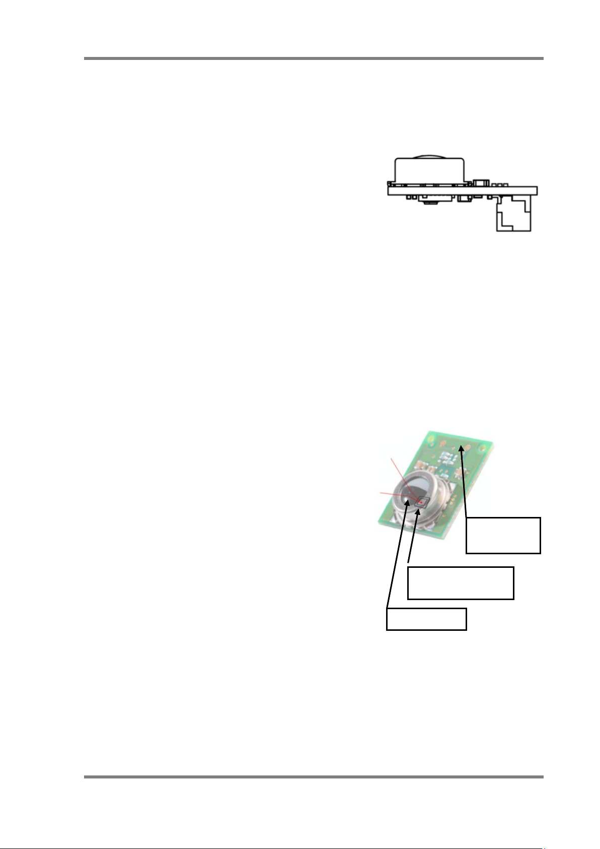
Fig. 1. Exterior of Module (Reference)
Fig. 2. Module Configuration
1 Overview
This user manual describes the usage procedures, precautions, and other information regarding
D6T-series MEMS Thermal Sensors. This document also serves as a supplement to the product
catalog. Reference this document together with the product catalog when using this device.
2 Structure (Part Configuration)
The D6T series of MEMS Thermal Sensors consists of a
small circuit board onto which a silicon lens, thermopile
sensor, specialized analog circuit, and logic circuit for
conversion to a digital temperature value are arranged.
This product only requires one connector to connect
these modules.
3 External Dimensions
This product features a circuit board size of 14 mm x 18 mm. An even more compact size of
11.6 mm x 12 mm is also available. Refer to the product catalog for more information on
mounting areas and positioning of the circuit board. Refer to Chapter 6 for more information on
compatible connectors.
4 Principles of Operation
The following list describes an overview of the measuring
operation of the MEMS Thermal Sensors.
· The silicon lens focuses radiant heat (far-infrared
rays) emitted from objects onto the thermopile sensor
in the module. (*1)
· The thermopile sensor generates electromotive force
in accordance with the radiant energy (far-infrared
rays) focused on it.
· The values of this electromotive force and the internal
thermal sensor are measured. Then, the device
calculates the measured value (temperature of the
(Interior side)
Thermopile sensor
object) via an interpolation calculation that compares
the measured values with an internally stored lookup
Silicon lens
table. (*2)
· The measured value is output via the I2C bus, and read
using a host system.
(*1) The D6T-1A-01/02 models use a silicon filter.
(*2) D6T-1A-01/D6T-1A-02/D6T-8L-09 use a temperature conversion circuit in the ASIC
to calculate measured values (temperatures of objects).
(Back side)
I2C connector
D6T MEMS Thermal Sensors User’s Manual (A284) 2
Pyroelectric Sensor
Thermal Sensor
FOV (16-channel)
50%
FOV and XY-axis sensitivity characteristics
5 Product Features
MEMS Thermal Sensors measure the surface temperature of objects. The D6T-44L-06 model
features 16 channels in a 4 x 4 arrangement. The D6T-8L-09 features a single 8-channel array.
The D6T-1A-01/-02 models feature a 1-channel sensor chip. The module has been optimized by
placing the specialized downstream processing circuit adjacent to the sensor chip to achieve
low-noise temperature measurements.
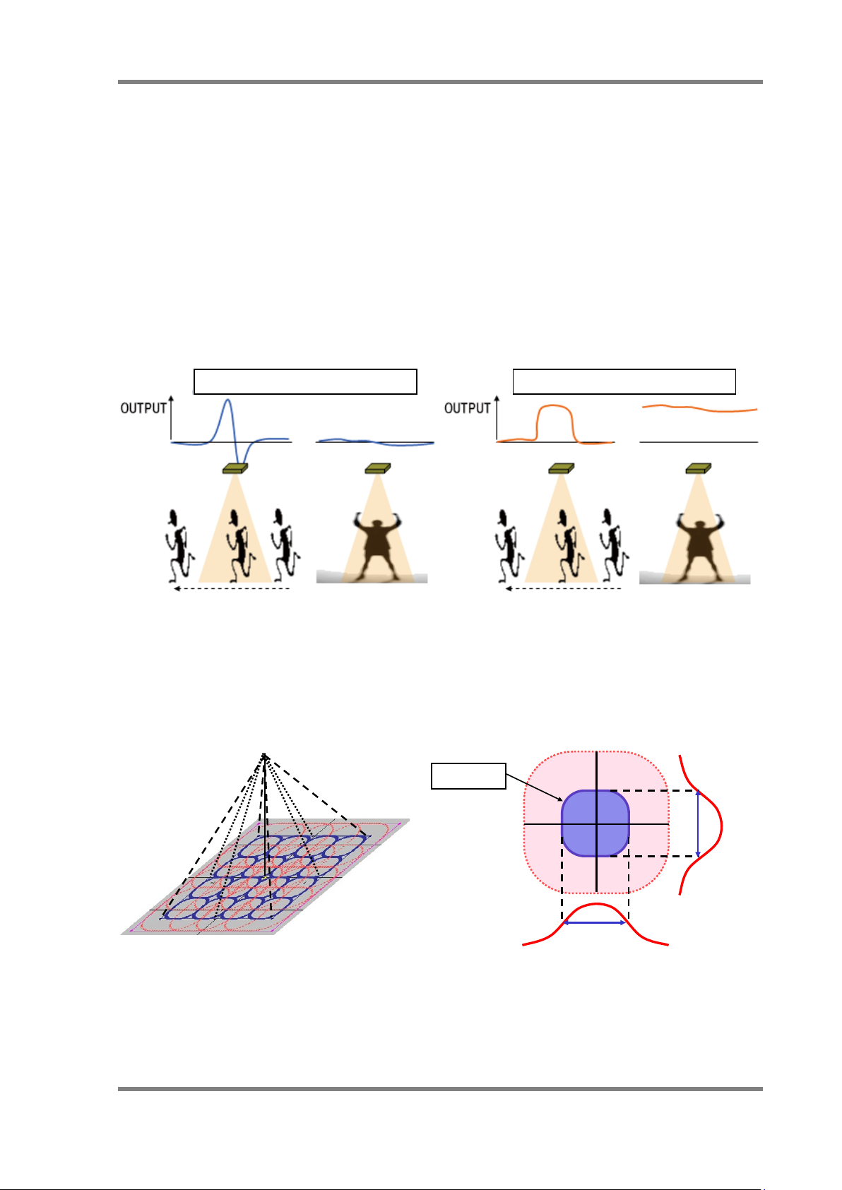
Using our MEMS Thermal Sensors as a human sensor eliminates the problems in using
conventional pyroelectric sensors to detect the presence of people. Pyroelectric sensors can be
used to detect movement of people based on the principle of detecting change components of
infrared rays, but the measurement signal is lost during times of no movement. Conversely,
Thermal Sensors continue to generate a measurement signal during times of no movement.
(a) Output of pyroelectric sensor (b) Output of Thermal Sensor
Fig. 3. Difference Between MEMS Thermal Sensor and Pyroelectric Sensor
MEMS Thermal Sensors feature a silicon lens optically designed to have specific sensitivity
characteristics. Our Thermal Sensors feature the same field of view (FOV) at a maximum
sensitivity of 50% as general sensors.
FOV
Maximum sensitivity of
(b)
(a) Conceptual illustration of D6T-44L-06
Conceptual illustration of single-element
Fig. 4. Field of View (FOV) and Sensitivity Characteristics Illustrations
3 D6T MEMS Thermal Sensors User’s Manual (A284)
Distance: Close <<<<< Far
The sensitive areas of elements are wider than the FOV-specification width. If the size of the
measured object is smaller than the sensitive area of an element, the background temperature of
objects other than the intended object will become a factor.
Our Thermal Sensors use a reference heat source (a blackbody furnace) to correct temperature
values. However, note that differences in emissivity due to composition of measured objects, surface
shape, and the occupancy ratio of objects within sensitive areas all affect temperature values.
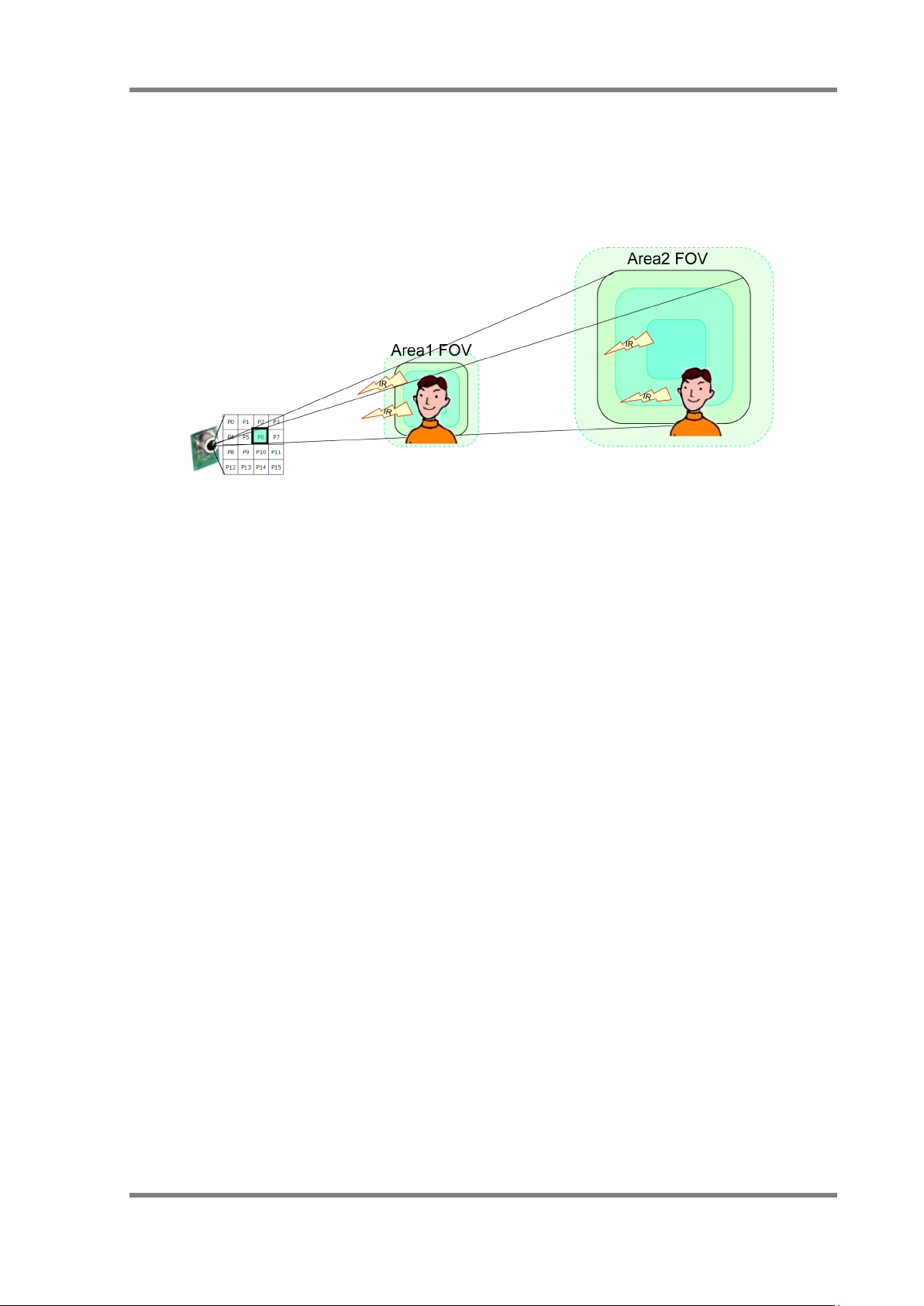
Fig. 5. Distance as Factor of Fluctuations in Temperature Values
The measurable area (FOV) enlarges as the distance between the measured object increases.
The occupancy ratio of objects (people) in the FOV reduces as the distance increases. For this
reason, as the distance increases, the temperature values become more a representation (level of
influence) of the background temperature than the temperature of the intended object (people). In
other words, to correctly measure temperature of the intended objects, the measured object must
be sufficiently larger than the FOV area.
Using a MEMS Thermal Sensor as a human sensor is limited to close-distance applications for
simple determination of temperature value only. To increase the detection distance, determination
accuracy must be improved through software processing that factors temporal changes, position
of heat sources, human behavior information, and so on.
D6T MEMS Thermal Sensors User’s Manual (A284) 4
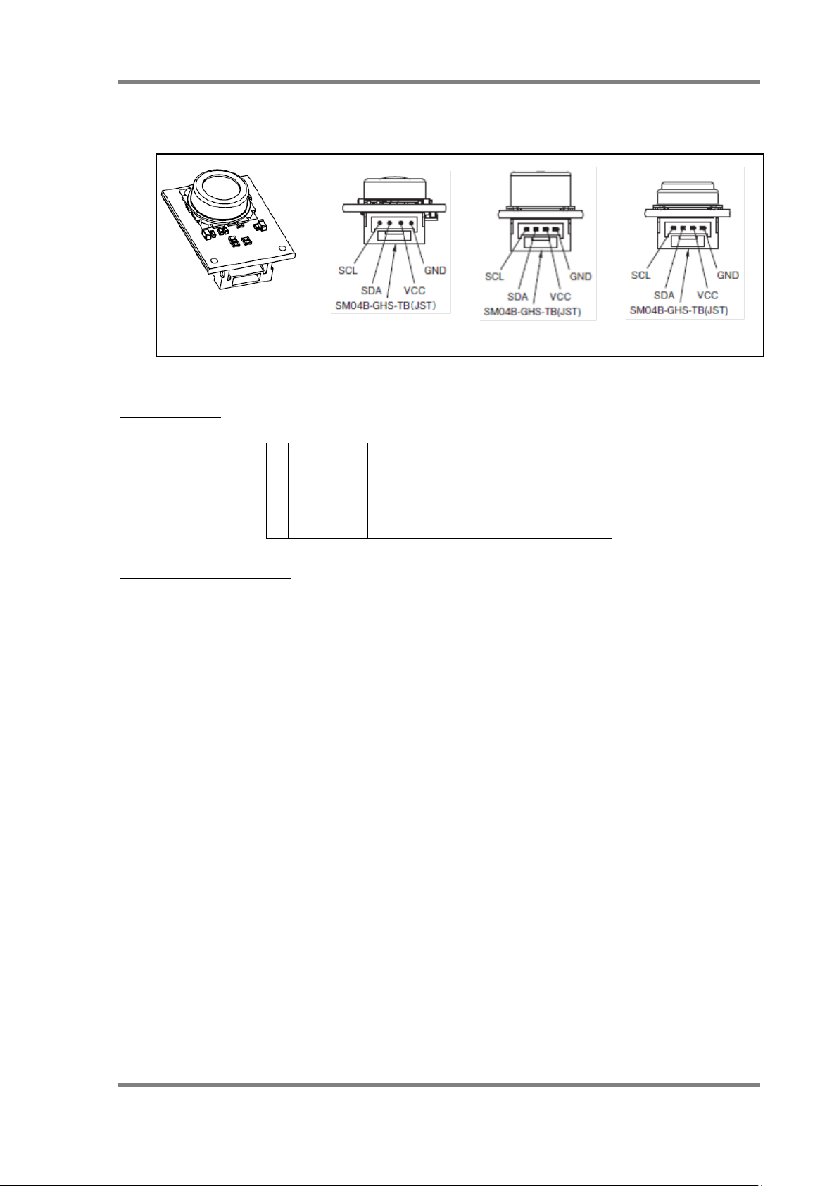
1
GND
GND power supply pin
D6T-8L-09
D6T-1A-01 / -02
D6T-44L-06
6 Usage Procedure
6.1 Connectors
Connector Pins
2 VCC VCC power supply pin (5 V ±10%)
3 SDA I2C (5 V) data
4 SCL I2C (5 V) clock
Fig. 6. Product Exterior (Reference)
Table 1. Connector Pin Table
Connector Parts Materials
Connector part model: SM04B-GHS-TB (JST)
Contact: SSHL-002T-P0.2 (JST)
Housing: GHR-04V-S (JST)
The lens height and circuit board size varies by model. Refer to the product catalog for more
information on dimensions. Use a 4-pin connector as described above to connect this module to
systems.
5 D6T MEMS Thermal Sensors User’s Manual (A284)
D6T
VCC
SDA
SCL
GND
VDD
SDA
SCL
GND
MCU
R
R
5V3V
D6T
VCC
SDA
SCL
GND
VDD
SDA
SCL
GND
MCU
R
R
I2C
Level
Translating
R
R
5V
Ex. PCA9517
Pull-up Resistance Values
3 k to 10 kΩ.)
D6T
VCC
SDA
SCL
GND
VDD5
SDA
SCL
GND
MCU
Power
circuit
5V
GND
R
I2C
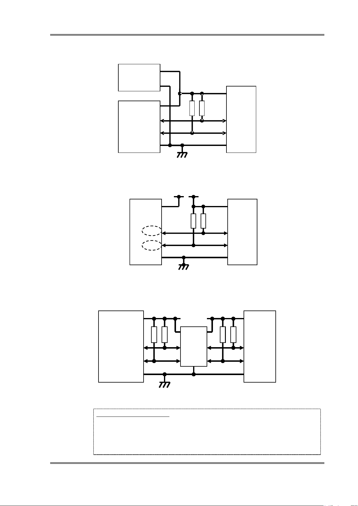
6.2 Example Electrical Connections
Scenario 1: 5 V MCU Direct Connection (Same voltage as the microcontroller power supply)
R
Fig. 7 (a) Connecting to 5 V Microcontroller
Scenario 2: 3 V MCU (I2C port is 5 V fault tolerant)
Scenario 3: Using an I2C Level Converter
(Not a 5 V fault tolerant specification, or other devices are also connected to the 3 V I2C bus)
D6T MEMS Thermal Sensors User’s Manual (A284) 6
Fig. 7 (b) 5 V Fault Tolerant Specification
level
converter
Fig. 7 (c) Using a Level Converter
Values will be adjusted per user calculations of specific usage conditions such
as wiring capacitance.
(Check the I2C specifications. In most cases, the range is set to approximately
MCU
R
FF
OpenDrain
SDA
SCL
R
FF
OpenDrain
SDA
SCL
D6T
VCC
SDA
SCL
GND
VDD
SDA
SCL
GND
MCU
R
R
I2C bus
switch
R
R
5V
R
R
D6T
VCC
SDA
SCL
GND
:
SDA 0
SCL 0
SDA x
SCL x
SDA 1
SCL 1
SDA 2
SCL 2
I2C
bus
IC
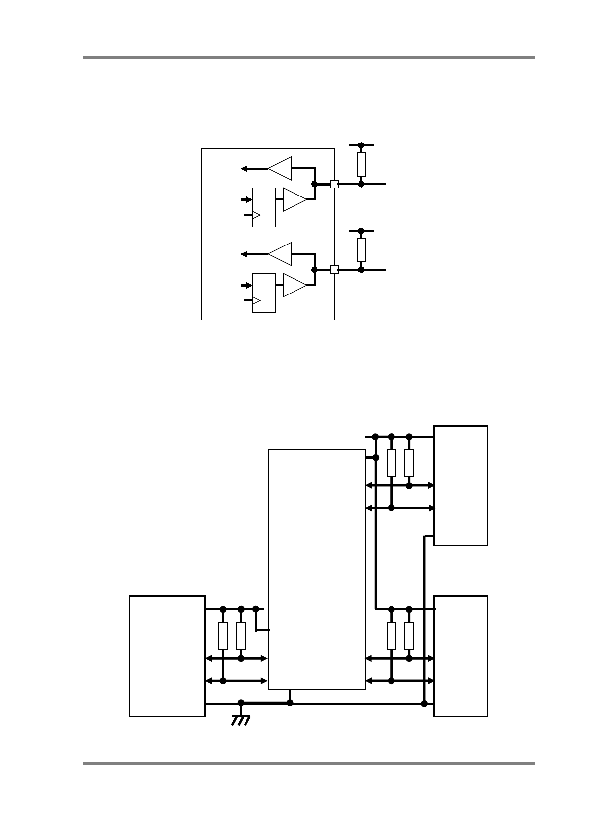
Scenario 4: Using a Bidirectional Open-Drain GPIO Terminal and Performing I2C
Communication Processing in Software
(MCU does not have built-in I2C functionality)
* Note: Clock stretch support is required (refer to section 6.6).
Fig. 7 (d) Using a GPIO Terminal
Scenario 5: Using an I2C Bus-Switching IC (Connecting multiple D6T sensors)
(This sensor cannot change slave addresses)
* Most bus-switching ICs also have power voltage conversion functionality.
-switching
7 D6T MEMS Thermal Sensors User’s Manual (A284)
Fig. 7 (e) Using an I2C Bus-Switching IC
 Loading...