

Page 1

ASC-DE-121119-3E
EQUO Series
Air Flow Station
D6FZ-FGX21
Air Flow Sensor
D6FZ-Series
User’s Manual
Page 2

i
Included Manuals (Print)
Instruction Sheet
Describes the information to ensure the safe and proper use of the product, and information
regarding ratings, performance and installation.
Startup Guide
Describes the basic procedures including the package content check, assembly, setting
operation, recording operation and data display.
Manuals available from Website (PDF data)
User's Manual (This document)
Describes information to ensure the safe and proper use of the product
Describes package content items and detailed procedures for assembly, setting operation,
recording operation and data display
Product specifications
Other necessary information required to use the D6FZ-FGX21 Air Flow Station and Air Flow
Sensors.
PC Software "User's Manual"
Describes the information on the functions and operation of the PC software.
Introduction
Thank you for purchasing an EQUO Series D6FZ-FGX21 Air Flow Station and D6FZ-Series Air Flow Sensor.
This manual describes the information on the functions, performance and usage required to use the Power
Sensor Station.
Please observe the following when using the Air Flow Sensor and Air Flow Station:
・ This product must be handled by specialists with electrical knowledge.
・ Read this User's Manual thoroughly to be familiar with the product beforehand for correct operation.
・ Keep this manual for future reference.
Trademarks
・Microsoft and Windows are registered trademarks or trademarks of Microsoft Corporation in the United
States and other countries.
・Other company names and product names are registered trademarks or trademarks of each company.
Manual Types and Their Usage
The major contents of the manuals are shown below. Select and read the manual according to your need.
Page 3

ii
Terms and Conditions Agreement
Warranties.
(a) Exclusive Warranty. Omron’s exclusive warranty is that the Products will be free from defects
in materials and workmanship for a period of twelve months from the date of sale by Omron (or
such other period expressed in writing by Omron). Omron disclaims all other warranties, express
or implied.
(b) Limitations. OMRON MAKES NO WARRANTY OR REPRESENTATION, EXPRESS OR
IMPLIED, ABOUT NON-INFRINGEMENT, MERCHANTABILITY OR FITNESS FOR A
PARTICULAR PURPOSE OF THE PRODUCTS. BUYER ACKNOWLEDGES THAT IT ALONE
HAS DETERMINED THAT THE PRODUCTS WILL SUITABLY MEET THE REQUIREMENTS OF
THEIR INTENDED USE.
Omron further disclaims all warranties and responsibility of any type for claims or expenses based
on infringement by the Products or otherwise of any intellectual property right.
(c) Buyer Remedy. Omron’s sole obligation hereunder shall be, at Omron’s election, to (i) replace
(in the form originally shipped with Buyer responsible for labor charges for removal or
replacement thereof) the non-complying Product, (ii) repair the non-complying Product, or (iii)
repay or credit Buyer an amount equal to the purchase price of the non-complying Product;
provided that in no event shall Omron be responsible for warranty, repair, indemnity or any other
claims or expenses regarding the Products unless Omron’s analysis confirms that the Products
were properly handled, stored, installed and maintained and not subject to contamination, abuse,
misuse or inappropriate modification. Return of any Products by Buyer must be approved in
writing by Omron before shipment. Omron Companies shall not be liable for the suitability or
unsuitability or the results from the use of Products in combination with any electrical or electronic
components, circuits, system assemblies or any other materials or substances or environments.
Any advice, recommendations or information given orally or in writing, are not to be construed as
an amendment or addition to the above warranty.
See http://www.omron.com/global/ or contact your Omron representative for published information.
Limitation on Liability; Etc.
OMRON COMPANIES SHALL NOT BE LIABLE FOR SPECIAL, INDIRECT, INCIDENTAL, OR
CONSEQUENTIAL DAMAGES, LOSS OF PROFITS OR PRODUCTION OR COMMERCIAL
LOSS IN ANY WAY CONNECTED WITH THE PRODUCTS, WHETHER SUCH CLAIM IS
BASED IN CONTRACT, WARRANTY, NEGLIGENCE OR STRICT LIABILITY.
Further, in no event shall liability of Omron Companies exceed the individual price of the Product
on which liability is asserted.
Suitability of Use.
Omron Companies shall not be responsible for conformity with any standards, codes or
regulations which apply to the combination of the Product in the Buyer’s application or use of the
Product. At Buyer’s request, Omron will provide applicable third party certification documents
identifying ratings and limitations of use which apply to the Product. This information by itself is not
sufficient for a complete determination of the suitability of the Product in combination with the end
product, machine, system, or other application or use. Buyer shall be solely responsible for
determining appropriateness of the particular Product with respect to Buyer’s application, product
or system. Buyer shall take application responsibility in all cases.
NEVER USE THE PRODUCT FOR AN APPLICATION INVOLVING SERIOUS RISK TO LIFE OR
PROPERTY OR IN LARGE QUANTITIES WITHOUT ENSURING THAT THE SYSTEM AS A
WHOLE HAS BEEN DESIGNED TO ADDRESS THE RISKS, AND THAT THE OMRON
PRODUCT(S) IS PROPERLY RATED AND INSTALLED FOR THE INTENDED USE WITHIN
THE OVERALL EQUIPMENT OR SYSTEM.
Programmable Products.
Omron Companies shall not be responsible for the user’s programming of a programmable
Product, or any consequence thereof.
Performance Data.
Data presented in Omron Company websites, catalogs and other materials is provided as a guide
for the user in determining suitability and does not constitute a warranty. It may represent the
result of Omron’s test conditions, and the user must correlate it to actual application requirements.
Actual performance is subject to the Omron’s Warranty and Limitations of Liability.
Page 4

iii
Change in Specifications.
Product specifications and accessories may be changed at any time based on improvements and
other reasons. It is our practice to change part numbers when published ratings or features are
changed, or when significant construction changes are made. However, some specifications of
the Product may be changed without any notice. When in doubt, special part numbers may be
assigned to fix or establish key specifications for your application. Please consult with your
Omron’s representative at any time to confirm actual specifications of purchased Product.
Errors and Omissions.
Information presented by Omron Companies has been checked and is believed to be accurate;
however, no responsibility is assumed for clerical, typographical or proofreading errors or
omissions.
Page 5
iv
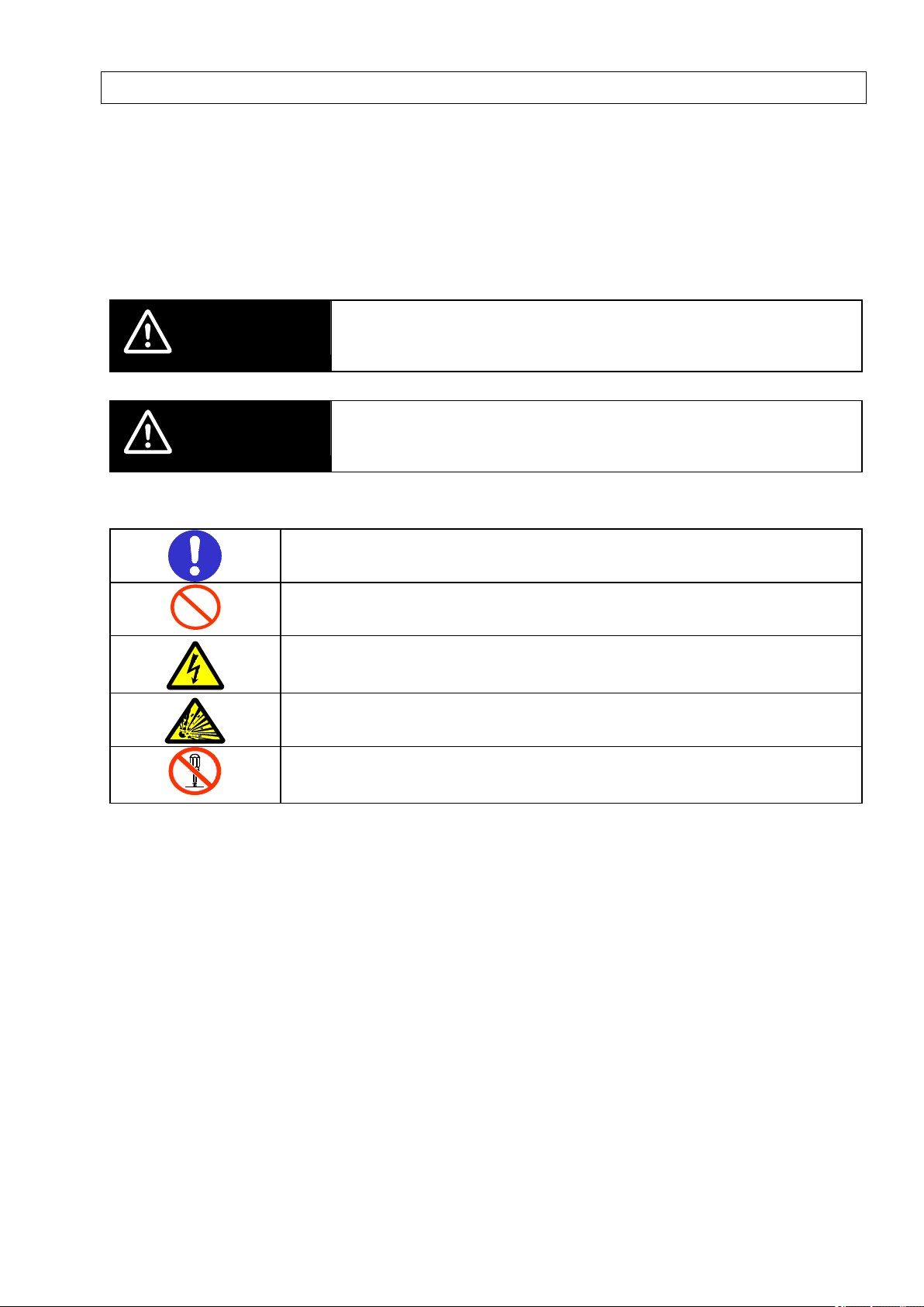
WARNING
Indicates a potentially hazardous situation which, if not avoided, will result in
minor or moderate injury, or may result in serious injury or death.
Additionally there may be significant property damage.
CAUTION
Indicates a potentially hazardous situation which, if not avoided, may result
in minor or moderate injury or in property damage.
●Mandatory Requirement
Indicates a general mandatory requirement.
●Prohibition
Indicates general prohibition.
●Electric Shock Warning
Warns against an electric shock under specific conditions.
●Explosion Warning
Warns against an explosion under specific conditions.
●Disassembly Prohibition
Indicates the possibility of accidents such as an electric shock caused by unit
disassembly.
Precautions on Safety
●Meanings of Signal Words
For the safe operation of D6FZ-FGX21 Air Flow Station and D6FZ-Series of Air Flow Sensors and this
operation manual indicates the precautions by using the following marks and symbols. The precautions given
here contain important information related to safety, and therefore must be observed.
The marks and symbols for the safety precautions are as follows:
●Meaning of Precaution Symbols
Page 6
v
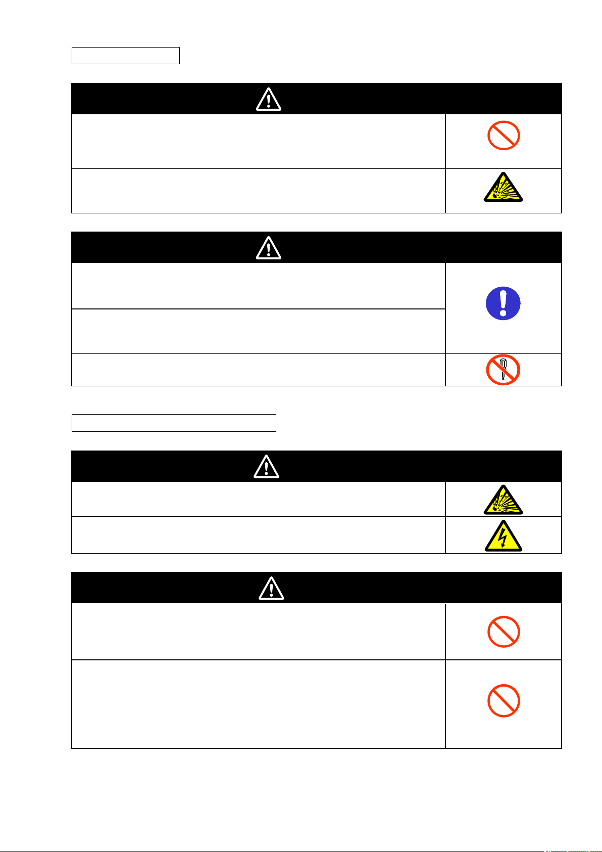
WARNING
The mounting magnets (separately sold) for the product have strong
magnetism. If the product is mounted using these magnets, anyone wearing a
heart pacemaker must not operate the product; or the product must not be in
proximity of such a person.
This product contains a lithium battery. Serious injury may occur due to fire or
explosion. Do not attempt to disassemble the product, deform it by applying
pressure, heat it in a high temperature (100℃ or more), or burn it for disposal.
CAUTION
Tighten the terminal screws at a recommended torque: 0.69 to 0.88N・m.
Make sure that the screws are not slanted away from the center after
tightened.
A minor or moderate injury or property damage may occur due to explosion.
Do not use the product in an environment containing an inflammable or
explosive gas.
An electric shock or minor injury as well as fire or unit malfunction may
occur. Do not attempt to disassemble, repair or modify the product.
WARNING
The use of flammable gases may cause explosion. Do not use the product
with flammable gases.
An electric shock may occur. Do not connect to an AC power source.
CAUTION
Injury may occur due to explosion. Flow rate and pressure must be within
the range of use.
Don’t measure other than air and nitrogen gas.
<D6FZ-FGT>
If water drop, oil, mist and dust flow in the body, it may mismeasurement
and destruction. Use clean fluid. Dust and mist can affect the characteristics
of Sensor or damage the sensor. Install a filter and mist separator on the
upstream tube. Moreover, install an air flow sensor after removing the dust
remaining in pipe by something like air blow.
Air Flow Station
●Warning Indications
Air Flow Sensor (D6FZ-Series)
●Warning Indications
Page 7

vi
Precautions for Safe Use
Observe the following precautions to ensure safe operation:
Air Flow Station
・ Do not install the product in the places subject to exposure to water, oil, or chemical splashes.
・ Do not use the product for the safety circuits in nuclear power or life-critical applications.
・ When disposing of the product, treat as industrial waste.
・ Do not let the product drop or subject it to a shock, which may cause its damage or malfunction. Use
screws to secure the product when mounting it on the wall. Stop using the product if it has been applied
with a strong impact.
・ When inserting or removing an SD memory card, securely hold the product to prevent it from dropping,
which may cause a damage. Do the same when inserting or detaching an alarm output cable or
connector.
・ Do not bring the product close to magnetic products (e.g. magnetic cards), sensitive electronics
equipment (e.g. computers or clocks), when the product is attached with the mounting magnets.
・ Small pieces may be chipped off the mounting magnets when they are attracted to the surface. Make
sure the pieces do not enter the eyes. Consult a medical doctor if this happens.
・ When using the mounting magnets to install the product, take caution not to allow a finger to be caught
between the product(s) and the magnetic surface.
・ Do not install the product at a high place when using the mounting magnets.
・ Apply an appropriate load to the alarm output terminals to prevent possible smoking.
・ If liquid crystal leaks due to a damage to the LCD panel, take caution not to allow it to contact your skin,
to be inhaled or swallowed. If it has contacted your skin or entered your mouth, seek medical attention.
・ Take anti-static electricity measures (e.g. touching grounded metal object) when handling the product.
Air Flow Sensor (D6FZ-Series)
<D6FZ-Series>
・ Do not use the power supply that exceeds rated voltage.
・ Use a DC power supply unit provided with anti-voltage design (safety extra low voltage circuit) to supply
power to the product.
・ Do not connect the power supply in reverse.
・ Do not short-circuit outputs.
・ The attached connection cable is only for Air Flow Station (D6FZ-FGX). Do not connect with other
device.
・ Do not use the Sensor with any gases or liquids other than specified in this document.
・ Be sure to secure the Sensor with the stipulated torque.
・ Do not install the Sensor in a location where strong compressive force or tensile force applied to the
Sensor.
・ Do not attempt to disassemble, repair, or modify this product.
・ When disposing of the product, treat as industrial waste.
Page 8

vii
・ Do not let the product drop or subject it to a shock. Stop using the product if it has been applied with a
strong impact.
・ Don't connect a power supply to RS-485 communications line. There is fear of product damage.
・ Fix with only the conduit part when mounting pipe, or the product might damage.
<D6FZ-FGS1000>
・ Do not ground Brown colored wire (DC24V). As the enclosure is connected to 0V inside circuit, it is
short-circuited with your device FG.
・ Be sure to ground Blue colored wire + shield (0V) of single-end wire cable (D6FZ-JDA).
<D6FZ-FGT>
・ Don't touch the current plate in the flow channel, or fingers might be injured.
・ Connect blue colored wire (0V) with the shield line of a single-end line cable (model D6FZ-JDA, sold
separately). The shield line and the blue colored wire (0V) is connected inside form D6 FZ-JDA.
Page 9
viii
Precautions for Correct Use
Air Flow Station
1. Avoid installing the product in the following places:
・ Places exceeding the rated ambient temperature
・ Places exposed to extreme temperature changes (where condensation occurs)
・ Places subject to relative humidity exceeding the rated humidity range
・ Places subject to corrosive or flammable gases
・ Places subject to mist, droplets, coarse particles, fiber, salt, metal dust, or large amount of particles
・ Places subject to direct shock or vibration
・ Places subject to direct sunlight
・ Places subject to exposure to water, oil, or chemical splashes
・ Places subject to strong magnetic field or electric field
・ Outdoors
2. Wiring
・ Wire the product cable separately from high-voltage or power lines. Placing them in the same wiring or
the same duct may cause induction, resulting in the product malfunction or damage.
・ Make sure that the I/O terminals are inserted or removed with the power turned OFF. Doing this with the
power ON may result in a failure.
3. Mounting screw hole
・ The screw holes provided on the product are M3 and 4 mm deep. Do not screw deeper than 4 mm,
which may damage the product.
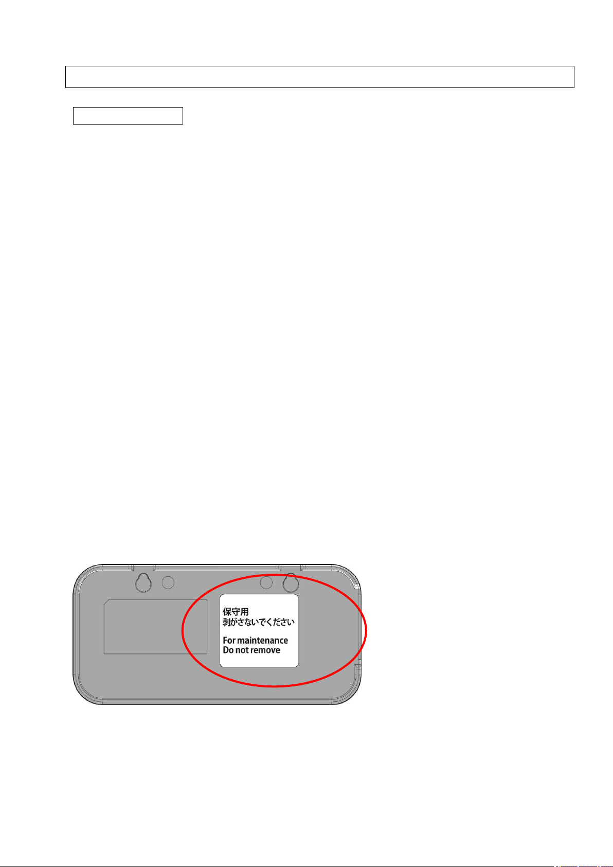
4. Do not open the unit rear cover. (No battery terminal is provided.)
Page 10
ix
Air Flow Sensor (D6FZ-Series)
<D6FZ-Series>
1. Do not install the product in locations subjected to the following conditions:
・ Ambient temperature outside the rating
・ Ambient humidity outside the rating
・ Altitude of 2,000 m or higher above sea level
・ Presence of corrosive or flammable gases
・ Presence of salt or iron particles
・ Direct vibration or shock
・ Outdoors or direct sunlight
・ Water, oil, or chemical fumes or spray, or mist atmospheres
・ Presence of strong magnetic field, electric field or charged object
2. Power Supply and Wiring
・ If the power supply line is subject to surges, connect a surge absorber that meets the conditions of the
operating environment.
・ Be sure to check the polarity before connecting a power supply line/output line. Do not apply over-rated
voltage.
・ Do not short circuit the power supply when connecting a power supply line.
・ Do not use the product with current higher than the rating when connecting an output line.
・ Lay the product cable away from any high-voltage cable or power line. If laid in the same conduit or duct,
induction noise from them may cause malfunction or breakdown of the product.
・ Do not insert or remove a connector, etc. with power supply applied.
・ When using analog output or control output, cable length needs to be less than 30 m.
・ When using with an Air Flow Station make the power supply voltage 24VDC.
・ When using RS-485 communication and cable length is more than 30m, be sure to ground blue
colored wire (0V) and shield.
3. Installation
・ When mounting the product, be careful not to get a finger caught in it.
<D6FZ-FGS1000>
・ Do not use the product as scaffolding.
・ Take caution not to mount the status indicator downward. Doing so may result in Malfunction.
<D6FZ-FGT>
・ Be sure to mount the body horizontally, otherwise the detection accuracy might be worse.
・ Don't mount the body facing the control panel downward. Otherwise, the mist and dust in the pipe
accumulates and it might cause breakdown.
Page 11

x
How to Read This Manual
■Symbols Used in this Manual
Menu items that are displayed on the screen, and windows, dialog boxes and other GUI elements displayed
on the PC are indicated enclosed by brackets "[ ]".
■Marks Used in this Manual
Important:Indicates essential information on the product operation and functions, which requires special
attention or caution.
Note:Shows operational tips or related useful information.
Page 12

xi
Table of Contents
Introduction ........................................................................................................................................................ i
Table of Contents ............................................................................................................................................. xi
1. Product Overview .................................................................................................................................. 1-1
1.1 Features and Functions ................................................................................................................... 1-1
1.2 Configuration .................................................................................................................................... 1-3
1.2.1 Single Air Flow Sensor Unit Connection ................................................................................... 1-4
1.2.2 Local Connection ...................................................................................................................... 1-4
1.2.3 Network Connection ................................................................................................................. 1-4
1.3 Multi-point Air Flow Measurement .................................................................................................... 1-5
1.4 Setup and Operation Procedure ...................................................................................................... 1-6
1.4.1 Single Air Flow Sensor Unit Operation ..................................................................................... 1-6
1.4.2 Standalone Operation ............................................................................................................... 1-7
1.4.3 Operation via Network .............................................................................................................. 1-8
2. Part Name and Function ....................................................................................................................... 2-1
2.1 Air Flow Sensor (D6FZ-FGS1000) ................................................................................................... 2-1
2.1.1 Display Unit ............................................................................................................................... 2-1
2.1.2 Control Unit ............................................................................................................................... 2-2
2.1.3 Input/Output Specifications ....................................................................................................... 2-3
2.2 Air Flow Sensor(D6FZ-FGT) ............................................................................................. 2-5
2.2.1 Control Panel / Display ............................................................................................................. 2-5
2.2.2 Control panel ............................................................................................................................. 2-5
2.2.3 Input/Output Specifications ....................................................................................................... 2-6
2.3 Air Flow Station (D6FZ-FGX21) ....................................................................................................... 2-7
2.3.1 Display Unit ............................................................................................................................... 2-8
2.3.2 Control Unit ............................................................................................................................... 2-9
2.3.3 Input/Output Specifications ..................................................................................................... 2-10
3. Check and Preparation ......................................................................................................................... 3-1
3.1 Checking the Package Contents ...................................................................................................... 3-1
3.2 Preparing the Required Items .......................................................................................................... 3-1
3.3 Setting and Installation ..................................................................................................................... 3-2
Page 13

xii
3.3.1 Single Air Flow Sensor Unit Operation ..................................................................................... 3-2
3.3.2 Standalone Operation Connecting Air Flow Sensors to Air Flow Station .................................. 3-4
3.4 Overview of PC Software ................................................................................................................. 3-9
3.4.1 Overview ................................................................................................................................... 3-9
3.5 Setting the Measurement Conditions ............................................................................................. 3-10
3.5.1 Settings (FUN Mode Operation) ............................................................................................. 3-10
3.6 Connecting to Network ................................................................................................................... 3-12
3.6.1 Preparation ............................................................................................................................. 3-12
3.6.2 Setting Air Flow Station IP Address ........................................................................................ 3-13
3.6.3 Setting the PC IP Address ...................................................................................................... 3-16
3.6.4 Connecting a LAN Cable ........................................................................................................ 3-25
3.7 Mounting Air Flow Sensor and Air Flow Station ............................................................................. 3-26
3.7.1 Mounting Air Flow Sensor ....................................................................................................... 3-26
3.7.2 Mounting Air Flow Station Unit ................................................................................................ 3-28
3.8 Remotely Setting Air Flow Sensors and Air Flow Station ............................................................... 3-30
4. Setting (Air Flow Station Operation) ................................................................................................... 4-1
4.1 Setting Procedure and Operation Modes ........................................................................................ 4-1
4.2 Settings (FUN Mode Operation) ...................................................................................................... 4-2
4.2.1 List of Setting Items .................................................................................................................. 4-3
4.2.2 Selecting "FUN" Operation Mode ............................................................................................. 4-4
4.2.3 Selecting Items ......................................................................................................................... 4-5
4.2.4 Description of Items .................................................................................................................. 4-6
4.2.5 Changing Air Flow Station Set Value ...................................................................................... 4-14
4.2.6 Changing Air Flow Sensor Set Value ...................................................................................... 4-16
4.3 Settings (THR Mode Operation) .................................................................................................... 4-18
4.3.1 List of Setting Items ................................................................................................................ 4-19
4.3.2 Selecting Operation Mode ...................................................................................................... 4-20
4.3.3 Selecting Items ....................................................................................................................... 4-20
4.3.4 Description of Items ................................................................................................................ 4-21
4.3.5 Changing Set Value ................................................................................................................ 4-22
5. Measurement and Recording (Air Flow Station Operation) .............................................................. 5-1
5.1 Overview .......................................................................................................................................... 5-1
5.2 Selecting Operation Mode ............................................................................................................... 5-1
5.3 Screen Transition in RUN Mode ...................................................................................................... 5-2
5.4 Starting/Stopping Recording ............................................................................................................ 5-5
Page 14

xiii
5.4.1 Starting Recording .................................................................................................................... 5-5
5.4.2 Stopping Recording .................................................................................................................. 5-5
5.4.3 Auto backup and restarting record setting ................................................................................ 5-6
5.5 Outputting File to SD memory card .................................................................................................. 5-6
5.6 Cancelling Alarm .............................................................................................................................. 5-6
6. Appendix ................................................................................................................................................ 6-1
6.1 Error Display List .............................................................................................................................. 6-1
6.2 Character Display List ...................................................................................................................... 6-4
6.3 SD Memory Card Folder Structure ................................................................................................... 6-6
6.4 Calibration ........................................................................................................................................ 6-7
Page 15

1-1
1. Product Overview
1.1 Features and Functions
Air Flow Station
(1) Easy Multi-point Data Acquisition
The D6FZ-FGX21 Air Flow Station combined with the D6FZ- Series Air Flow Sensors
provides the measurement and recording of air flow, pressure and temperature at multiple
points. Individual integrated flow rate values are added to total sums, which can be checked
at operation sites. The Air Flow Station can be connected to up to eight Air Flow Sensor
units, whose momentary and integrated flow rate values can be independently recorded.
Flow rate data acquisition at operation sites now becomes easy, contributing to enhanced
energy-saving efficiency.
(2) Recording to an SD Memory Card
The measured data can be recorded in the Air Flow Station (D6FZ-FGX21). Data recorded
for approx. four hours at 1 second cycle can be accumulated in the internal memory when a
single Air Flow Sensor unit is connected, which enables the Air Flow Station to continue
recording even at an emergency network failure. The Air Flow Station allows its data
accumulated in the internal memory to be output to an SD memory card in CSV format
without stopping measurement, thus making continuous recording for long hours possible.
NOTE: The internal memory can store the data continuously recorded for up to minimum
approx. 30 minutes (at a recording cycle time of 2 seconds, when eight Air Flow Sensor
units are connected). Use an SD memory card for longer time of recording.
1. Product Overview
(3) Network Connection
The measured values obtained from multiple Air Flow Station units in a network can be
acquired to a PC connected via LAN cables by using the PC software (Multi Data Viewer
Light). The individual Air Flow Station and Air Flow Sensor units can be controlled from the
PC to check or change their settings as well as send recording start/stop instruction. (Refer
to the PC software "User's Manual" for details.)
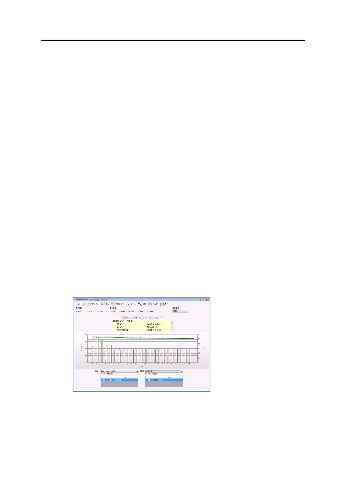
(4) Graph Display and Data Processing Software
The data output to an SD memory card or recorded to a PC through network connection can
be displayed in graphs or processed online by using the PC software. The data items in
different periods can be combined or multiple Air Flow Station data can be displayed
simultaneously side by side on the screen. (Refer to the PC software "User's Manual" for
details.)
(5) Alarm Output
Alarm output terminals are provided on the Air Flow Station. An alarm is output when the
measured air flow rate exceeds the upper limit. This feature provides 'visualization' of the air
flow limit, allowing the operator to quickly handle errors.
Page 16

1-2
Air Flow Sensors (D6FZ-Series)
<D6FZ-FGS1000>
(1) Simultaneous Flow Rate/Pressure/Temperature Measurement
Based on ultrasonic measurement, the Air Flow Sensor provides simultaneous
measurement of flow rate (momentary flow and integrated flow), pressure and temperature.
(2) Flexible Installation Regardless of Location
The capability of measuring air flow mixed with oil or mist provides the installation at various
locations such as behind the curve of a tube.
(3) Analog Output/Pulse Output
The analog output (of standard flow rate/pressure) and pulse output (of integrated flow rate)
from Air Flow Sensors are available for an environment where digital communication is not
possible.
<D6FZ-FGT>
1. Product Overview
(1) Easy to detect air leaks
High measurement accuracy of low flow makes compressed air leaks detection easy.
(2) Flexible Installation Regardless of Location
Sensor equipped with a Flow straightener , the installation at various locations such as
behind the curve of a tube.
(3) Analog Output/Pulse Output
The analog output (of standard flow rate/pressure) and pulse output (of integrated flow rate)
from Air Flow Sensors are available for an environment where digital communication is not
possible.
Page 17
1-3
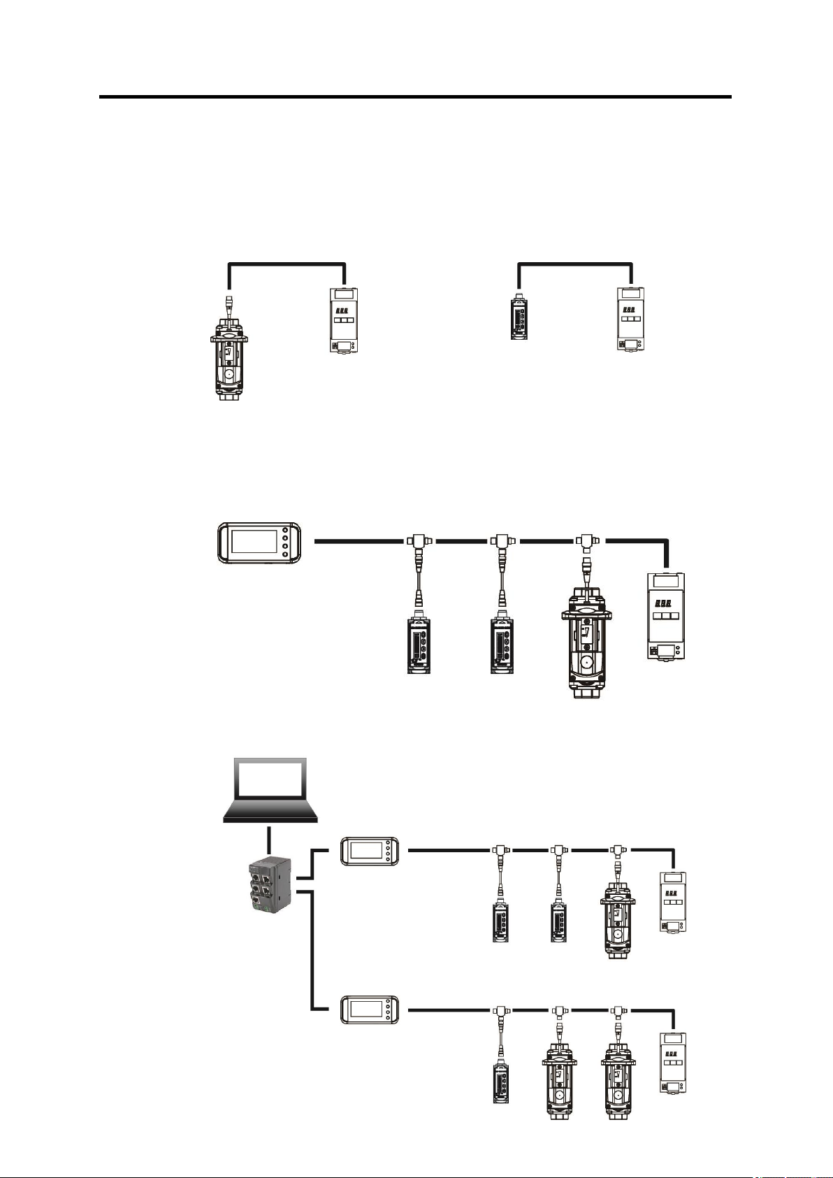
1.2 Configuration
Operation via Network
Standalone Operation
Single Air Flow Sensor Unit Operation
Power Supply
Power Supply
PC
HUB
LAN Cable
Power Supply
Power Supply
HUB
This product can be used in the following three types of configuration.
<D6FZ-FGS1000> <D6FZ-FGT>
1. Product Overview
Page 18
1-4
1.2.1 Single Air Flow Sensor Unit Connection
The usage combined with only a single Air Flow Sensor unit.
<D6FZ-FGS1000>
The measured data can be output from two analog systems or a single pulse system. (A
T-branch connector cannot be used for analog or pulse output.)
<D6FZ-FGT>
The measured data can be output from analog systems, a single pulse system, Judgment
output or unit error output. (A T-branch connector cannot be used for analog, pulse output,
Judgment output or unit error output.)
1.2.2 Local Connection
The Air Flow Station can be used standalone without being connected to a network. The
measured data is recorded in the internal memory, which can be transferred to a PC via an
SD memory card. The recorded data to the SD memory card can be displayed in graphics
using the PC software. (Refer to the PC software "User's Manual" for the details.)
1.2.3 Network Connection
1. Product Overview
Air Flow Stations can be connected to a PC via network. The following operations are
available by using the PC software. (Refer to the PC software "User's Manual" for details.)
(1) Recording the measurement data on PC
By using the PC software, the measurement data can be recorded on PC. The data of the
Air Flow Station is displayed on the graph off-line.
(2) Remote setting / Remote operation via PC
By using the PC software, it is possible to set the setting of the air flow station
(except the IP address setting), and to operate remotely via computer such as recording
Start/Stop.
Page 19

1-5
1.3 Multi-point Air Flow Measurement
・ Connecting multiple Air Flow Sensors to an Air Flow Station as the slave units (up to 8
units) can display the momentary flow rate, pressure and temperature values of the
individual sensor units. The integrated flow rate of the connected sensor units can be
displayed as either of the total sum and the individual rates.
・ The air flow rate, pressure and temperature are constantly displayed while the Air Flow
Sensor is connected to the Air Flow Station.
・ Values measured at multiple points can be logged to a single CSV file record.
※ Pressure and temperature can be measure only by D6FZ-FGS1000.
1. Product Overview
Page 20

1-6
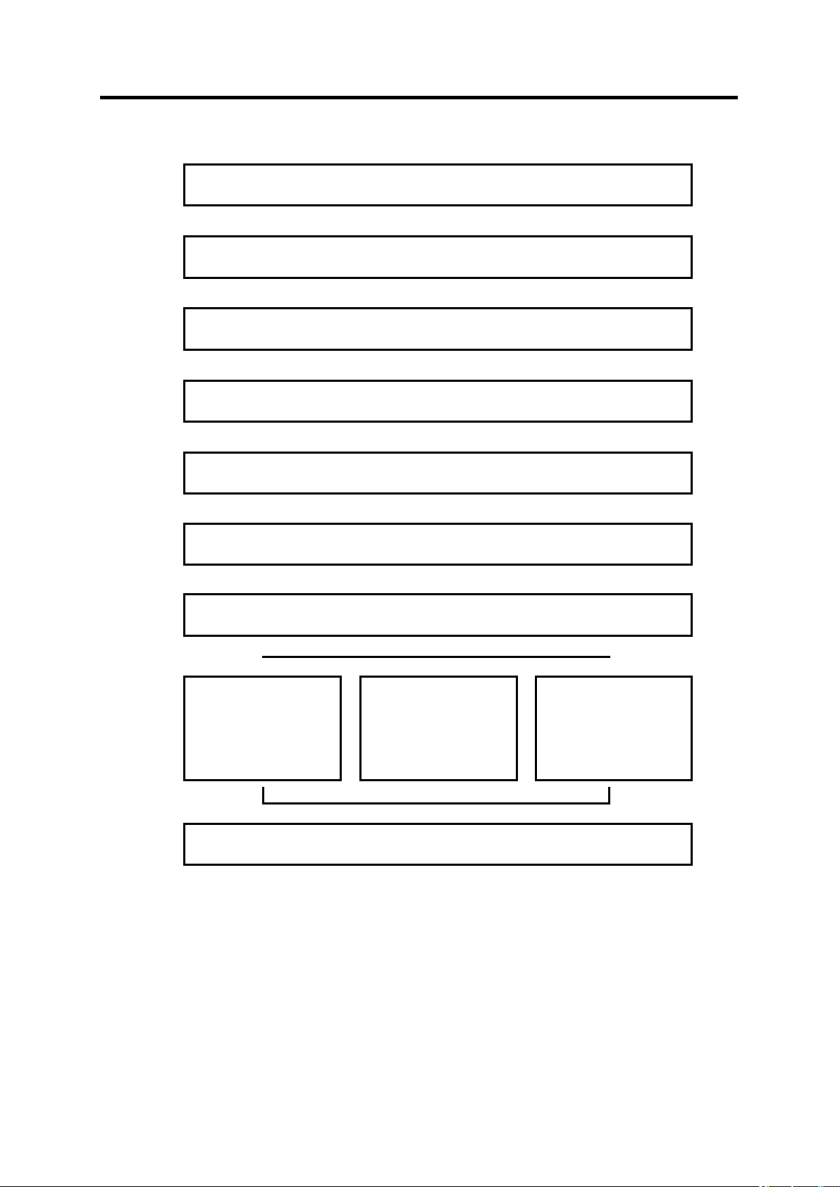
1.4 Setup and Operation Procedure
Check the package contents
⇒3.1 Checking the Package Contents
Check the required items
⇒3.2 Preparing the Required Items
Connect the Air Flow Sensor and power supply
⇒3.3 Setting and Installation
↓
↓
1.4.1 Single Air Flow Sensor Unit Operation
1. Product Overview
Page 21

1. Product Overview
1-7
Check the package contents
⇒3.1 Checking the Package Contents
Check the required items
⇒3.2 Preparing the Required Items
Connect Air Flow Sensor, Air Flow Station, alarm output terminals and power supply
⇒3.3 Setting and Installation
Mount Air Flow Sensors and Air Flow Station
⇒3.7 Mounting Air Flow Sensor and Air Flow Station
Install the PC software
⇒PC Software "User's Manual"
Set the measurement conditions
⇒3.5 Setting the Measurement Conditions
Analyze recorded data
⇒PC Software "User's Manual"
Record data with Air Flow Station
⇒ 5 Measurement and Recording
↓ ↓ ↓ ↓ ↓ ↓ ↓
↓
Make settings using Air Flow Station
⇒ 4 Setting (Air Flow Station Operation)
1.4.2 Standalone Operation
Page 22
1. Product Overview
1-8
Analyze recorded data
⇒PC Software "User's Manual"
Check the package contents
⇒3.1 Checking the Package Contents
Check the required items
⇒3.2 Preparing the Required Items
Connect Air Flow Sensor, Air Flow Station, alarm output terminals and power supply
⇒3.3 Setting and Installation
Connect units to a network
⇒3.6 Connecting to Network
Mount Air Flow Sensors and Air Flow Station
⇒3.7 Mounting Air Flow Sensor and Air Flow Station
Install the PC software
⇒PC Software "User's Manual"
Set the measurement conditions
⇒3.5 Setting the Measurement Conditions
Recording to PC
⇒PC Software "User's
Manual"
Remotely record data
to the Air Flow Station
unit
⇒PC Software "User's
Manual"
Remote setting
⇒3.8 Remotely Setting
Air Flow Sensors and
Air Flow Station
↓ ↓ ↓ ↓ ↓
↓
↓ ↓ ↓
↓
1.4.3 Operation via Network
Page 23
2-1
2. Part Name and Function
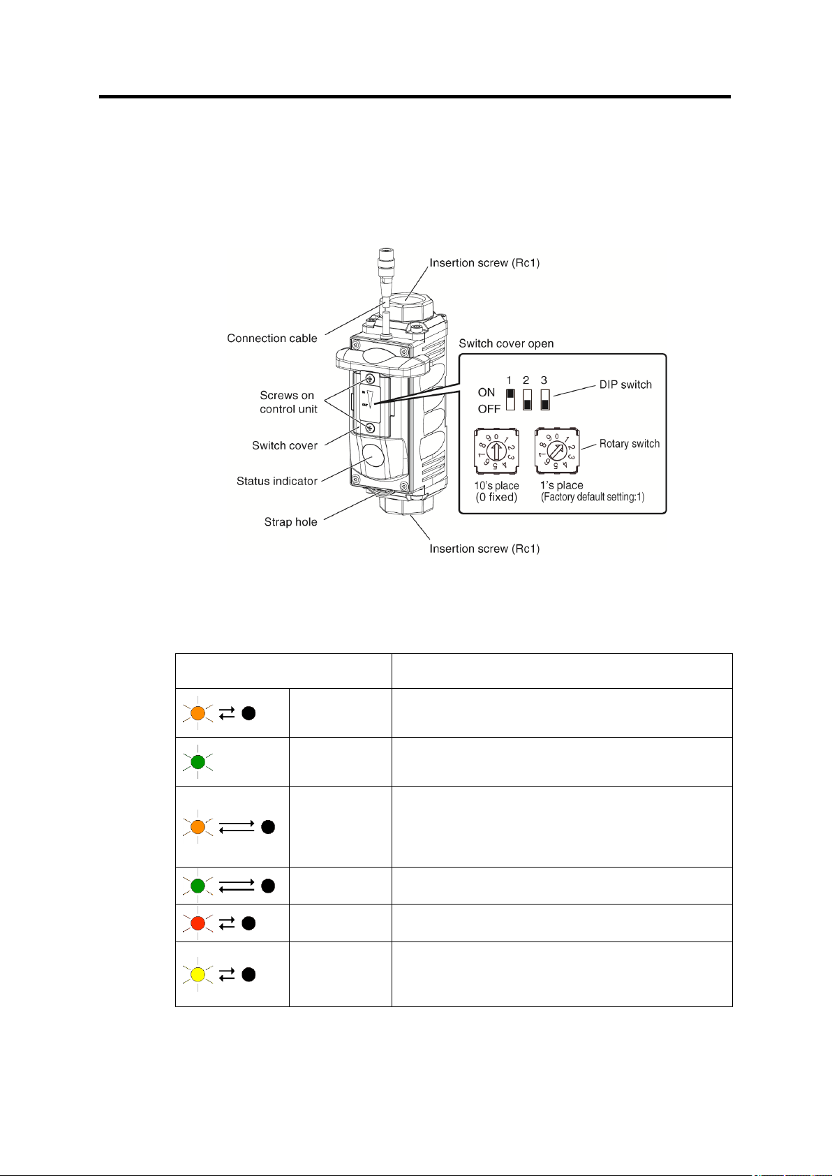
Status Indicator
Definition
Orange Blink
The air flow rate exceeds the upper threshold.
When the factory default: 1000 L/min (std) is
exceeded
Green ON
The air flow rate is normal and between the upper
and lower thresholds
Factory default setting: 0 to 1000 L/min (std)
Orange Slow
Blink
The air flow is rated between the upper threshold
value and zero.
This indication does not happen as long as the
lower threshold value is set to the factory default
(zero).
Green Slow
Blink
The air flow rate is leak detected flow threshold.
Factory default setting: 0 L/min (std)
Deep Orange
Blink
The air flows backward.
Yellow Blink
The unit is in setting process. The status indicator of
the relevant Air Flow Sensor blinks when the
operation mode of the Air Flow Station enters FUN
or THR mode.
2.1 Air Flow Sensor (D6FZ-FGS1000)
2. Part Name and Function
2.1.1 Display Unit
The status indicator colors combined with the indicator status show the air flow status and
errors.
NOTE: The above setting is the factory default. The thresholds for LED indicator can be
changed using the Air Flow Station.
Page 24
2-2
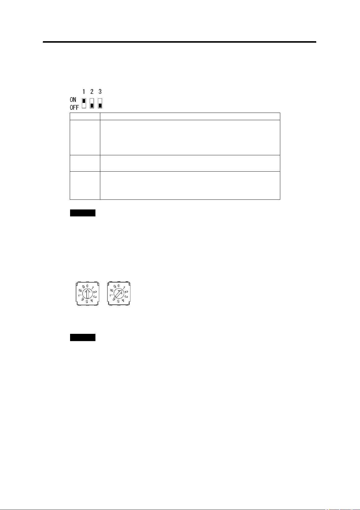
No.
Definition
1
Communication line terminator setting
To use an Air Flow Station (D6FZ-FGX21) or RS-485
communication, turn ON the DIP SW No. 1of the termination Air
Flow Sensor unit in the multi-drop connection.
(Factory default setting: ON)
2
Fixed to OFF (Only used for maintenance. Do not turn it ON)
3
Default communication setting
Use this to reset the settings when changes cannot be tracked
after setting changes.
(Factory default setting: OFF)
2.1.2 Control Unit
(1) DIP SW
Important
DIP SW settings are applied after the unit is reset.
2. Part Name and Function
(2) Rotary SW
Used to specify the IDs of the Air Flow Sensors connected to the Air Flow Station. The
positions from 1 to 8 can be assigned. The ID numbers must be assigned in the ascending
order sequentially without skipping any number.
10's Place 1's Place
(0: Fixed) (Factory default setting: 1)
Important
・Rotary SW settings are applied after the unit is reset.
・1's Place is available 1 to 8, don’t set the ID to 0 and 9.
Page 25
2-3
2.1.3 Input/Output Specifications
Output method
Source current (4-20 mA) method
Output accuracy
±0.1 mA (Except for measurement accuracy)
Load resistance
Max. 270 Ω
Output detail
(*)
Analog Output 1
Standard Flow Rate (L/min (std))
Full-Scale Flow Rate: 1000 L/min (std)( *)
0 L/min(std): 4 mA
1000 L/min(std): 20 mA ( *)
Analog Output 2
Pressure (kPa)
Full-Scale: 1000kPa (1MPa)
0Pa: 4 mA
1Mpa: 20 mA
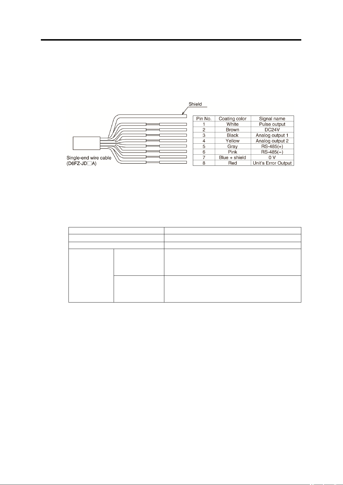
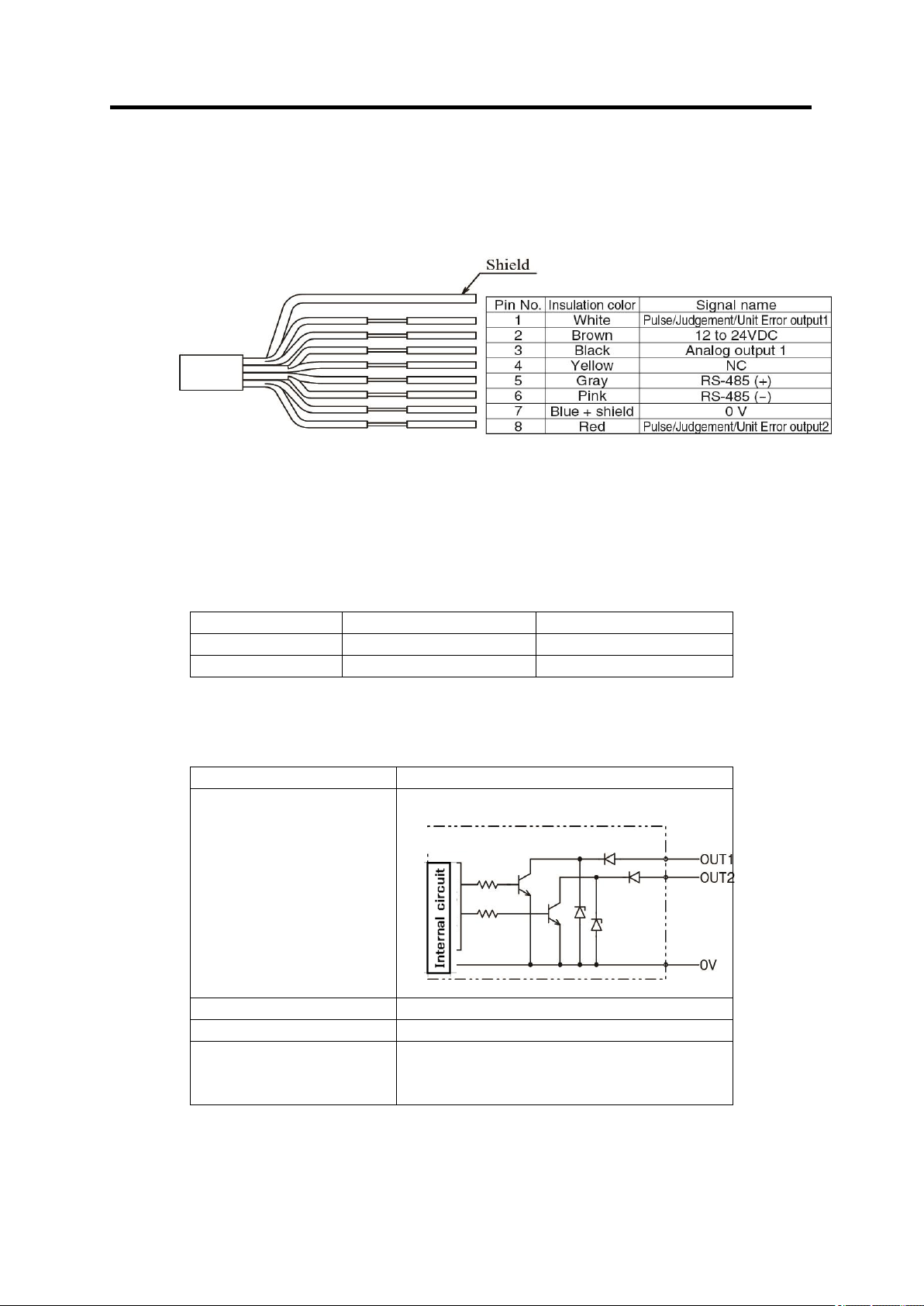
(1) Breakout Cable Wires Color Code (D6FZ-JDA)
The following shows the specifications of the breakout cable connected to the cable
connector socket of an Air Flow Sensor unit.
(2) Analog Output
Analog Output 1 and Analog Output 2 are available for single Air Flow Sensor operation.
The specifications are shown below:
2. Part Name and Function
(*) Can be changed by the D6FZ-FGX21 Air Flow Station.
Page 26
2. Part Name and Function
2-4
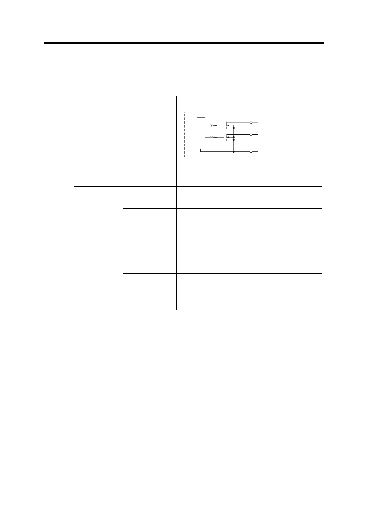
Output method
Nch open drain output
Output Stage Circuit Diagram
Max. rated voltage
24V DC
Max. rated current
50 mA
Residual voltage
Max. 1.5 V
Leakage current
Max. 50 μA
Pulse Output
Output detail
Outputs the measured standard flow rate in the
corresponding unit pulse.
Output unit
1, 10 (Factory default),100, 1000L/P (*)
The pulse output inverts when the half amount of
specified flow rate passes.
(E.g. The output inverts at every 5 L is passed, if
the rate is specified to 10 L/P.)
However, if the frequency increases, the duty may
fluctuate by 20 to 80%.
Unit error
output
Output detail
Turns ON the output when any of the errors below
occurs.
Detection item
Memory error
Ultrasonic wave measurement error
Pressure measurement error
Temperature measurement error
Power supply voltage drop detection
Pulse Output
Unit error output
0 V
Inside D6FZ-FGS1000
Internal Circuit
(3) Pulse Output/Unit Error Output
Pulse Output and Unit Error Output are available for single Air Flow Sensor operation. The
specifications are shown below:
(*) Can be changed by the D6FZ-FGX21 Air Flow Station.
Page 27
2-5
2.2 Air Flow Sensor(D6FZ-FGT)
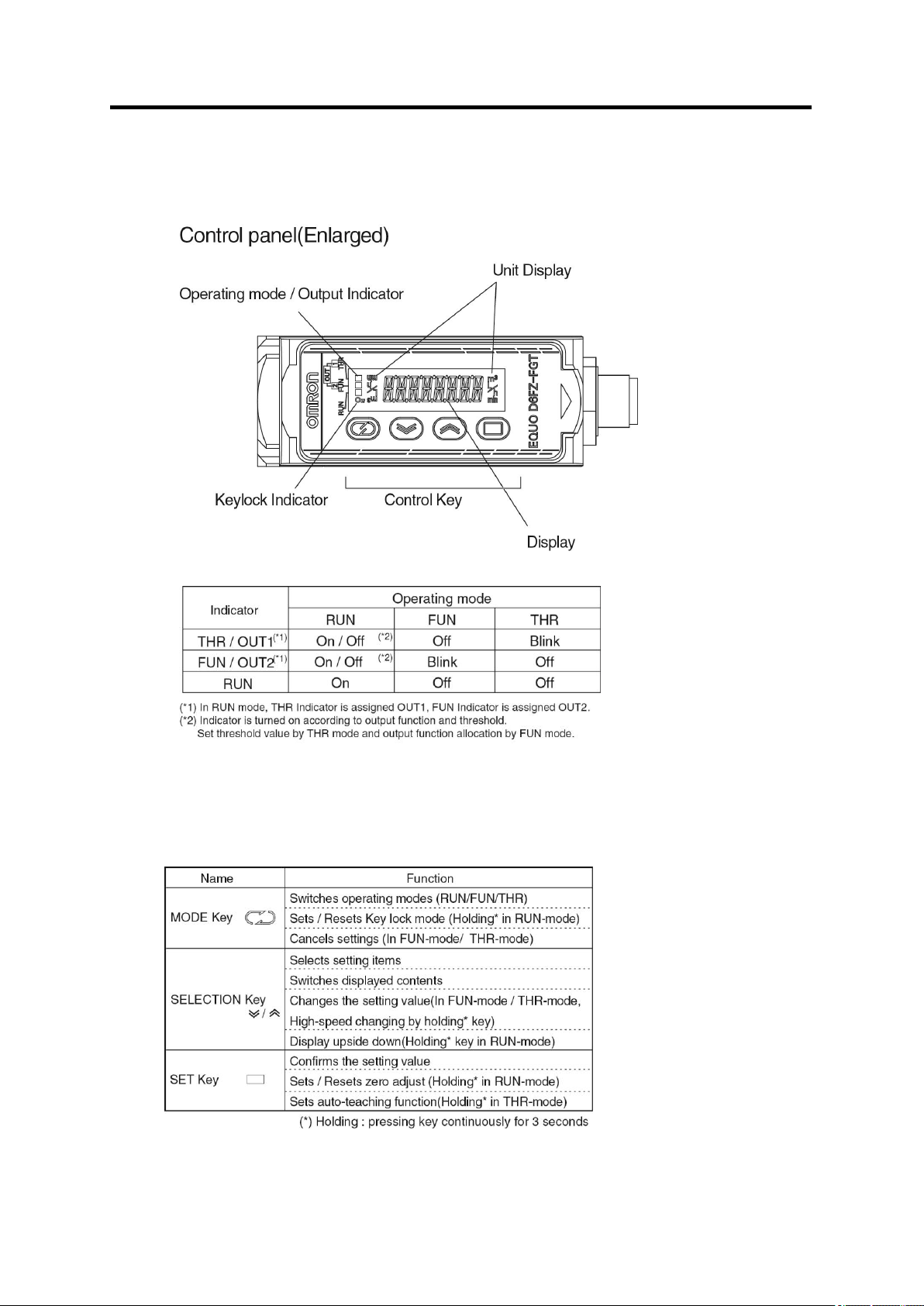
2.2.1 Control Panel / Display
2. Part Name and Function
2.2.2 Control panel
(1) Operation Key
Page 28
2-6
2.2.3 Input/Output Specifications
Analog output
D6FZ-FGT200
D6FZ-FGT500
4mA
0L/min
0L/min
20mA
200L/min
500L/min
Output method
NPN Open collector output
Output stage circuit
diagram
Load power supply voltage
26.4VDC max.
Load current
50mA max. (Residual voltage 2V max.)
Output mode
Pulse output (Pulse width : Approx. 50ms)
Judgment output
Unit error output
Inside D6FZ-FGT
(1) Breakout Cable Wires Color Code (D6FZ-JDA)
The following shows the specifications of the breakout cable connected to the cable
connector socket of an Air Flow Sensor unit.
(2) Linear Output
Output : Current output (4 to 20 mA)
Load resistance: 300 max.
Output content: Momentary flow
2. Part Name and Function
(3) ON/OFF Output
(*)OUT1/OUT2 can be set for any output mode in FUN mode settings.
Page 29
2. Part Name and Function
2-7
SD memory card slot
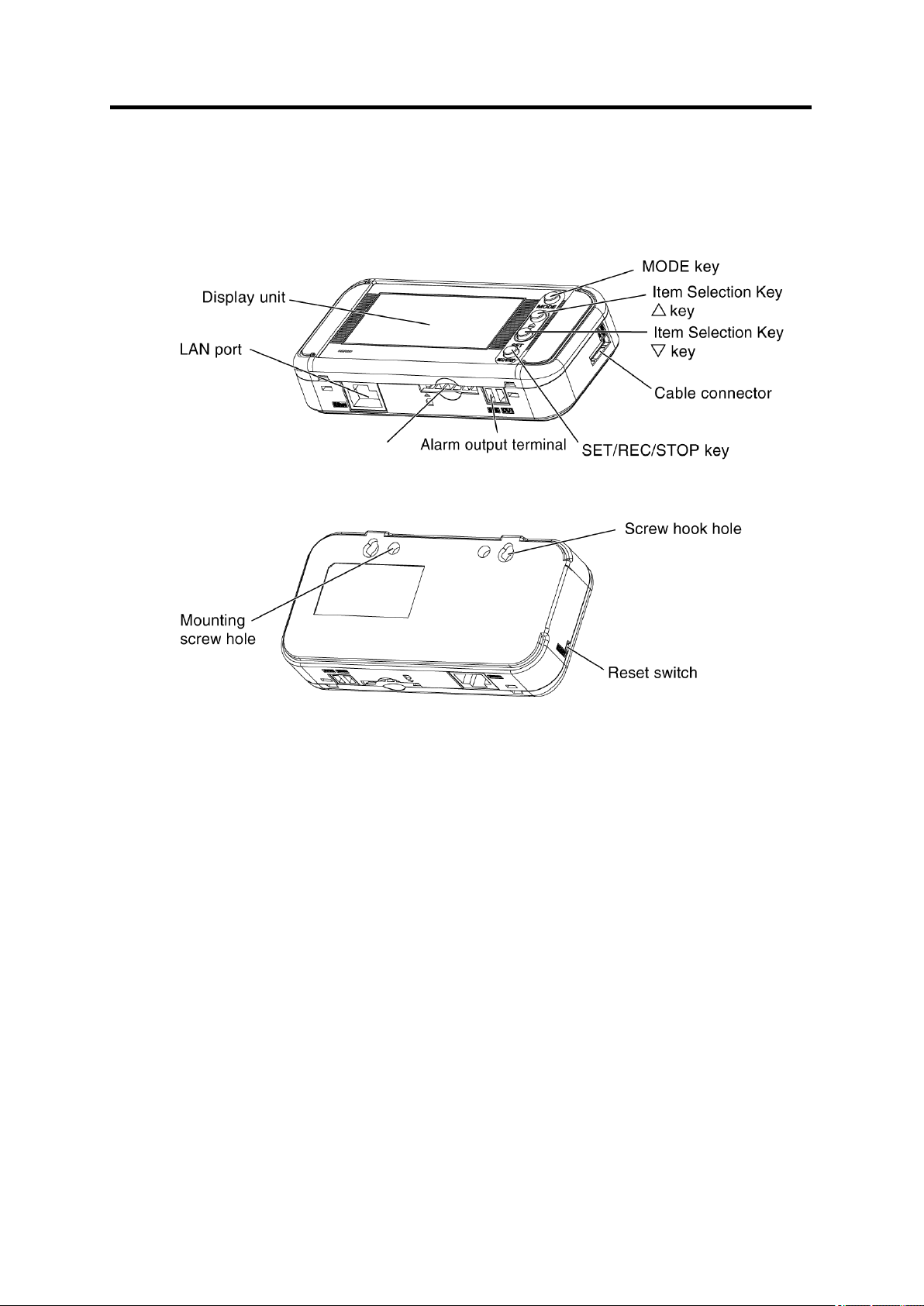
2.3 Air Flow Station (D6FZ-FGX21)
Page 30
2. Part Name and Function
2-8
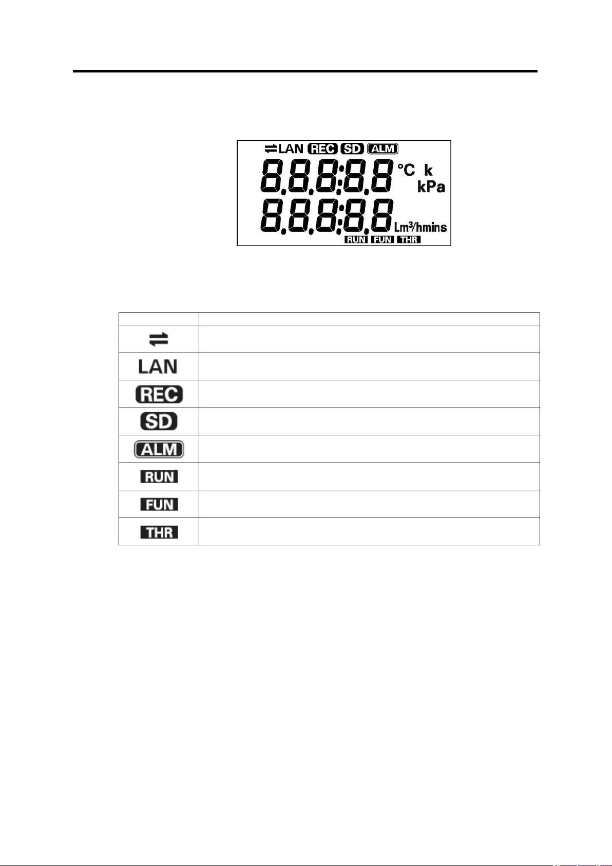
Display
Definition/Function (When Displayed)
Communication via LAN cable is in process.
A LAN cable is connected and network communication is ready.
Data is being recorded in the internal memory.
An SD memory card is inserted.
Blinking: The SD memory card is being accessed.
Any of connected Air Flow Sensors has exceeded the specified upper or
lower threshold.
The unit is currently operating in RUN mode.
The unit is currently operating in FUN mode.
The unit is currently operating in THR mode.
2.3.1 Display Unit
Display Unit
Indicator Definition
“Character Display List" in the last chapter for the definitions of alphabetical, numeric and
principal message displays.
Page 31

2-9
2.3.2 Control Unit
Name
Function
MODE Key
Switches the operation mode.
Resets an alarm or error (Long press).
Cancels the setting before applying it.
Item Selection Key
(△ Key)
Moves the setting items (Upward).
Switches the display.
Changes the setting value (Incremental).
Sequentially switches the Air Flow Sensor IDs
(Long press).
Item Selection Key
(▽ Key)
Moves the setting items (Downward).
Switches the display.
Changes the setting value (Decremental).
SET/REC/STOP Key
Applies the setting value or changes.
Starts/stops recording (Long press).
Saves the recorded data to the SD memory card.
(1) Control Key
(2) Reset Switch
The reset switch is provided inside the aperture on the left side of the Air Flow Station unit.
Used when an SD memory card is not available when recording stops, or when error
recovery cannot be made. Use a thin-tipped object (insulator) such as a pen to press the
switch. The unit resets itself.
Do not touch the front keys when the unit is in reset process, until the air flow rate is
displayed.
Reset operation does not initialize the settings made on the unit.
2. Part Name and Function
(3) Inserting/Removing SD memory card
The Air Flow Station provides an SD memory card slot for SD memory card operation such
as writing the measured data recorded in the internal memory to the card, and
writing/reading the setting data to/from the card.
Important
・Secure the unit firmly when inserting/removing an SD memory card. It is essential
especially when the unit is mounted using the screw hook holes. If the card is inserted /
removed without securing the unit, the unit may be detached from the hooks and drop
on the floor, damaging itself.
・Do not remove the SD memory card when the "SD" on the display unit is blinking. Doing
so may destroy the data in the SD memory card.
・Do not touch the metal terminal of the SD memory card.
・Make sure that the SD memory card does not bend.
・Avoid static electricity when inserting/removing an SD memory card.
・Do not enable the write-protection of the SD memory card.
Page 32

2-10
<Inserting SD memory card>
External Power Supply Voltage
DC12 ~ 24 V ±10%
Load Current
Max. 45 mA
ON Residual Voltage
Max. 1.2 V
OFF Leakage Current
Max. 0.1 mA
Internal Circuit Diagram
Load
External
Power
Supply
<Removing the SD Memory Card>
(1) Push the inserted SD memory card inward until it clicks.
(2) Stop pushing and let the card pops out. Be careful not to drop it.
(3) "SD" on the display disappears.
Important
・If an SD memory card is unformatted, format it before inserting it into the SD card slot.
・For SD memory card format software distribution page, refer to the following URL.
https://www.sdcard.org/downloads/formatter_4/
2.3.3 Input/Output Specifications
2. Part Name and Function
( *)
(1) Insert an SD memory card into the SD memory
card slot with the metal terminal facing up.
(2) Push the card inward until it clicks.
(3) "SD" appears on the display.
(1) Alarm Output
<Alarm Output Terminal>
(1) OUT
Outputs the results allocated in THR mode.
(2) GND
A common terminal.
The terminal names are inscribed on the unit.
Use the provided alarm output connector for wiring.
<Output Specifications>
Important
・Do not connect the external power supply directly between OUT and GND.
・Be sure to connect a load.
Page 33

3-1
3. Check and Preparation
3.1 Checking the Package Contents
This product package includes the following items:
● Air Flow Station (D6FZ-FGX21)
・ Air Flow Station Main Unit 1
・ Connection Cable 1
・ Alarm Output Connector 1
・ Instruction Sheet 1
・ Startup Guide 1
● Air Flow Sensor (D6FZ-FGS1000)
・ Air Flow Sensor Main Unit 1
・ Instruction Sheet 1
3. Check and Preparation
3.2 Preparing the Required Items
The following items are required to use this product.
(1) Common
・ Power Supply: 24VDC (Recommended model: OMRON S8VS-09024BE)
・ T-Branch Connector: D6FZ-FC02
・ Double-Sided Connector Cable: D6FZ-JDB
・ PC (personal computer) for the PC software 1
・ SD Memory Card (SDHC compatible) 1 (Recommended model: HMC-SD291)
(2) Network Connection
・ LAN Cable (10BASE-T or 100BASE-TX; Safety Category 5e or higher; Straight Type)
・ LAN Connection HUB (for 10BASE-T or 100BASE-TX)
Note
Generally, Air Flow Station units should be connected to a PC via a HUB.
Page 34

3-2
3.3 Setting and Installation
Breakout Cable
D6FZ-JDA
Cable Connector Socket
Air Flow Sensor
Breakout Cable
D6FZ-JDA
D6FZ-FGT
3.3.1 Single Air Flow Sensor Unit Operation
(1) Outputting Analog Signals
This section describes the Analog Output/Analog Output/Unit Error Output connection.
(1) Connect the connector of the breakout cable (D6FZ-JDA) to the cable connector
socket of the Air Flow Sensor.
3. Check and Preparation
(2)Connect the following breakout cable wires to the upstream unit as required.
<D6FZ-FGS1000>
Analog Output 1: Black (Pin No. 3)
Analog Output 2: Yellow (Pin No. 4)
Pulse Output: White (Pin No. 1)
Unit Error Output: Red (Pin No. 8)
<D6FZ-FGT>
Analog Output 1: Black (Pin No. 3)
Pulse/Judgment/Unit Error Output: White (Pin No. 1)
Pulse/Judgment/Unit Error Output: Red (Pin No. 8)
Note
Refer to "2.1.3 Input/Output Specifications" for the Analog Output, Pulse Output and
Unit Error Output specifications.
Page 35

3. Check and Preparation
3-3
Breakout Cable
D6FZ-JDA
D6FZ-FGT
(2) Connecting to Power Supply
Connect the breakout cable (D6FZ-JDA) to the power supply.
Connect the blue wire (Pin No. 7) to 0V terminal and the brown wire (Pin No. 2) of the
breakout cable to the DC24 V terminal.
Note
・Refer to the manual of the power supply to connect for the connection procedure.
・The Air Flow Sensor unit does not have a power switch. The unit starts operation
immediately when the power is supplied.
Page 36

3. Check and Preparation
3-4
DIP SW:
Set the communication terminator (No. 1) to OFF on all the four
units.
See the figure below.
Rotary SW:
Assign ID numbers from 01 to 04.
DIP SW:
Set the communication terminator (No. 1) to ON.
Rotary SW:
Assign the ID to "05".
1:OFF
2:OFF
3:OFF
10's Place 1's Place
0 (Fixed)
1:ON
2:OFF
3:OFF
・・・
10's Place 1's Place
0 (Fixed)
Remove Screws
Switch Cover
DIP SW
Rotary SW
3.3.2 Standalone Operation Connecting Air Flow Sensors to Air Flow Station
(1) Air Flow Sensor Setting
Set the Unit No. and Termination resister of the Air Flow Sensor unit. Up to 8 Air Flow
Sensor units can be connected to an Air Flow Station, and it is possible to use
D6FZ-FGS1000 and D6FZ-FGT concurrently.
・ Set Unit No. from 01 in sequence.
・ When more than one sensor is connected with Air Flow Station, communication
terminator of the last sensor must be ON.
< D6FZ-FGS1000 >
This section shows the example of setting five Air Flow Sensor units.
(1) Open the switch cover by removing the screws on the Air Flow Sensor unit.
(2) Make settings on the 1st to 4th units.
(3) Make settings on the 5th unit (termination).
Important
DIP SW and rotary SW settings are applied after the unit is reset.
Page 37

3. Check and Preparation
3-5
< D6FZ-FGT>
By the key operation of the Air Flow Sensor, it is possible to set the Unit No. and Termination
resister.
The Unit No. and Termination resister is set in the FUN mode on D6FZ-FGT.
(1) Setting of the communication setting
In order to set communicati on setting, display the communication setting in
FUN mode.
[1] Press MODE Key and select FUN mode.
[2] Press SELECTION Key (UP - DOWN Key) until "SER" is displayed.
[3] Then Press SET Key, Press SELECTION Key until "DISP" is displayed.
And press SET key again.
(2) Setting of the Unit No.
[1] Select FUN mode by MODE Key.
[2] Press SELECTION Key until "U.No. 01" is displayed. Then Press SET Key.
[3] Press SELECTION Key and set the Unit No. (01 to 08). Then Press SET Key.
(3) Setting of the Termination resister
[1]Select FUN mode by MODE Key
[2] Press SELECTION Key until "TER ON" is displayed. Then Press SET Key.
[3] Press SET Key, and press SELECTION Key until "ON" is displayed.
Then Press SET Key.
Page 38

3. Check and Preparation
3-6
Connection Cable
Air Flow Station
D6FZ-FGX21
Connection Cable
(Length: 1.5 m)
T-Branch
Connector
D6FZ-FC02
Double-Sided
Connector Cable
D6FZ-JD B
Double-Sided
Connector Cable
D6FZ-JD B
Double-Sided
Connector Cable
D6FZ-JD B
T-Branch
Connector
D6FZ-FC02
Max. 8 Air Flow Units can be Connected
Air Flow Sensor
D6FZ-FGT
Air Flow Sensor
D6FZ-FGT
Breakout Cable
D6FZ-JD A
Power Source
(DC24V)
T-Branch
Connector
D6FZ-FC02
Double-Sided
Connector Cable
D6FZ-JD B
Air Flow Sensor
D6FZ-FGS1000
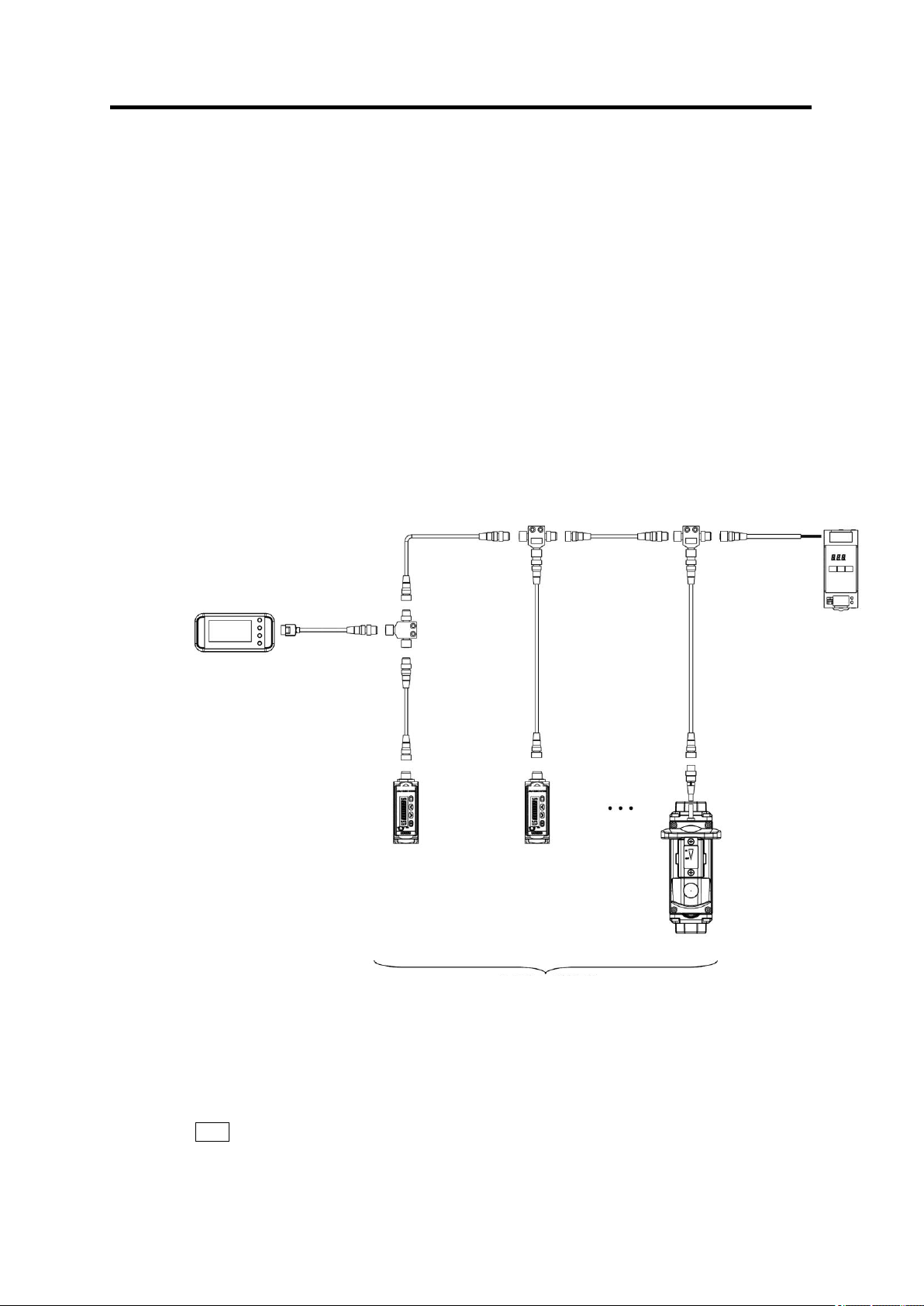
(2) Air Flow Sensor Connection
Up to eight* Air Flow Sensor units can be connected to an Air Flow Station.
Connect the Air Flow Sensor and Air Flow Station units as shown below:
* When the measurement data recording cycle is 2 second or longer. Up to four units when
the cycle is 1 second.
Important
・ The maximum extension cable length between power supply and Air Flow Sensor, between
power supply and Air Flow Station, between Air Flow Sensor and Air Flow Station, is 100 m
respectively.
・ When connecting with Air Flow Station (D6FZ-FGX21), use 24VDC power supply.
・ When the cable length is 30 to 100m between D6FZ-FGS1000 and Air Flow Station,
between D6FZ-FGS1000 and power supply, be sure to ground blue colored wire (0V)
and shield.
(1) Connect the provided connection cable to the Air Flow Station.
Insert the connection cable in the sensor head connector until it clicks.
(2) Connect the connection cable and T-branch connector (D6FZ-FC02).
Page 39
3. Check and Preparation
3-7
Max. 8 Air Flow Units can be Connected
Air Flow Station
D6FZ-FGX21
Connection Cable
(Length: 1.5 m)
T-Branch
Connector
D6FZ-FC02
Double-Sided
Connector Cable
D6FZ-JDB
Double-Sided
Connector Cable
D6FZ-JDB
Double-Sided
Connector Cable
D6FZ-JDB
T-Branch
Connector
D6FZ-FC02
Air Flow Sensor
D6FZ-FGT
Air Flow Sensor
D6FZ-FGT
Breakout Cable
D6FZ-JDA
Power Source
(DC24V)
T-Branch
Connector
D6FZ-FC02
Double-Sided
Connector Cable
D6FZ-JDB
Air Flow Sensor
D6FZ-FGS1000
(3) Connect an Air Flow Sensor unit to a T-branch connectors with the double-sided
connector cable (D6FZ-JDB).
(4) In the same way, connect other Air Flow Sensor units using double-sided connector
cables and T-branch connectors.
(3) Using Alarm Function
Use the provided alarm output connector to connect the OUT and GND alarm output
terminals to the load according to the output specifications. (Refer to "2.3.3 Input/Output
Specifications")
(4) Connecting to Power Supply
Connect the power supply to the T-branch connector to supply power to the Air Flow Sensor
and Air Flow Station units.
(1) Connect the breakout cable (D6FZ-JDA) to the power supply.
Connect the blue wire (Pin No. 7) to 0V and the brown wire (Pin No. 2) of the breakout
cable to DC24V terminals.
Note
(2) Connect the breakout cable connector to the T-branch connector.
Refer to the manual of the power supply to connect for the connection procedure.
Page 40

3. Check and Preparation
3-8
Note
・Air Flow Sensor and Air Flow Station units do not have a power switch. They start
operation immediately when the power is supplied.
・ Be sure to stop the power supply to change the number of the connected Air Flow
Sensor units.
(5) Checking Operation
When the power is supplied, the type name and version are displayed on the display section
for a while. The air flow rate information appears on the display, after the unit checks the
connection with Air Flow Sensor units.
Press ▽ or △ keys to change the display while the "RUN" indicator at the bottom of the
display is ON.
(Refer to "5.3 Screen Transition in RUN Mode")
Important
・Do not touch any front keys until the air flow rate appears on the display after the power
is supplied.
・5 seconds or more waiting time is required until the air flow rate information appears,
since the Air Flow Sensor and Air Flow Station require time to start up.
・The "ALLOK" indication appears when the unit normally recognizes all the connected Air
Flow Sensor units. If the connection is not normally recognized, investigate the cause
by checking wirings, DIP SW setting, ID setting, the number of the connected Air Flow
Station units, or other related issues.
・If a communication failure such as "no response" occurs on multiple Air Flow Sensor
units, after checking the connected unit, the unit with the smallest ID is displayed as
"NGnn" ("nn" stands for the Air Flow Sensor ID).
・The Air Flow Station factory default setting of the number of connected Air Flow Sensor
units is set to "one". To change the number of units, refer to "3.5 Setting the
Measurement Conditions".
・ When operating D6FZ-FGT by the key, select RUN mode on the Air Flow Station.
If the Air Flow Station is in FUN-mode or THR-mode, D6FZ-FGT’s key operations
are not available and D6FZ-FGT’s main display shows “REMOTE”.
・ When setting the Air Flow Station in FUN-mode and THR-mode, be sure that this
product is in RUN-mode. If this product is set in FUN-mode or THR-mode, “REMOTE” is
not displayed and “Error” is displayed on the Air Flow Station.
・ In order to cancel the Error, press the MODE key for more than 3 seconds. And change
settings, set D6FZ-FGT in RUN mode and then set the Air Flow sensor in RUN
mode.
Page 41

3-9
3.4 Overview of PC Software
3.4.1 Overview
This product provides PC software, which consists of the following functions. Refer to the
software's "User's Manual" for details.
・The tool provides Air Flow Station and Air Flow Sensor operations and settings remotely
from the PC connected to the Air Flow Station unit.
・Measured values on Air Flow Stations can be recorded to and displayed to the PC via
network.
・The tool can display the data recorded with the PC software or Air Flow Station units.
・The tool also provides simple data analysis (summation/consolidation/comparison).
3. Check and Preparation
Page 42

3-10
3.5 Setting the Measurement Conditions
Display
(Upper/Lower)
Operation
CYCLE
1s
("FUN" Blinking)
Press the ▽or △ key until "UNIT" appears at the upper row on
the display.
↓▽or △ Key
UNIT
1
The default number of Air Flow Sensor units appears at the lower
row. Press the SET/REC/STOP key.
↓SET/REC/STOP Key
UNIT
1
↑Blinking
The numeral at the lower row starts blinking.
Press the ▽or △ key to set "5".
↓▽or △ Key
UNIT
5
↑Blinking
"5" is applied to UNIT by pressing the SET/REC/STOP key.
↓SET/REC/STOP Key
UNIT
5
The setting is complete when blinking at the lower row stops.
RUN mode
FUN mode
“FUN” blinks
THR mode
MODE key
twice
MODE key
MODE key
Specify the number of Air Flow Sensor units to be connected to the Air Flow Station.
Note
Refer to the sections below for details on messages displayed on the display unit and
operational key functions.
Refer to "2.1.1 Display Unit", "2.1.2 Control Unit", and "4.2
3.5.1 Settings (FUN Mode Operation)
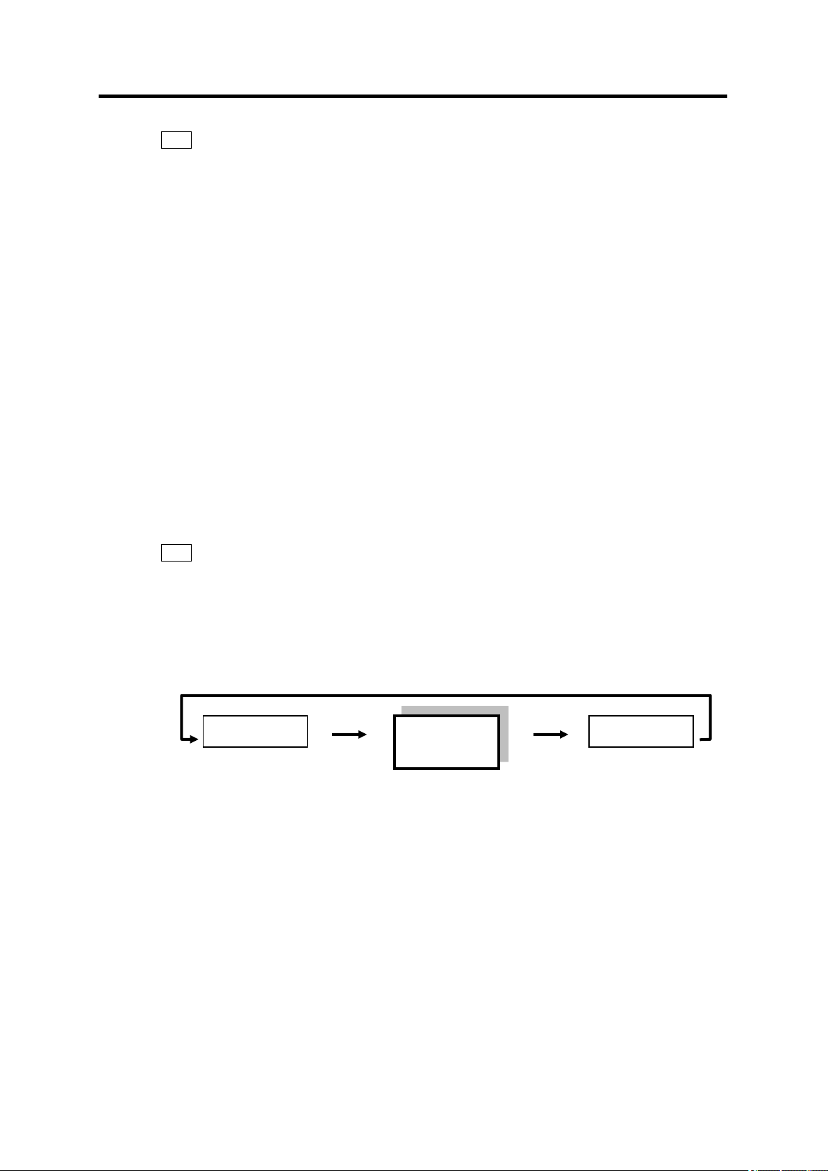
(1) Switching to "FUN" Mode
"FUN" mode should be entered for setting measurement conditions. Press the MODE key
until the "FUN" indicator at the right of the display starts blinking.
3. Check and Preparation
(2) Setting UNIT (the Number) of Air Flow Sensor Units to be Connected
The following shows the operation to set UNIT to "5".
Note
After the value is applied, the unit restarts when the MODE key is pressed twice and FUN
mode is switched to THR mode.
Page 43

3. Check and Preparation
3-11
(3) Data Acquisition Cycle (CYCLE) Setting
・The factory default setting of the data acquisition cycle (CYCLE) is 1 second. Measured
values on four sensor units (eight when the cycle is 2 seconds or longer) can be updated
at this interval.
・Change the data acquisition cycle according to the number of units to connect or the
characteristics of the measurement target.
Page 44

3. Check and Preparation
3-12
Air Flow Station IP Address
(Unit 1) 192.168.0.20 (Factory default)
(Unit 2) 192.168.0.21
PC IP Address
192.168.0.100
Subnet Mask
255.255.255.0 (Factory default)
HUB
W4S1-05C
(Operation check
completed)
PC
IP Address: 192.168.0.100
Subnet Mask: 255.255.255.0
IP Address: 192.168.0.21
Subnet Mask: 255.255.255.0
IP Address: 192.168.0.20
Subnet Mask: 255.255.255.0
LAN Cable
3.6 Connecting to Network
Network settings are required on the Air Flow Station units to be connected to a network.
Connect the LAN cables after completing the network settings on the Air Flow Station units.
Important
・A full understanding of network is required to connect Air Flow Stations to a network.
・Establish a dedicated network for connecting Air Flow Station units to a network.
・Connection to an in-house network or an existing network requires caution, since specific
restrictions or rules may have been applied to the IP address management. Consult
your network administrator. In case that such a network is used, OMRON cannot
guarantee the performance of the Air Flow Station units and the PC software.
3.6.1 Preparation
Define the IP addresses and subnet masks to use before establishing network connection.
Setting Example
Page 45
3-13
Note
RUN mode
FUN mode
“FUN” blinks
THR mode
MODE key
twice
MODE key
MODE key
・Air Flow Station units are assigned by the IP address: 192.168.0.20, and subnet mask:
255.255.255.0 as the factory defaults.
・The IP addresses of Air Flow Station units and the PC must be individually unique and
must not overlap one another in the network. In the example above, Air Flow Station
Unit 2 is assigned with "192.168.0.21", the PC, "192.168.0.100", changing the fourth
value (segment) of the IP address of the Air Flow Station Unit 1, in order to distinguish
among the units connected.
・Set the same subnet mask value to both the Air Flow Station units and PC to be
connected in the network.
・To change the subnet mask, contact your network administrator.
If the subnet mask is changed from 255.255.255.0, the fourth segment of the IP
addresses of the Air Flow Station units and PC in the network still must be distinguished
from one another.
・The setting range of the individual segments of IP address and subnet mask is 0 to 255.
3.6.2 Setting Air Flow Station IP Address
3. Check and Preparation
This section explains the procedure to set the IP address for Air Flow Station Unit 2
(Example: Change the factory default "192.168.0.20" to "192.168.0.21").
Note
Refer to the sections "2.1 Display Unit" and "2.2 Control Unit" for details on messages
displayed on the display unit and operational key functions.
(1) Switching to "FUN" Mode
To change the IP address, press the MODE key until the "FUN" indicator at the right of the
display starts blinking.
Page 46

3-14
(2) Setting ETC and IP to "DISP"
Display
(Upper/Lower)
Operation
CYCLE
1s
("FUN" Blinking)
Press the ▽ or △ key until "ETC" appears at the upper row on
the display.
↓▽or △ Key
ETC
OFF
Press the SET/REC/STOP key. "OFF" at the lower row starts
blinking.
↓SET/REC/STOP Key
ETC
OFF
↑Blinking
Press the ▽ or △ key to display "DISP".
↓▽or △ Key
ETC
DISP
↑Blinking
Press the SET/REC/STOP key to apply "DISP". Blinking stops.
↓SET/REC/STOP Key
ETC
DISP
Press the ▽or △ key to display "IP" at the upper row.
↓▽or △ Key
IP
OFF
Press the SET/REC/STOP key. "OFF" at the lower row starts
blinking.
↓SET/REC/STOP Key
IP
OFF
↑Blinking
Press the ▽ or △ key to display "DISP".
↓▽or △ Key
IP
DISP
↑Blinking
Press the SET/REC/STOP key to apply "DISP". Blinking stops.
↓SET/REC/STOP Key
IP
DISP
Proceed to the IP address setting procedure.
3. Check and Preparation
Page 47

3. Check and Preparation
3-15
Display
(Upper/Lower)
Operation
IP
DISP
Display the first segment of the IP address. Press the ▽ or △
key until "P 1" appears at the upper row.
↓▽or △ Key
IP 1
192
Check that "192" is displayed at the lower row, and press the ▽
key.
If "192" is not displayed, change the value referring to the changing
"IP 4" example shown later.
↓▽ Key
IP 2
168
Check that "168" is displayed at the lower row, and press the ▽
key.
If "168" is not displayed, change the value referring to the changing
"IP 4" example shown later.
↓▽ Key
IP 3
0
Check that "0" is displayed at the lower row, and press the ▽ key.
If "0" is not displayed, change the value referring to the changing
"IP 4" example shown later.
↓▽ Key
IP 4
20
Press the SET/REC/STOP key to change the value displayed at
the lower row to "21".
↓SET/REC/STOP Key
IP 4
020
↑Blinking
The value starts blinking. Press the ▽ or △ key to change the
value to "21".
↓▽or △ Key
IP 4
021
↑Blinking
Press the SET/REC/STOP key to apply the value. Blinking stops.
↓SET/REC/STOP Key
IP 4
21
To check or change the subnet mask, press the ▽ key to display
"SUB1" at the upper row.
↓▽ Key
Check that SUB1 to SUB4 are set to 255, 255, 255 and 0 respectively and apply them
in the same way as the procedure above.
After the settings for IP 1 to IP 4 and SUB1 to SUB4 are completed, press the MODE
key.
"RESET" is displayed and the unit resets itself after the MODE key is pressed again and
THR mode is exited..
(3) Changing IP Address
The following shows the procedure to change the factory default "192.168.0.20" to
"192.168.0.21".
Page 48

3-16
3.6.3 Setting the PC IP Address
This section describes the procedure to change the IP address of the PC to
"192.168.0.100".
Login with a user account with administrator/manager authority, which is required to change
the IP address of the PC.
(1) Windows XP
Follow the procedure below to set the IP address.
(1) Select "Start menu" – "Setup" – "Control Panel" to display the Control Panel and click
"Network and Internet Connections".
3. Check and Preparation
Page 49

3-17
(2) Click "Network Connections".
3. Check and Preparation
(3) Right-click "Local Area Connection" and select "Properties".
Page 50

3-18
(4) Highlight "Internet Protocol (TCP/IP)" and click "Properties".
3. Check and Preparation
(5) Select "Use the following IP address" and set "IP address" to "192.168.0.100" and
"Subnet mask" to "255.255.255.0". Press "OK" to close the window.
(6) Click "OK" in the "Local Area Connection Properties" window. The window
closes.
Page 51

3. Check and Preparation
3-19
(2) Windows Vista
Follow the procedure below to set the IP address.
(1) Select "Start menu" – "Control Panel" and click "Network and Internet".
(2) Click "Network and Sharing Center".
Page 52

3-20
(3) Click "Manage network connections".
3. Check and Preparation
(4) Right-click "Local Area Connection" and select "Properties".
(5) When the "User Account Control" window appears, click "Continue".
Page 53

3. Check and Preparation
3-21
(6) Select "Internet Protocol Version 4 (TCP/IPv4)" and click "Properties".
(7) Select "Use the following IP address" and set "IP address" and "Subnet mask". Click
"OK" to close the window.
(8) Click "Close" in the "Local Area Connections Properties" window. The window closes.
Page 54

3. Check and Preparation
3-22
(3) Windows 7
Follow the procedure below to set the IP address.
(1) Select "Start menu" – "Control Panel" and click "Network and Internet".
(2) Click "Network and Sharing Center".
Page 55

3-23
(3) Click "Change adapter settings".
3. Check and Preparation
(4) Right-click "Local Area Connection" and select "Properties".
Page 56

3. Check and Preparation
3-24
(5) Select "Internet Protocol Version 4 (TCP/IPv4)" and click "Properties".
(6) Select "Use the following IP address" and set "IP address" and "Subnet mask". Click
"OK" to close the window.
(7) Click "Close" in the “Local Area Connections Properties” window. The window closes.
Page 57

3-25
3.6.4 Connecting a LAN Cable
Click!
Use a LAN cable to connect an Air Flow Station unit to the PC. The "LAN" symbol appears
on the display when the unit is connected to the network.
3. Check and Preparation
Page 58

3. Check and Preparation
3-26
<Direct Mounting on Pipe>
<Quick Coupling Mounting>
Flow Direction
Flow Direction
3.7 Mounting Air Flow Sensor and Air Flow Station
This section explains the procedure to mount Air Flow Sensor units to an Air Flow Station.
Important
This product is precision equipment. Be careful not to drop the unit.
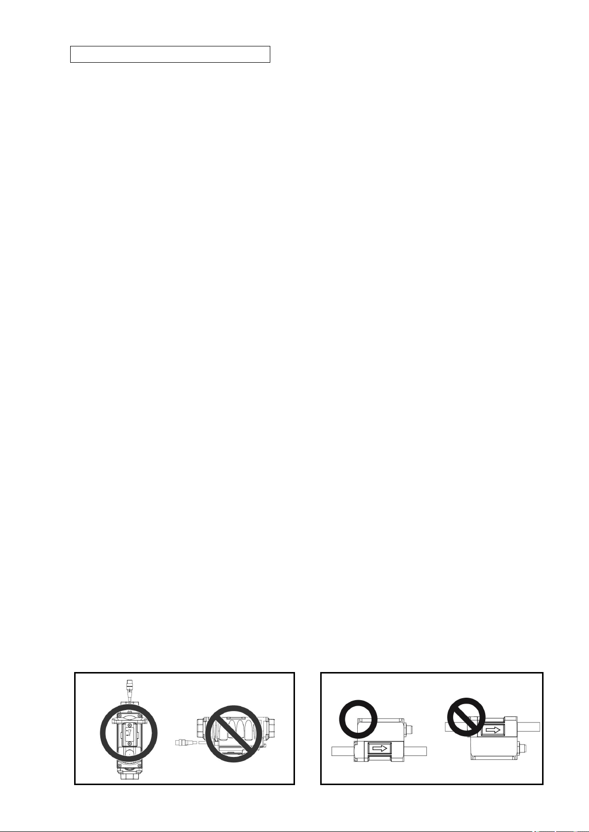
3.7.1 Mounting Air Flow Sensor
(1) Mounting Air Flow Sensor to Supply Pipe
D6FZ-FGS1000
The following shows the supply pipe specifications for mounting an Air Flow Sensor.
Applicable Pipe Diameter: 25 A (Can be converted to 15 A、20 A with a bushing)
Applicable Pipe: SUS Sch10S, SGP
Directly mount on the pipe.
Note the following points to mount an Air Flow Sensor unit.
・Firmly tighten the screws at a torque from 36 to 38 N・m.
・Do not apply pressure to the main unit (except the screws) and the cable connector
socket area.
・Make sure that foreign matter does not enter the unit when piping.
・Check the flow direction when mounting the unit.
Mounting on a vertical pipe is recommended to minimize the deposit of mist or dust
inside the pipe.
When mounting on a horizontal pipe, make sure that the status indicator does not face
down. If this happens, mist or dust may deposit inside the pipe, causing malfunction.
・
Page 59

3. Check and Preparation
3-27
Model
Tightening torque
D6FZ-FGT200
12 to 14N.m
D6FZ-FGT500
31 to 33N.m
Flow Direction
D6FZ-FGT
The following shows the supply pipe specifications.
Applicable diameter: D6FZ-FGT200 / 8A(Rc1/4) D6FZ-FGT500 / 15A(Rc1/2)
Precautions for piping
When piping, fix with the part of conduit by wrench.
And secure piping with the tightening torque of the following list.
・ Fix with only the conduit part when piping. Do not fix with other parts, or the product
might be damaged.
・ When fixing with the part of flow channel by wrench, cover the body with something
like a waste cloth. If holding the body with a wrench directly, the body might be
damaged.
・ Check the flow direction before mounting pipes.
・ Do not apply force on other than conduit.
・ Make sure that foreign objects do not enter inside the body when piping.
・ Be sure to mount the body horizontally, otherwise the detection accuracy might be
worse.
・ Don't mount the body facing the control panel downward. Otherwise, the mist and
dust in the pipe accumulates and it might cause breakdown.
Page 60

3. Check and Preparation
3-28
M3 Screws: x 6
3.7.2 Mounting Air Flow Station Unit
Important
Use screws to fix the product through the provided mounting screw holes for installation
on the wall or other equipment where vibration or shock may directly affect the unit.
(1) Free-stand Installation
Important
When placing the product on a desk or other similar location, place it at a sufficient
distance from the edges or corners of the object to prevent the unit from dropping to be
damaged. Take caution in handling the connection cable and LAN cable to avoid their
contacting the unit.
(2) Securing with Mounting Screws
Mounting screw holes are provided on the rear side of the unit, which enables fixing the unit
on the wall or other vertical surface.
The holes also can hold round mounting magnets to magnetically secure the unit.
(Refer to the Appendix: Installation Diagram for the screw hole dimensions.)
Important
The screw holes are 4 mm deep. Do not screw deeper than 4 mm, which may damage
the product.
Page 61

3. Check and Preparation
3-29
Flat-head Screws: M3 x 6
Mounting Magnets
2.5 mm or more
Enlarged Hook Screw Section View
Note
・The unit can be magnetically secured by ZN9-WM01-S magnets (sold separately) placed
in the screw holes. (Tightening torque: 0.4 N/cm to 0.6 N/cm)
・Mount the unit on a location where mechanical shock is not applied when mounting it
with magnets.
・Be careful not to allow the sensor head and cable to apply pressure to the
magnet-mounted unit.
(3) Mounting with Screw Hook Holes
Two screw hook holes are provided below the convex section of the upper unit area, which
allows fixing the unit on the wall or other vertical surface. (Refer to the Appendix: Installation
Diagram for the screw hooking hole dimensions.)
Fix M3 screws on the wall and hook the unit on the screw heads through the holes. Allow a
distance of 2.5 mm or more between the bottom of the screw heads and the wall surface.
Important
Firmly hold the unit with a hand to insert or remove the SD memory card if the unit is
mounted by hooking. Otherwise the unit may drop on the floor and be damaged.
Page 62

3. Check and Preparation
3-30
3.8 Remotely Setting Air Flow Sensors and Air Flow Station
Remote settings of Air Flow Sensor and Air Flow Station units from the PC via network are
possible using the PC software.
Refer to the "User's Manual" of the PC software for the details of setting procedures.
Page 63

4. Setting (Air Flow Station Operation)
4-1
Display
Name
Description
"RUN" ON
Measurement
Execution Mode
(RUN Mode)
Used for air flow measurement and recording.
"FUN"
Blinking
Function Setting Mode
(FUN Mode)
Entered to make measurement and recording
settings.
"THR"
Blinking
Threshold Setting
Mode
(THR Mode)
Sets the threshold of the status indicator of Air
Flow Sensor and the upper / lower limit
thresholds of Air Flow Sensor for alarm outputs.
RUN Mode
FUN Mode
THR Mode
MODE Key
Twice
MODE Key
MODE Key
△/▽ Key
△/▽ Key
△/▽ Key
RUN Mode
Operation
FUN Mode
Operation
THR Mode
Operation
4. Setting (Air Flow Station Operation)
Air Flow Sensor’s settings can be changed by Air Flow Station.
But relating to the advanced settings of Air Flow Sensor D6FZ-FGT, change a detailed setup by
the key operation of a sensor.
Regarding to the operation, refer to the Instruction Sheet contained in the package.
4.1 Setting Procedure and Operation Modes
The following diagram shows the Air Flow Station setting procedure flow:
The Air Flow Station provides the three operation modes, which can be switched with the
MODE key.
To change the mode from RUN to FUN, press the MODE key twice. When pressing the
MODE key once, "RUN" blinks. When pressing it twice, "FUN" blinks and the mode is
switched.
Use the △ and ▽ keys to change and display items in each operation mode.
Note
・The mode cannot be changed during data recording in the internal memory in RUN
mode ("REC" is displayed).
・During the transition from THR mode to RUN mode, the Air Flow Sensor process standby
indication appears on the display.
Page 64

4-2
4.2 Settings (FUN Mode Operation)
FUN mode provides the following settings:
・Air Flow Station measurement and recording settings
・Settings for Air Flow Sensor units (Pulse setting, Flow rate full-scale value*, Frequency
of averaging, Measurement target gas*)
Note
The setting parameters for Air Flow Sensor units are retained in individual sensor units,
and not in Air Flow Station units.
* Settings of the flow rate full-scale value and Measurement target gas are available for
only D6FZ-FGS1000.
4. Setting (Air Flow Station Operation)
Page 65

4. Setting (Air Flow Station Operation)
4-3
Display Item
Display
Setting Item
Setting Value
Factory
Default
CYCLE
Data recording
interval
1s (sec.)/2s/5s/10s/20s/
30s/1m (min.)
1s
UNIT
Number of
sensor units
connected
1 to 8
1
INIT
Initialize Air
Flow Station
settings
Initialization starts at a long
press of the
SET/REC/STOP key. The
unit restarts when the
MODE key is pressed twice
and THR mode is exited
after the "DONE" indication
appears.
-
(*1)
NN.SET
(DISP)
NN.PLS (*1)
Pulse setting
1.0/10.0/100.0/1000.0
(L/Pulse) (*2)
1.0
NN.SCL (*1)
Flow rate
full-scale value
0 to 1000
1000
NN.AVE (*1)
Frequency of
averaging
1/2/4/8/16/32 (times)
16 (*4)
NN.GAS (*1)
Measurement
target gas
Air / N2
Air
ETC
(DISP)
RESTR
Read setting
data from the
SD memory
card.
The unit reads setting data
from a pre-inserted SD
memory card at a long
press of the
SET/REC/STOP key and
uses the data to set itself.
The unit restarts when the
MODE key is pressed twice
and THR mode is exited
after the "DONE" indication
appears.
-
BCKUP
Write setting
data to the SD
memory card.
The unit saves the setting
data in a pre-inserted SD
memory card, at a long
press of the
SET/REC/STOP key.
-
CLOCK
(DISP)
YEAR
Year
Year setting
Not
initialized
by INIT.
MONTH
Month
Month setting
DAY
Day
Day setting
TIME
Hour/Minute
Hour/minute setting
4.2.1 List of Setting Items
The following list shows the setting items available in FUN mode.
Page 66

4. Setting (Air Flow Station Operation)
4-4
IP
(DISP)
IP1 to
IP4
IP address
0 to 255
192.
168.
0.
20
SUB1 to
SUB4
Subnet
mask
0 to 255
255.
255.
255.
0
RATE
Rate/CO2
conversion
value
setting
0.000 to 99.999
0
CONV
Conversion
unit
JPY/USD/EUR/CNY/
KRW/CO2
JPY
FUNIT
Unit of
display
L/min m3/min L/h m3/h
L/min
REREC
Auto backup
and restarting
record setting
ON/OFF
OFF
RUN Mode
FUN Mode
THR Mode
MODE Key
Twice
MODE Key
MODE Key
△/▽ Key
△/▽ Key
△/▽ Key
RUN Mode
Operation
FUN Mode
Operation
THR Mode
Operation
*1: NN: Unit No. of the Air Flow Sensor which is designated by in RUN mode.
*2: These values are for D6FZ-FGS1000.D6FZ-FGT, setting values are
0.0/100.0/1000.0 (L/Pulse) . 1.0L/Pulse cannot be set.
*3: These values are for D6FZ-FGS1000. D6FZ-FGT, “----“ is displayed (no selecting
Item)
*4: This value is for D6FZ-FGS1000. For D6FZ-FGT, default value is “8”.
4.2.2 Selecting "FUN" Operation Mode
Press the MODE key to change the operation mode to "FUN". "FUN" at the lower right of the
display starts blinking.
Note
FUN mode cannot be entered when recording in the internal memory is in progress in
RUN mode ("REC" indicator is lighted on the display).
Page 67

4-5
4.2.3 Selecting Items
Move the selection items using the △ and ▽ keys. To change the set value, select the
item with △ or ▽ key and fix it with the SET/REC/STOP key. Press the MODE key to
change the operation mode.
4. Setting (Air Flow Station Operation)
Page 68

4. Setting (Air Flow Station Operation)
4-6
Initializes setting values
Not Initializes setting values
・Data collection cycle
・Number of connected Air Flow Sensors
・IP address
・Rate conversion, CO2 conversion and the
conversion unit.
・Auto backup and restarting record setting
・Alarm hold setting
・Year, Month, Day, Hour, Minute, Second
・Sensor setting values
(Pulse setting, Flow full-scale value,
Averaging count, Measurement target gas)
・Sensor threshold value (Hi, Lo, Cut)
4.2.4 Description of Items
(1) Data Recording Interval (CYCLE)
Specifies the interval of measured value recording.
The range of selection (Options):
1s (second)/ 2s / 5s / 10s / 20s / 30s / 1m (minute)
Initial value: 1s
(2) Number of Air Flow Sensor Units Connected (UNIT)
Specifies the number of Air Flow Sensor units to be connected.
The range of selection (Numeric input):
1 to 8
Initial value: 1
(3) Initialization (INIT)
The unit initializes the setting values and restores the factory defaults (except for year,
month, day, hour and minute settings).
Important
The unit initializes setting values about Air Flow Station itself, not initializes the values about
Air Flow Sensors. Please refer to the following table.
Operation:
Holding the SET/REC/STOP key starts initialization and it is finished when “DONE” is
displayed. Before showed “DONE”, the initialization is canceled.
After initialization, press the MODE key twice to exit THR mode. The unit is restarted
and the setting values are initialized.
Page 69

4. Setting (Air Flow Station Operation)
4-7
Setting Value
Operation
OFF
The unit does not display the items including Pulse setting, Flow
rate full-scale value, Frequency of averaging, and Measurement
target gas.
The ETC item returns when the ▽ key is pressed after the setting is
applied with the SET/REC/STOP key.
DISP
The unit displays the items including Pulse setting, Flow rate
full-scale value, Frequency of averaging, and Measurement target
gas.
The NN.SET item is displayed when the ▽ key is pressed after the
setting is applied with the SET/REC/STOP key.
(4) Setting for Air Flow Sensor (NN.SET)
Specifies whether the items including Air Flow Sensor pulse setting, Flow rate full-scale
value, Frequency of averaging, and Measurement target gas are displayed or not. The
setting is made for the Air Flow Sensor unit whose ID is selected in RUN mode.
NN : Unit No. of the Air Flow Sensor which is designated by in RUN mode.
The range of selection (Options):
OFF / DISP
Initial value:
OFF
Note
The NN.SET setting returns to "OFF" when the unit is reset.
(5) Pulse Setting
Specifies the integrated flow rate for a single pulse output from the Air Flow Sensor unit. The
pulse toggles ON/OFF when the sensor detects the half of a specified flow rate.
D6FZ-FGS1000
The range of selection (Options):
1.0/10.0/100.0/1000.0 (L/Pulse)
Initial value:
10.0
D6FZ-FGT
The range of selection (Options):
10.0/100.0/1000.0 (L/Pulse)
Initial value:
10.0 (D6FZ-FGT200/500)
Note
The Pulse setting is not available when NN.SET is set to OFF.
The momentary flow units of the Air Flow Station are m3/min or m3/h, the unit of pulse is
m3/Pulse.
(E.g. 1.0 L/Pulse → 0.001 m3/Pulse , 1000.0 L/Pulse → 1.0 m3/Pulse )
(6) Flow Rate Full-Scale Value
Specifies the flow rate full-scale value for Analog Output 1 from the Air Flow Sensor unit.
Page 70

4. Setting (Air Flow Station Operation)
4-8
Setting Value
Description
AIR
Air
N2
Nitrogen
D6FZ-FGS1000
The range of selection (Numeric input):
0 to 1000
Initial value:
1000
D6FZ-FGT
The range of selection (Options):
----Initial value:
(none)
Note
The Flow rate full-scale value setting is not available when NN.SET is set to OFF.
(7) Frequency of Averaging
Specified the frequency of averaging when obtaining the measured value.
The range of selection (Options):
1/2/4/8/16/32 (times)
Initial value:
16
Note
The Frequency of averaging setting is not available when NN.SET is set to OFF.
* For D6FZ-FGT, default value is “8”.
(8) Measurement Target Gas
Specifies the gas to be measured by the Air Flow Sensor unit.
D6FZ-FGS1000
The range of selection (Options):
AIR / N2
Initial value:
AIR
D6FZ-FGT
The range of selection (Options):
----Initial value:
(none)
Note
The Measurement target gas setting is not available when NN.SET is set to OFF.
(9) Others (ETC)
Specifies if the unit displays the items for setting file read/write, time setting, IP address,
rate/CO2 conversion value setting and conversion unit setting.
Page 71

4. Setting (Air Flow Station Operation)
4-9
Setting Value
Operation
OFF
The unit does not display the items for setting file read/write, time
setting, IP address, rate/CO2 conversion value setting and
conversion unit setting.
The CYCLE item returns when the ▽ key is pressed after the
setting is applied with the SET/REC/STOP key.
DISP
The unit displays the items for setting file read/write, time setting, IP
address, rate/CO2 conversion value setting and conversion unit
setting.
The RESTR item is displayed when the ▽ key is pressed after the
setting is applied with the SET/REC/STOP key.
The range of selection (Options):
OFF / DISP
Initial value: OFF
Note
The ETC setting returns to "OFF" when the unit is reset.
(10) Reading Setting Data (RESTR)
Restores the Air Flow Station unit settings by using the SD memory card with the setting
data saved as a backup using the BCKUP setting (described later).
Operation:
Insert the SD memory card containing the setting data, and hold the SET/REC/STOP
key. Reading is completed when “DONE” is displayed.
The process standby display appears and initialization starts after the process is
complete. If the key is released before the process is complete, initialization is
cancelled.
The unit resets itself when the MODE key is pressed twice and THR mode is exited
after initialization is complete.
Note
・Only one setting data item (the setting data for only one Air Flow Station unit) can be
stored in a single SD memory card as a backup.
・Setting data reading is not possible when ETC is set to "OFF".
・Air Flow Sensor settings are not backed up.
Page 72

4. Setting (Air Flow Station Operation)
4-10
Setting Value
Operation
OFF
Time setting is not available.
The IP item is displayed when the ▽ key is pressed after the setting
is applied with the SET/REC/STOP key.
DISP
Time setting is available.
The YEAR item is displayed when the ▽ key is pressed after the
setting is applied with the SET/REC/STOP key.
(11) Writing the Setting Data (BCKUP)
Saves the Air Flow Station unit setting data in an SD memory card as a backup.
Operation:
Insert an SD memory card and hold the SET/REC/STOP key.
Saving is complete when "DONE" is displayed.
The process standby display appears and initialization starts after the process is
complete. If the key is released before the process is complete, initialization is
cancelled.
Important
Only one setting data item (the setting data for only one unit) can be stored in a single SD
memory card as a backup. If an SD memory card containing an already-saved setting
data backup is used, the setting data in the card is overwritten. The same applies to a
backup performed on other Air Flow Station units: the data is overwritten.
Note
・The setting data is written into the SYSTEM folder in the SD memory card.
・Setting data writing is not possible when ETC is set to "OFF".
・Air Flow Sensor settings are not backed up.
(12) Setting Clock (CLOCK)
Specifies if the internal clock setting is required.
The range of selection (Options):
OFF / DISP
Initial value: OFF
Note
・The CLOCK setting is not possible when ETC is set to "OFF".
・The CLOCK setting returns to "OFF" when the unit is reset.
Page 73

4. Setting (Air Flow Station Operation)
4-11
Setting Value
Operation
OFF
IP address setting is not available.
The SDISP item is displayed when the ▽ key is pressed after the
setting is applied with the SET/REC/STOP key.
DISP
IP address setting is available.
The IP 1 item is displayed when the ▽ key is pressed after the
setting is applied with the SET/REC/STOP key.
(13) YEAR/MONTH/DAY/TIME Setting
Specifies the year/month/day/time values.
The range of selection (Numeric input):
YEAR: 2000 to 2099
MONTH:1 to 12
DAY: 1 to 31
TIME: 00:00 to 23:59
Note
The year/month/day/time settings are not possible when ETC is set to "OFF" and CLOCK
is also set to "OFF".
(14) Setting IP Address (IP)
Specifies if the IP address setting is required.
The range of selection (Options):
OFF / DISP
Initial value: OFF
Note
・The IP setting is not possible when ETC is set to "OFF".
・The IP setting returns to "OFF" when the unit is reset.
Page 74

4. Setting (Air Flow Station Operation)
4-12
(15) IP Address and Subnet Mask (IP 1 to IP 4, SUB 1 to SUB 4)
Specifies the 4 segments of the IP address (IP 1 to IP 4) and the 4 segments of the subnet
mask (SUB 1 to SUB 4).
The range of selection (Numeric input):
IP 1, IP 2, IP 3, IP 4: 0 to 255
SUB 1, SUB 2, SUB 3, SUB 4: 0 to 255
Initial value: IP 1.IP 2.IP 3.IP 4 = 192.168.0.20
SUB 1.SUB 2.SUB 3.SUB 4 = 255.255.255.0
Note
・The unit resets itself when the MODE key is pressed twice and THR mode is exited, after
the IP address and subnet mask values have been changed and applied with the
SET/REC/STOP key.
・The IP address and subnet mask settings are not possible when ETC is set to "OFF" and
IP is also set to "OFF".
(16) Rate/CO2 Conversion Value Setting (RATE)
Specifies the rate or CO2 emission level per 1 m3 of integrated flow rate.
The range of selection (Numeric input):
0.000 to 99.999 (times)
Initial value: 0
Note
The rate/CO2 conversion value setting is not possible when ETC is set to "OFF".
(17) Conversion Unit Setting (CONV)
Specifies the unit for the rate/CO2 conversion setting (RATE).
The range of selection (Options):
JPY (Japanese yen) / USD (US dollar) / EUR (Euro) / CNY (Chinese yuan) / KRW
(Korean won) / CO2 (CO2 emission level per 1m3)
Initial value: JPY
Note
The conversion unit setting is not possible when ETC is set to "OFF".
Page 75

4. Setting (Air Flow Station Operation)
4-13
(18) Unit of Display Setting (FUNIT)
Specifies the unit for displaying the momentary standard flow rate.
The range of selection (Options):
L/min, m3/min, L/h m3/h
Initial value: L/min
Note
The unit of display cannot be specified when ETC is set to "OFF".
(19) Auto backup and restarting record setting(REREC)
When this function is ON, if power shutdown happens during the record, the recorded
measurement data before the interruption of power is backed up to SD memory card and
record is resumed after power is back.
While this function is ON, insert the recordable SD memory card into the SD memory card
slot.
After restarting record, integrated flow value is not cleared.
Page 76

4. Setting (Air Flow Station Operation)
4-14
Display
(Upper/Lower)
Operation
CYCLE
1s
Press the MODE key repeatedly until "FUN" starts blinking.
Press the ▽ or △ key to display CYCLE at the upper row of the
display.
Press the SET/REC/STOP key, then, the value at the lower row
starts blinking.
↓SET/REC/STOP Key
Display
(Upper/Lower)
Operation
CYCLE
1s
↑Blinking
The value options are displayed in sequence by pressing the △ or
▽ key.
To cancel the setting attempt, press the MODE key.
↓▽or △ Key
Display
(Upper/Lower)
Operation
CYCLE
30s
↑Blinking
Press the △ or ▽ key to display the desired value, and press the
SET/REC/STOP key.
↓SET/REC/STOP Key
Display
(Upper/Lower)
Operation
CYCLE
30s
The setting is complete when the value stops blinking.
4.2.5 Changing Air Flow Station Set Value
This section explains the procedure to change Air Flow Station set values.
The value setting depends on the type of items, which are classified into option selection
type and numeric input type.
(1) Changing Option Type Item Value (Example: CYCLE)
Press the MODE key several times to enter FUN mode, and press the ▽ or △ key to
display CYCLE.
Use the △ or ▽ key again to display another setting item and MODE key to change the
operation mode.
Page 77

4. Setting (Air Flow Station Operation)
4-15
Display
(Upper/Lower)
Operation
CYCLE
1s
("FUN" Blinking)
Press the MODE key repeatedly until "FUN" starts blinking.
"CYCLE" is displayed at the upper row.
Press the ▽ or △ key to display YEAR. To display YEAR, ETC
and CLOCK must be set to DISP.
↓▽or △ Key
Display
(Upper/Lower)
Operation
YEAR
2010
Press the SET/REC/STOP key, then, the last digit number at the
lower row starts blinking.
↓SET/REC/STOP Key
Display
(Upper/Lower)
Operation
YEAR
2010
↑Blinking
The value increases or decreases at a press of the △ or ▽ key.
The amount of increase/decrease becomes larger by holding △ or
▽ key.
To cancel the setting attempt, press the MODE key.
↓▽or △ Key
Display
(Upper/Lower)
Operation
YEAR
2011
↑Blinking
Press the △ or ▽ key to display the desired value, and press the
SET/REC/STOP key.
↓SET/REC/STOP Key
Display
(Upper/Lower)
Operation
YEAR
2011
The setting is complete when the value stops blinking.
(2) Changing Numeric Input Type Item Value (Example: YEAR)
Press the MODE key several times to enter FUN mode, and press the ▽ or △ key to
display YEAR.
To display YEAR, ETC and CLOCK must have been set to DISP beforehand.
Use the △ or ▽ key again to display another setting item and MODE key to change the
operation mode.
Page 78

4. Setting (Air Flow Station Operation)
4-16
Display
(Upper/Lower)
Operation
01.F01
Integrated Standard
Flow Rate
("RUN" Blinking)
Press the MODE key repeatedly until "RUN" starts blinking.
The Air Flow Sensor unit ID and measured value code is displayed
at the upper row.
The measured value is displayed at the lower row. The integrated
standard flow rate is displayed here.
A long press of the △ key switches Air Flow Sensor unit IDs. Hold
the key until the ID of the target unit appears.
↓Hold △ Key
Display
(Upper/Lower)
Operation
03.F01
Integrated Standard
Flow Rate
For example, display "03" as the ID.
Display
(Upper/Lower)
Operation
CYCLE
1s
("FUN" Blinking)
Press the MODE key repeatedly until "FUN" starts blinking.
(The status indicator of the ID03 Air Flow Sensor blinks in yellow
when the unit enters FUN mode.)
"CYCLE" is displayed at the upper row.
Press the ▽ or △ key to display NN.SET.
↓▽or △ Key
Display
(Upper/Lower)
Operation
NN.SET
OFF
Press the SET/REC/STOP key. The set value at the lower row
starts blinking.
↓SET/REC/STOP Key
Display
(Upper/Lower)
Operation
NN.SET
OFF
↑Blinking
Press the ▽ or △ key to display DISP, and then, press the
SET/REC/STOP key.
↓SET/REC/STOP Key
Display
(Upper/Lower)
Operation
NN.SET
DISP
↑Blinking
The setting is applied when DISP stops blinking.
4.2.6 Changing Air Flow Sensor Set Value
This section explains the procedure to change Air Flow Sensor set values.
Follow the steps below.
(1) Display the ID of the target Air Flow Sensor unit in RUN mode.
(Refer to "5.3 Screen Transition in RUN Mode" for details of the operation procedure.)
(2) Switch the mode to FUN mode and set NN.SET to "DISP".
Page 79

4. Setting (Air Flow Station Operation)
4-17
(3) Change the setting item value for the Air Flow Sensor unit.
The values for the Pulse setting (NN.PLS), Flow rate full-scale (NN.SCL), Frequency of
averaging (NN.AVE) and Measurement target gas (NN.GAS) items can be changed in the
same way.
(Refer to "4.2.5 Changing Air Flow Station Set Value" for the operation procedure.)
* Flow full-scale value and measurement target gas can be set by only D6FZ-FGS1000.
On D6FZ-FGT, the “-----” is displayed and the setting is not available.
(4) To change set values for Air Flow Sensor unit, display the target sensor’s ID in RUN
mode and repeat steps 1 to 3.
During changing setting values by Air Flow Station, the indicator of the D6FZ-FGS1000 is
blinking with yellow light, and D6FZ-FGT displays “REMOTE” and key operations are
not available.
When mode of the Air Flow Station is returned to RUN-mode, the sensors will return to
normal operation.
Page 80

4-18
4.3 Settings (THR Mode Operation)
Model
D6FZ-FGS1000
D6FZ-FGT500
D6FZ-FGT200
Hi (Upper threshold)
1000 L/min
250 L/min
100 L/min
Lo (Lower threshold)
0 L/min
250 L/min
100 L/min
Cut
(Leak Detection Flow Rate)
0 L/min
0 L/min
0 L/min
Air Flow Sensor Unit Status
Indicator
Definition
(1)
Orange Blink
The air flow rate exceeds the upper threshold value.
(2)
Green ON
The air flow rate is normal and between the upper
and lower threshold values.
(3)
Orange Slow Blink *1
The air flow rate exceeds the lower threshold value.
(4)
Green Slow Blink *2
The air flow rate is zero.
The rate is within the lead detection flow rate range.
(5)
Deep Orange Blink
The air flows backward.
(1)
(2)
(3)
(4)
(5)
Hi
Lo
Cut
Zero Flow
Backward
THR mode provides the following settings:
・Air Flow Sensor thresholds
・Air Flow Station alarm hold setting
Note
The setting parameters for Air Flow Sensor units are retained in individual sensor units,
and not in Air Flow Station units.
The Air Flow Sensor thresholds are set to the following values by factory default:
4. Setting (Air Flow Station Operation)
<Air Flow Sensor D6FZ-FGS1000>
The status indication changes as shown below,
*1: In case of factory default setting, (3) does not occur because the lower threshold value and Leak Detection Flow
Rate are both 0L/min
*2: When the value of Momentary Standard Flow is from -0.4 to 0.4L/min, the flow consider as zero. The measured
result is in this range, the indicator shows (4).
Page 81

4-19
Air Flow Sensor D6FZ-FGT
Momentary Flow
value
Judgment conditions of the Air Flow sensor
TH1
TH2
TH3
TH4
(1)
Output
-
Output
Output
(2)
- - - - (3)
-
Output
Output
Output
(4)
-
Output
Output
-
(5)
Error Display (ERR-04)
Display
Item
Display
Setting Item
Function/Operation
NN.HI
Air Flow Sensor upper
threshold value
Specifies the Air Flow Sensor upper
threshold value for alarm output.
NN.LOW
Air Flow Sensor lower
threshold value
Specifies the Air Flow Sensor lower
threshold value for alarm output.
NN.CUT
Leak detection flow
rate
The threshold value for zero flow rate
and specified between the lower
threshold and zero flow rate values.
HOLD
Alarm hold setting
Specifies if the alarm output is held
when a measured value outside the
upper and lower threshold range (Alarm
status) returns to a normal value within
the range during RUN operation.
It's possible to assign judgment of TH1-TH4 to 2 outputs. During output, display’s output
indicator is turned on. The output follows the output setting.
Air Flow Station D6FZ-FGX21
If the Air Flow Sensor measured value is more than Hi threshold, and between Cut and Lo
threshold during RUN operation, the Air Flow Station's alarm output terminal turns ON and
the "ALM" indication on the display turns ON.
If the measured value of any connected Air Flow Sensor unit is outside the threshold range,
the alarm output terminal turns ON.
4.3.1 List of Setting Items
4. Setting (Air Flow Station Operation)
The table below shows the THR mode setting item list.
Page 82

4-20
4.3.2 Selecting Operation Mode
NN.HI
1000 L/min
NN.LOW
0 L/min
NN.CUT
0 L/min
HOLD
OFF
RUN Mode
FUN Mode
THR Mode
MODE
Key Twice
MODE Key
MODE Key
△/▽ Key
△/▽ Key
△/▽ Key
RUN Mode
Operation
FUN Mode
Operation
THR Mode
Operation
Press the MODE key to change the operation mode to "THR". "THR" at the lower right of the
display starts blinking.
4.3.3 Selecting Items
To change the set value, select the item with △ or ▽ key and apply the selection with the
SET/REC/STOP key. Press the MODE key to change the operation mode. The unit resets
itself and the setting is complete.
4. Setting (Air Flow Station Operation)
Page 83

4. Setting (Air Flow Station Operation)
4-21
4.3.4 Description of Items
(1) Air Flow Sensor Upper Threshold Value (NN.HI)
Specifies the Air Flow Sensor upper threshold value.
The "ALM" indication and alarm output of the Air Flow Station unit turn ON, when the
measured flow rate exceeds the set value. The status indication of the Air Flow Sensor
changes.
D6FZ-FGS1000
The range of selection (Numeric input):
0 L/min to 1000 L/min (The threshold setting becomes OFF when both the upper and
lower thresholds are set to 0)
Initial value:
1000 L/min
D6FZ-FGT500
The range of selection (Numeric input):
0 L/min ~ 500 L/min
Initial value:
250 L/min
D6FZ-FGT200
The range of selection (Numeric input):
0 L/min ~ 200 L/min
Initial value:
100 L/min
(2) Air Flow Sensor Lower Threshold Value (NN.LOW)
Specifies the Air Flow Sensor lower threshold value.
The "ALM" indication and alarm output of the Air Flow Station unit turn ON, when the
measured flow rate falls below the set value. The status indication of the Air Flow Sensor
changes.
D6FZ-FGS1000
The range of selection (Numeric input):
0 L/min to 1000 L/min
(The threshold setting becomes OFF when both the upper and lower thresholds are set to 0)
Initial value:
0 L/min
D6FZ-FGT500
The range of selection (Numeric input):
0 L/min ~ 500 L/min
Initial value:
250 L/min
D6FZ-FGT200
The range of selection (Numeric input):
0 L/min ~ 200 L/min
Initial value:
100 L/min
Page 84

4. Setting (Air Flow Station Operation)
4-22
(3) Leak Detection Flow Rate (NN.CUT)
Specify the threshold value for zero flow rate. A value between the lower threshold and zero
flow rate values must be specified.
If the specified threshold is exceeded, the status indication of the Air Flow Sensor changes.
D6FZ-FGS1000
The range of selection (Numeric input):
0 L/min to 1000 L/min
Initial value:
0 L/min
D6FZ-FGT500
The range of selection (Numeric input):
0 L/min ~ 500 L/min
Initial value:
0 L/min
D6FZ-FGT200
The range of selection (Numeric input):
0 L/min ~ 200 L/min
Initial value:
0 L/min
(4) Alarm Hold Setting (HOLD)
Specifies if the alarm output is held when a measured value outside the upper and lower
threshold range (Alarm status) returns to a normal value within the range during RUN
operation.
The range of selection (Options):
ON / OFF
Initial value:
OFF
4.3.5 Changing Set Value
Follow the same procedure as in FUN mode.
To change Air Flow Sensor set values, display the ID of the target Air Flow Sensor unit and
enter THR mode.
(Refer to "4.2.5 Changing Air Flow Station Set Value" and "4.2.6 Changing Air Flow Sensor
Set Value")
D6FZ-FGT displays “REMOTE” and key operations are not available.
When mode of the Air Flow Station is returned to RUN-mode, “REMOTE” is canceled.
Page 85

5.Measurement and Recording
RUN Mode
FUN Mode
THR Mode
MODE Key
Twice
MODE Key
MODE Key
△/▽ Key
△/▽ Key
△/▽ Key
RUN Mode
Operation
FUN Mode
Operation
THR Mode
Operation
5. Measurement and Recording
(Air Flow Station Operation)
5.1 Overview
Measured values can be recorded in two ways: recording in Air Flow Station units or in the
PC via network. This chapter explains recording in Air Flow Station units.
5.2 Selecting Operation Mode
RUN mode must be entered for air flow rate measurement.
Press the MODE key to change the operation mode to "RUN". "RUN" at the bottom right of
the display turns ON.
Note
Switching to other modes is prohibited during recording.
5-1
Page 86

5.3 Screen Transition in RUN Mode
Upper: The top two digits represent the ID of the selected Air Flow Sensor and the
lower three digits, the measured value code. For example, "01.F01" stands for
the integrated flow value (F01) of the Air Flow Sensor with the ID "01".
Lower: The integrated standard flow rate measured value.
Upper: The top two digits represent the ID of the selected Air Flow Sensor and the
lower three digits, the measured value code. For example, "01.F00" stands for
the momentary flow value (F00) of the Air Flow Sensor with the ID "01".
Lower: The momentary standard flow rate measured value.
Upper: The top two digits represent the ID of the selected Air Flow Sensor and the
lower three digits, the measured value code. For example, "01.P00 stands for
01.F00
Momentary Standard Flow Rate
01.F01
Integrated Standard Flow Rate
01.P00
Pressure
Measured Value Code
Code
Definition
F01
Integrated Flow
F00
Momentary Flow
P00
Pressure
T00
Temperature
JPY, USD,
EUR, ENY,
KRW, CO2
Conversion Unit
(Japanese yen, US
dollar, Euro, Chinese
yuan, Korean won, CO2)
Air Flow Sensor ID
Air Flow Sensor Measured Value
The following keys are used in RUN mode operation.
△ and ▽ Keys: Switch measured value display setting items in the sequence from
Integrated Standard Flow Rate → Momentary Standard Flow Rate →
Momentary Pressure → Momentary Temperature → Integrated Standard
Flow Rate Converted Value.
△ Key Hold: Switches the Air Flow Sensor unit IDs.
MODE Key: Changes the operation mode.
The measurement display appears when RUN mode is entered. The following shows the
configuration of the display.
5.Measurement and Recording
■Switching Measured Values
Pressing the △ or ▽ key switches measured values in the following sequence.
5-2
Page 87

5.Measurement and Recording
the pressure (P00) of the Air Flow Sensor with the ID "01".
Lower: The pressure measured value.
Upper: The top two digits represent the ID of the selected Air Flow Sensor and the
lower three digits, the measured value code. For example, "01.T00" stands for
the temperature (T00) of the Air Flow Sensor with the ID "01".
Lower: The temperature measured value.
Upper: The top two digits represent the ID of the selected Air Flow Sensor and the
lower three digits, the measured value code. For example, "01.JPY" stands
for the converted value (JPY) of the Air Flow Sensor with the ID "01".
Lower: The integrated standard flow rate converted value.
Returns to the first display.
01.T00
Temperature
01.JPY
Integrated Standard Flow Rate Converted Value
Note: The momentary standard flow value is displayed in the unit specified in FUN mode.
The integrated standard flow value is displayed in m3, pressure is in kPa,
temperature is in oC.
* Pressure and Temperature are displayed only for D6FZ-FGS1000, “------” is shown for
D6FZ-FGT.
5-3
Page 88

5.Measurement and Recording
Air Flow Sensor ID is "01".
"02" is displayed for ID.
The last ID of the connected Air Flow Sensor units is displayed.
The integrated standard flow rate is displayed, if a value other than the integrated
standard flow rate is displayed.
If it is the integrated standard flow rate, then the total flow rate is displayed. (The first
ID will be displayed by forwarding the display)
01.F01
Integrated Standard Flow Rate
08.F01
Integrated Standard Flow Rate
AL.F01
Integrated Standard Flow Rate
・
・
・
02.F01
Integrated Standard Flow Rate
■Switching Air Flow Sensor IDs
The following shows the procedure to switch the ID.
・A long press of the ▽ key in each measured value display switches the Air Flow Sensor
IDs in the ascending sequence.
・During a long press of the key, the ID display is switched from one to another at the
interval of 1 second.
・The integrated standard flow rate appears first whenever the ID is switched to another.
Note
・The "REC" indication turns ON during data recording.
・"ALM" turns ON when the measured value exceeds the upper and lower threshold range
or the alarm output is ON. To cancel the retained alarm, hold the MODE key.
5-4
Page 89

5.4 Starting/Stopping Recording
5.4.1 Starting Recording
Hold the SET/REC/STOP key (for at least 3 seconds) in RUN mode to start air flow data
recording. The "REC" turns ON when recording starts.
The measured data is recorded and accumulated in the internal memory of the Air Flow
Station unit, and is output in a CSV file to the SD memory card when the SET/REC/STOP
key is pressed.
Important
・If recording starts with recorded data remaining in the internal memory, the remaining
recorded data is lost. To save the data, press the SET/REC/STOP key for less than 3
seconds to output the data to the SD memory card before recording.
・The integrated standard flow rate of the Air Flow Sensor unit is initialized to 0m3 when
recording starts.
Note
・An SD memory card must be placed in the Air Flow Station unit when the
SET/REC/STOP key is pressed for data output during recording, recording is stopped
or the internal memory becomes full. It is not necessarily the case at the point when the
unit starts recording.
Recording to the internal memory can be continued for the following:
The number of connected units is 1 and recording cycle is 1 second:
approx. 5200 data
The number of connected units is 8 and recording cycle is 2 seconds:
approx. 650 data
・Switching to other modes is prohibited during recording. Stop recording when other
mode than RUN mode should be entered.
5.4.2 Stopping Recording
5.Measurement and Recording
The Air Flow Station unit stops recording if the SET/REC/STOP key is held (for 3 seconds or
longer) during recording (i.e. the "REC" is ON). The data in the internal memory is output to
the SD memory card and "REC" turns OFF.
Important
・A write-enabled SD memory card must have been inserted in the slot when stopping
recording. If a data output attempt fails, an error is output and recording is stopped
without saving the data. To correct this, insert an SD memory card before resuming
recording and press the SET/REC/STOP key to output the data.
・The data accumulated so far is discarded unless it is output before starting recording.
5-5
Page 90

5.4.3 Auto backup and restarting record setting
When this function is ON in FUN mode, if power turns off during the record, the recorded
measurement data before the interruption of power is backed up to SD memory card and
record is resumed after power is back. And the recording restarts.
Important
While this function is ON, insert the recordable SD memory card into the SD memory card
slot. If the SD memory card is not inserted at the time of power activation, the error which
shows what the output to an SD memory card went wrong will be displayed, and record
will stop.
5.5 Outputting File to SD memory card
Recorded data can be output to SD memory card files when any of the following cases
happen.
(a) The SET/REC/STOP is pressed (for less than 3 seconds) during recording.
Recording in the internal memory continues.
(b) The SET/REC/STOP key is held (for 3 seconds or longer) during recording.
Recording in the internal memory stops.
(Refer to "5.4.2 Stopping Recording")
(c) The internal memory becomes full during recording.
Recording in the internal memory continues.
(The recording mode must have been set to "Continue mode".)
(The factory default is set to "Continue mode". Use the PC software to switch the
recording mode.)
(d) The SET/REC/STOP key is pressed (for less than 3 seconds in RUN mode) during
non-recording process, when recorded data remains in the internal memory.
(e) The previously recorded data remains in the internal memory when the power is
supplied.
This refers to the case that the unit restarts after it is reset during recording due to a
power failure or the pressing of the reset switch.
5.Measurement and Recording
5.6 Cancelling Alarm
"ALM" turns on when the measured value is more than Hi threshold range, and between Cut
and Lo threshold, the alarm output turns ON.
To cancel the retained alarm, hold the MODE key (for 3 seconds or longer).
5-6
Page 91

6. Appendix
Status Indicator
Description
Troubleshooting
Red Blink
100ms ON + 100ms OFF
System area
non-volatile memory
error
(1)
There is a possibility that the air
conditions for measurement have
exceeded the detection feasible region
of the sensor.
Please change air conditions.
Internal error can be considered when
red blink continues after an alteration of
condition.
(2)
These internal errors must be
communicated to your sales
representative, if the error is not
solved by resetting the power
supply.
Red Blink
Repeat the cycle of 4
continuous blinks + 1 sec.
OFF
Ultrasonic wave
measurement error
Red Blink
Repeat the cycle of 3
continuous blinks + 1 sec.
OFF
Pressure error
Red Blink
Repeat the cycle of 2
continuous blinks + 1 sec.
OFF
Temperature error
Red Continuous ON
Low voltage detection
Check the power supply.
Display
Error
Check Points
ERR-01
ERR-02
Internal Memory Error
Check about wiring :
It may have been influenced from the high-tension wires
or the power lines.
ERR-03
ERR-04
Sensor Error
Mounting direction :
Whether it is fixed against the direction of an air flow.
Air flow rate:
Whether the air more than rating is flowing.
Check about wiring:
It may have been influenced from the high-tension wires
or the power lines.
6.1 Error Display List
■Air Flow Sensor (D6FZ-FGS1000)
6.Appendix
■Air Flow Sensor(D6FZ-FGT)
6-1
Page 92

■Air Flow Station (D6FZ-FGX21)
Display
Description
Troubleshooting
DATA
E1100
Measured data writing
failure
Failed to write recorded data to the SD
memory card due to no free space or the card
being removed during writing. Insert a writable
SD memory card.
Hold the MODE key for 3 seconds or more to
cancel the error display.
If this error occurs, insert a normal SD memory
card and stop recording. Resume recording
after checking that the data has been normally
written to the SD memory card.
SEN
E22XX*
The unit XX integrated
standard flow rate reset
failure
The integrated standard flow rate reset
notification is not output from the sensor unit
with the relevant ID when recording starts.
A break in connection or the discontinued
power supply to the sensor unit may be the
cause. Check the cable and reset the power
supply.
Holding the MODE key cancels the error
display. Recording continues, but the
integrated standard flow rate of the sensor
where the error occurred is not reset.
SEN
E23XX*
The unit XX setting
parameter reading
failure
Failed to read the setting parameters from the
sensor unit whose setting is to be changed
when the unit enters FUN mode.
A break in connection, discontinued power
supply to the sensor unit or replacement of the
sensor with the power ON may be the cause.
Check the cable and reset the power supply.
Holding the MODE key cancels the error
display. FUN mode operation continues, but
the setting values of the sensor where the error
occurred is not displayed.
SEN
E24XX*
The unit XX setting
value update failure
Failed to change the sensor setting values in
FUN or THR mode.
A break in connection or the discontinued
power supply to the sensor unit may be the
cause. Check the cable and reset the power
supply.
Holding the MODE key cancels the error
display. FUN or THR mode operation
continues, but the setting values of the sensor
where the error occurred are not displayed.
SEN
E25XX
*
Sensor Error
Failed to read measured value from unit XX
due to the sensor error. Remove the cause to
error and hold the MODE key for at least 3
seconds to cancel the error.
When recording at the time of error
occurrence, record is also continued although
the error is displayed. And measured data of
unit XX is recorded as “ERR”.
6.Appendix
* "XX" indicates an ID of Air Flow Sensor.
6-2
Page 93

6.Appendix
Display
Description
Troubleshooting
UILCK
E2800
Sensor mode changing
failure
Failed to enter setting change mode of the air
flow sensor (D6FZ-FGT) to be changed.
Hold the MODE key for at least 3 seconds to
cancel the error, and switch to RUN mode by
MODE key of the air flow sensor. Mode of the
Air Flow Station needs to go back to RUN
mode, too.
NO SD
E3000
No SD memory card
inserted
An SD memory card is not inserted. Insert a
writable SD memory card.
Hold the MODE key for 3 seconds or more to
cancel the error display.
SDLOC
E3002
Write-protected SD
memory card
The SD memory card is write-protected.
Replace it with a writable one.
Hold the MODE key for 3 seconds or more to
cancel the error display.
SD ER
E3003
SD memory card
recognition error
Failed to recognize the SD memory card.
Insert a normal SD memory card.
Hold the MODE key for 3 seconds or more to
cancel the error display.
RESTR
E5000
Invalid setting file data
The setting data in the SD memory card is
invalid e.g. an invalid model type or setting
values.
Hold the MODE key for 3 seconds or more to
cancel the error display.
BCKUP
E5001
Setting file writing failure
Failed to write setting files to the SD memory
card due to no free space or the card being
write-protected. Insert a writable SD memory
card.
Hold the MODE key for 3 seconds or more to
cancel the error display.
RESTR
E5002
Setting file reading
failure
There is no setting files contained in the SD
memory card. Replace it with an SD memory
card with setting files.
Hold the MODE key for 3 seconds or more to
cancel the error display.
HARD
E8100,
E8101,
E8102,
E8103,
E8104
Hardware error
There may be a failure on the hardware.
Please contact the distributor or OMRON
representative office. The displayed error code
is required for identifying the problem.
If an error not listed above occurs, it may be caused by the wrong wiring. Turn OFF the unit
and check the wiring again.
6-3
Page 94

6.Appendix
Display
Display
Display
String
String
String
6.2 Character Display List
<D6FZ-FGT>
6-4
Page 95

<D6FZ-FGX21>
Display
Display
Display
String
String
String
6.Appendix
Main Messages
6-5
Page 96

6.3 SD Memory Card Folder Structure
File/Folder Name
Description
_FIRM
For system use.
Do not modify the file names or the internal files.
SYSTEM
For system use.
Do not modify the file names or the internal files.
[Serial Number]
Folder for storing recorded data.
The folders are named with the serial numbers corresponding to
the Air Flow Station unit numbers.
[Year-Month-Day]
Sub folders for storing recorded data.
Folder Name Structure:
"Recorded time and date (YYYYMMDD format) + . + Serial No."
Example: 20121001.001
The folder is written on October 1, 2012.
Recorded data file is created in the CSV format.
File Name Structure:
"Hour-Minute-Second + Serial No.".CSV
Example: 12345601.CSV
The recorded data file is written at 12:24:56.
/
Root Folder
_FIRM
System Folder
SYSTEM
System Folder
[Serial Number]
Recorded Data
Folder
[年月日]
[Year-Month-Day]
(20000101.001 to
20991231.999)
Recorded
Data
(CSV File)
6.Appendix
6-6
Page 97

6.4 Calibration
Air Flow Station and Air Flow Sensor units do not required calibration.
6.Appendix
6-7
Page 98

Revision History
Revision Code
Date
Description
A
November 2012
First edition.(Japanese)
B
August 2013
First edition.(English)
Revised due to addition of new device and function.
C
December 2013
Second edition.(English)
Revised due to the error correction.
D
December 2016
Revised due to change of PC software distribution method.
E
March 2019
Reviced due to change of Terms and Conditions Agreement.
Rev.
Revision Code
The specifications of this product are subject to changes without prior notice due to the addition of new
functions or modification for improvement. These changes will be reflected in relevant manuals
whenever such changes are made.
The revised manual contains the revision history with the manual revision codes and the revision
descriptions.
Manual Revision Code
The manual revision code is provided at the lower right corner of the manual.
Revision History
Page 99

ASC-DE-121119-3E
0319
2011-2019 All Rights Reserved.
 Loading...