

Page 1
Air Flow Sensor
For the most recent information on models that have been certified for
safety standards, refer to your OMRON website.
D6FZ
Visualization of Compressed Air Flow
Rates, Pressures, and Leakage Rates on
Production Lines and Equipment
• Ideal for measuring compressed air in manufacturing lines and
equipment.
• Can be mounted behind curved pipes.
• The D6FZ-FGS1000 simultaneously measures the flow rate,
leakage rate, and pressure.
• The D6FZ-FGT200/500 provides easy-to-read 11-segment 8digit displays.
• Data can be easily logged at an air flow station.
• Many types of outputs (RS-485, analog, and pulse) to quickly
enable visualization on existing systems.
CSM_D6FZ_DS_E_3_1
Features
Consequently
Compressed air on production line
D6FZ-FGS1000
(1000L type)
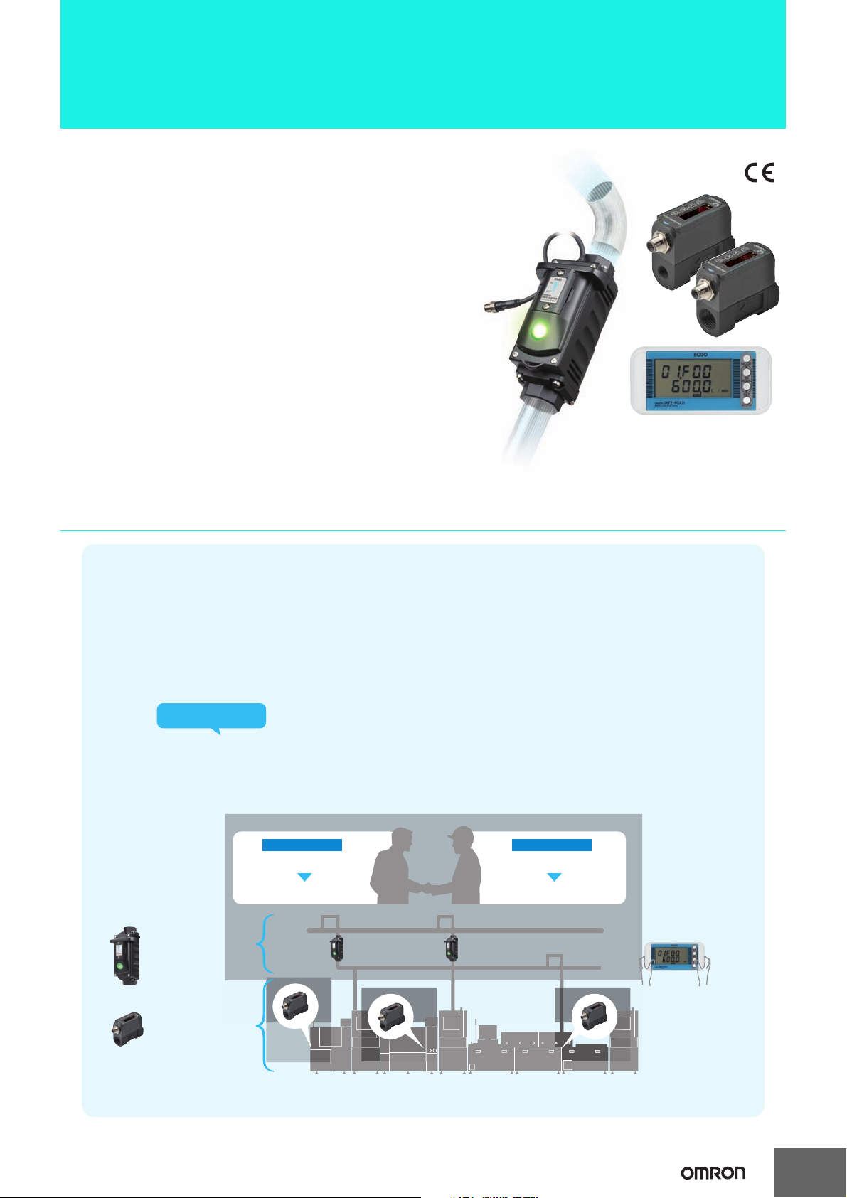
Visualize Air Flows, Pressures,
and Leakage to Save Energy
on Production Sites.
Visualization is required on both the supply
side and consumption side. This leads to lower
power consumption while maintaining quality.
Power supply side
Monitor and control supply quantities
Optimize supply quantities
Consumption side
Maintain production quality
Optimize usage quantities
Data logging
Compressed air at machines
D6FZ-FGT200/500
(200L/500L type)
Identify the waste that had previously been invisible to reduce the energy consumed for compressed air.
D6FZ-FGX21
1
Page 2
D6FZ
T
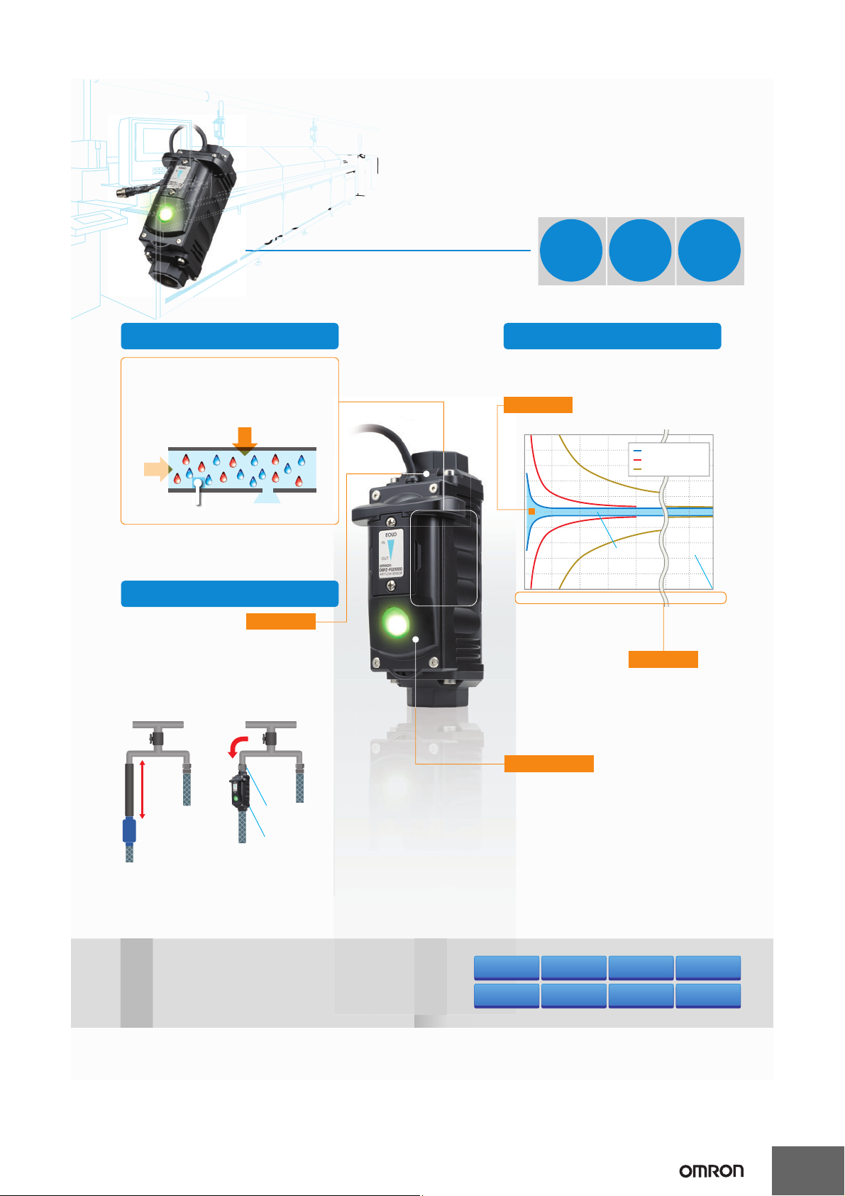
The Best Product to Measure
Compressed Air on Production Lines
D6FZ-FGS1000
Pipe size: R c1 (25A)
(A bushing can b e u sed to con vert down to 15A.)
Multi-sensing
Simultaneous Measurement of Flow,
Pressure, Leakage, and Temperature
The Sensor provides multiple sensing functions.
You can identify compressed air co nditions with
just one Sensor.
Flow
measurement
Simple Setup
Mountable to
Curved Pipes or Couplers
The built-in silencer eliminates ultrasonic noise
and turbulence. It eliminates the need for str aight
pipes to make installation work easy.
Previous pro ducts D6FZ-FGS
required.
A straig ht pipe wit h a
length that is 10 times
the open ing diam eter
is required.
Temperature
measurement
Straight
pipe not
Pressure measurement
Leakage
measurement
Silencer
Easy installation
with a cou pler.
Built-in suppressor to
suppress turbulence
and eliminate noise.
1
Leakage
2
Usage
3
Pressure
High Accuracy
Highly Accurate Flow Measurements
High measuring accuracy of ± 2% R.S. (at 50 L /min or less) is achi eved.
High accuracy
Flow Rate Measuring Accuracy
50
40
30
20
10
0
-10
Accuracy R.S . [%]
-20
-30
-40
-50
050100150200 95000 1000
* Data is base d on comparison for O MRON conditions
(November 2012).
Check the ac tual application environment before using
a Sensor.
Flow Measurements
over a Wide Range
A wide measurement range of 1 to 1,00 0 L/min
is achieved.
D6FZ-FGS (1000L/min max.)
Previous produ cts (200 L/min max.)
Previous produ cts (1000L/min max.)
Measuring accuracy
R.S. ±2 .0%
(at 50 L/ min or less)
Flow rate [L /min]
Wide range
Measurement range
1,000 L/min max.
Resists Oils and Mist
Ultrasonic sensor
A built-in ultrasonic sensor is used for flow measurements.
With high resistance to r usty pipes and oil flooded
compressors, you can install the Sensor almost anywhere.
Threshold values
(peak, bottom, and leak)
Alarm hold
Feature
Comparison
Flow
measurement
Curved pipe
mounting
Leakage
measurement
Resistant to oils and mist
Pressure
measurement
Station
connection
Tem perat ure
measurement
Multi-sensor
connection
Main
Features
Two analog outputs
Two pulse outputs
RS-485 communications
IP64
Operation indicator
2
Page 3
One analog out put
Two pulse outputs
RS-485 communications
IP65
Display
Threshold values (peak, bottom, and leak)
Peak/Bottom hold
Auto-tuning
Key lock
Main
Features
Feature
Comparison
Flow
measurement
Leakage
measurement
P
t
mea
sur
eme
t
g
ng
Res
ist
anttooi
ls
Station
connection
Multi-sensor
connection
Note: Omro n survey (as of June 2013)
Specifications are the same as the 1000L type.
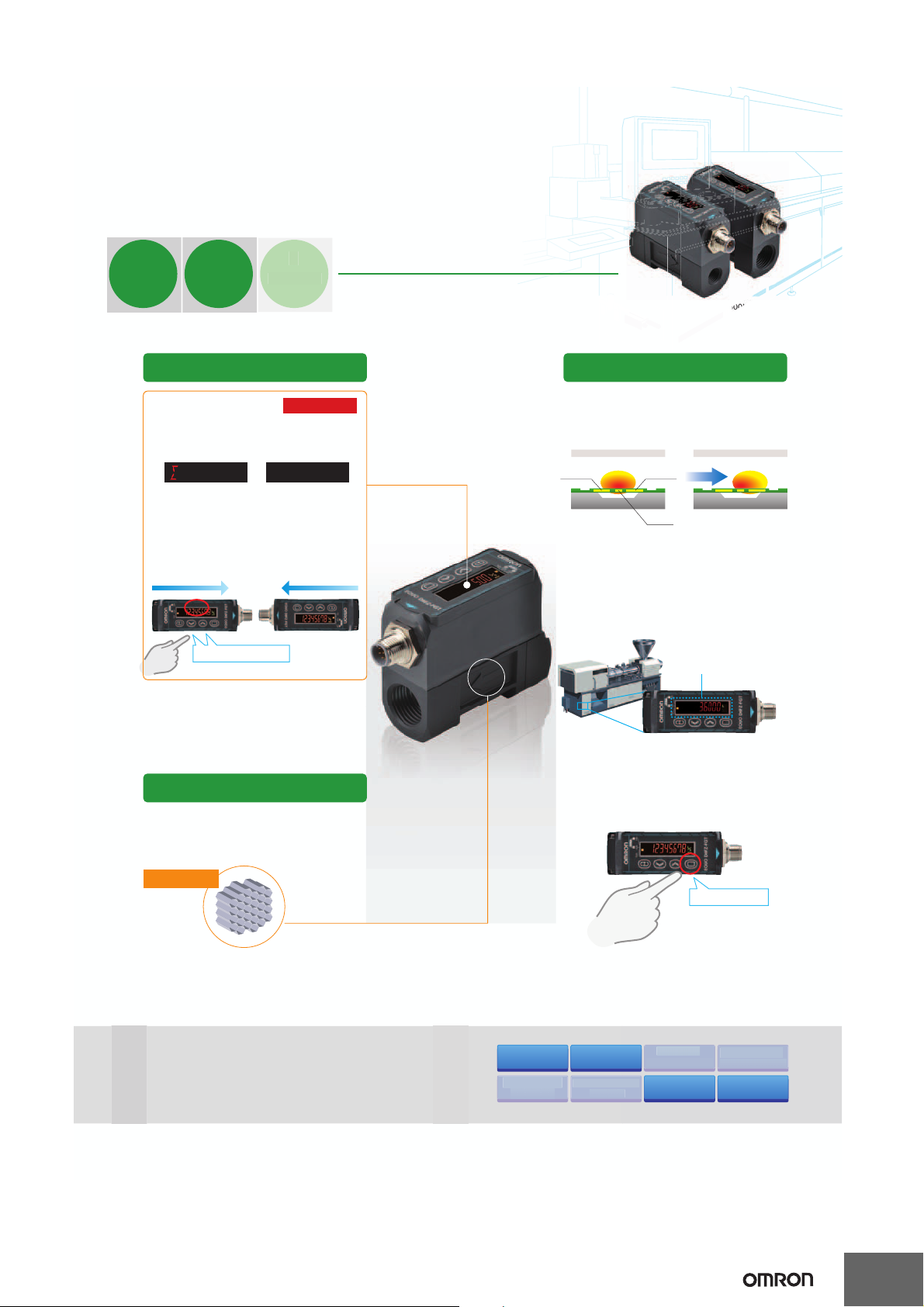
Ideal for Compressed Air Measurements
at
Machines
Leakage Measurement
A high measurement accur acy of ± 0.5% F.S. is achieved
at a low flow rate of less than 50 L /min.
This all ows you to identif y the air flow that is disc arded
as leakage when machines are not operating to save money.
Zero Reset
You can use the zero reset to id entif y seasonal
or day/night variations in the flow rates.
Display Reversal
You can reverse t he display direction to
match the installation dire ction.
Always use one of the specified installation
directions.
500L type
Pipe size: 15A ( Rc1/2)
200L type
Pipe size: 8 A (Rc1/4)
Note: According to OMRON investigation in June 2013.
Averaging c ount setting
ave
Clear tot al flow rat e
clr
11-segment 8-digit
LCD
The character s are easy to read, and the tot al flow rate
can be checked in a glance.
Easy to Read
Flow Straightener with Honeycomb Structure
A honeycomb structure effectively straightens
the flow to keep pressure loss low.
Other Features
Highly Accurate Flow Measurements
An OMRON MEMS chip is used to achieve the highest
accuracy in the industr y* of ± 2% F.S. (at 50 L/min or less).
High Accuracy
First in the industry!
*
Honeycomb structure
Press and hold.
Leakage on non-working days
(Satur day and Sunday) was 3 6 m
3
!
Press and h old to rever se.
Tem per atu re
sensor
Heater
element
Tem per atu re
sensor
Flow
With Flow Without Flow
Leakage
1
essu
Usage
2
D6FZ-FGT200/500
r
D6FZ
Curved pipe
mounti
and mist
ressure
measuremen
Tem perat ure
n
3
Page 4
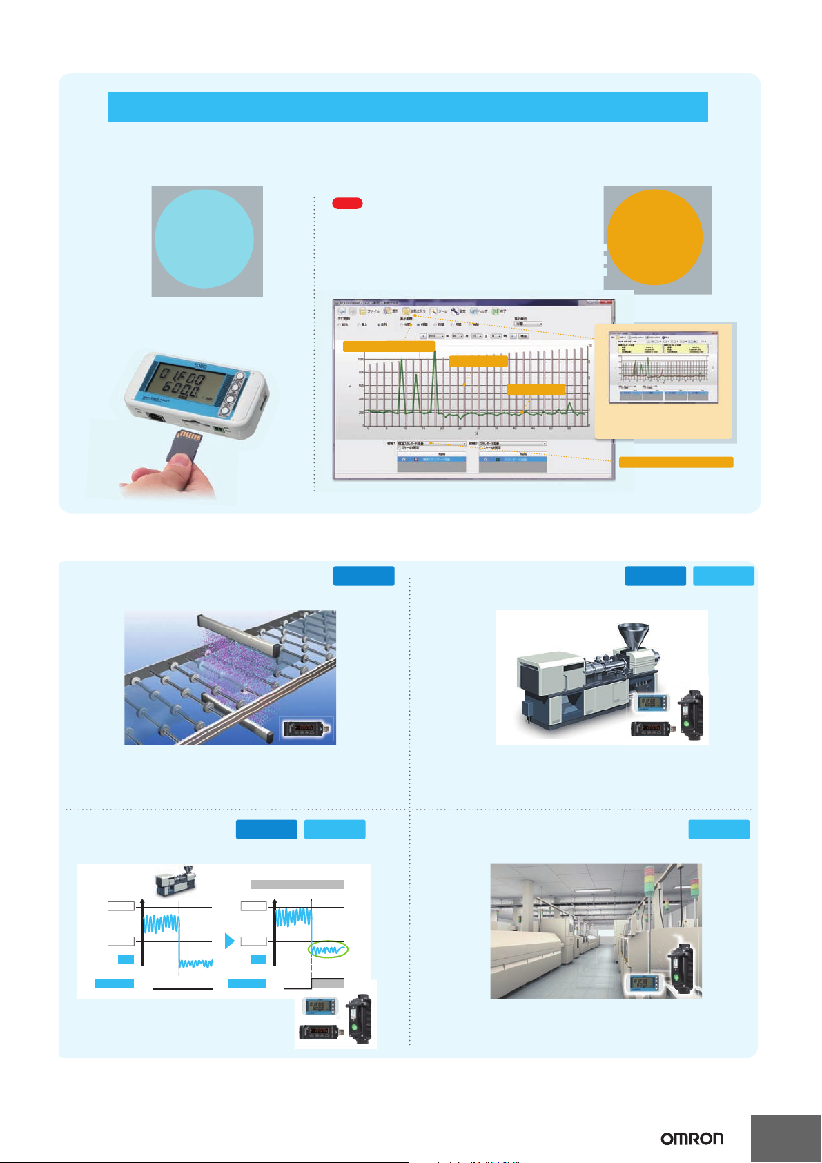
You can collect onsite data at an Air Flow Station data and use the Multi Data Viewer Light software to analyze
the data in your office to identify other locations for improvement on the production site.
On the
Production
Site:
Data monitoring and
storin g by Air Flow
Station
Multi Data Viewer Light
Display pe riod is easy to chang e.
Check boxes a llow you to display onl y the required data .
Total flow rate (bar graph)
Pressure (dotted line graph)
This sof tware d isplays data for sp ecifi c time pe riods , such as by t he minut e,
hour, or day. The tot al flow rat e is disp layed as a bar g raph and t he
moment ary flo w rate and pr essure are displ ayed with d otted li nes, so yo u can
see the overall situation at a glance.
Free The PC Sof tware
Download the P C Software Stati on Utility from th e following OMRON we bsite (http: //www.fa.omron .co.jp/stati on-u-e).
Start dat a logging with a sin gle
press of a but ton.
Save the data to
an SD memory card.
The Air Flow Station enables
easy data logging.
The PC Software Easily Analyzes Logged Data
You can use comp arative dis plays with
previously logged data.
For example, s ide-by-side co mpariso n of flow
rates by the day f or different mont hs is possible.
In the Office:
Data stor ing and
analyzing
on a computer
By stopping the supply of compressed air with a solenoid valve when there
is no workpiece, compressed air usage is reduced. At the same time, the
Flow Sensor monitors the quantity of supplied compressed air to ensure
that it is within the specified range. Therefore, the Sensor helps maintain
and improve quality.
By giving priority to the monitoring of molding machines and
other machines that use large quantities of compressed air,
energy is efficiently saved.
Set the leak threshold value to identify when
repairs for leaks are required.
Monitor consumption and pressure fluctuations for each
production line to identify bottleneck lines or machines to
implement onsite improvements and save energy.
During operation
ON
OFF
When operation is stopped
Upper limit
Lower limit
leak
Leak output
During operation
When the leak increases
ON
OFF
When operation is stopped
Upper limit
Lower limit
leak
Leak output
You can save energy in a variety of applications.
Stop Ionizer Idling
D6FZ-FGT
Flow Management for
Molding Machines
D6FZ-FGT D6FZ-FGS
Leakage Management
for Machines
D6FZ-FGT D6FZ-FGS
Flow and Pressure
Management for Production Lines
D6FZ-FGS
D6FZ
,
4
Page 5
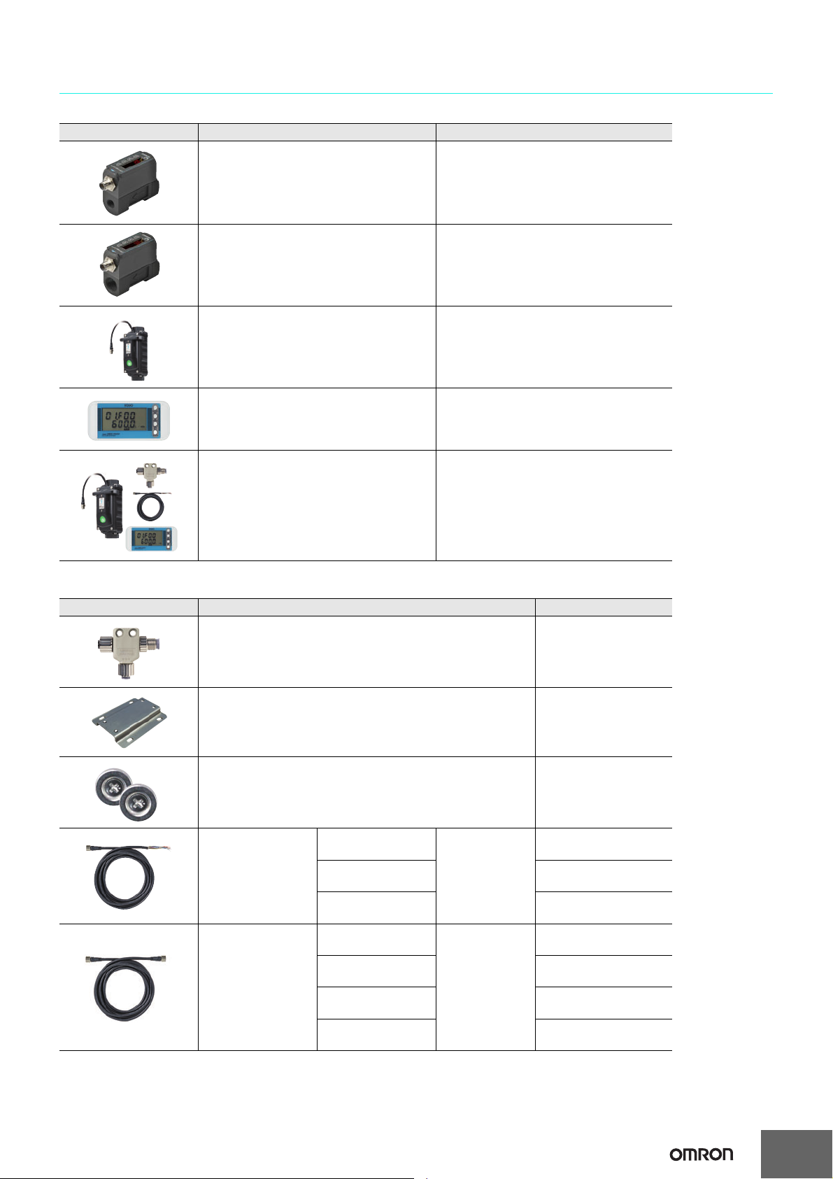
Specifications
Units
Appearance Product name Model
200L-type Air Flow Sensor D6FZ-FGT200
500L-type Air Flow Sensor D6FZ-FGT500
D6FZ
1000L-type Air Flow Sensor
(cable length: 0.2 m)
Air Flow Station
(cable length: 1.5 m, including T-branch
Connector cable)
1000L-type Air Flow Sensor Set
• 1000L-type Air Flow Sensor
• Air Flow Station
• T-branch Connector
• Cable with Connector on One End (3 m)
D6FZ-FGS1000
D6FZ-FGX21
D6FZ-FGS1000-S
Options (Sold Separately)
Appearance Product name Model
T-branch Connector D6FZ-FC02
(D6FZ-FGT Air Flow Sensor only)
Mounting Bracket
• Mounting Bracket: 1
• Phillips screws (M3): 4
D6FZ-FC03
(D6FZ-FGX21 Air Flow Station only)
Mounting magnets
• Mounting magnets: 2
• Phillips screws (M3): 2
Cable with Connector
on One End
Cable with
Connectors on Both
Ends
* When magnets are used, the maximum vibration resistance is 55 Hz.
*
Cable length: 3 m
Cable length: 10 m D6FZ-JD10A
Cable length: 20 m D6FZ-JD20A
Cable length: 3 m
Cable length: 5 m D6FZ-JD5B
Cable length: 10 m D6FZ-JD10B
Cable length: 20 m D6FZ-JD20B
ZN9-EM01-S
D6FZ-JD3A
M12 connector
(8-pin)
D6FZ-JD3B
M12 connector
(8-pin)
5
Page 6

D6FZ
Ratings
Air Flow Sensor
Item Model D6FZ-FGT200 D6FZ-FGT500
Applicable fluid Air or nitrogen (N2)
Maximum working pressure 0.75 MPa (withstand pressure: 1.5 MPa)
Measurement range
Measurement range for specified accuracy
*2
Display resolution
Accuracy
Temperature characteristic ±3% F.S.
Repeat accuracy ±1% F.S.
Operating temperature Operation: −10 to 60°C, Storage: −20 to 70°C (with no condensation or icing)
Operating humidity Operation: 25% to 90% RH, Storage: 0% to 90% RH (with no condensation or icing)
Shock resistance (destruction) 150 m/s2 3 times each in six directions (up/down, left/right, forward/backward)
Pressure loss 2 kPa max. 4 kPa max.
Power supply voltage 12 to 24 VDC ±10% ripple (p-p): 10% max.
Current consumption 120 mA max.
Functions
Indications
Outputs
Degree of protection IP65
Installation Direction and Straight Pipe
Section
Connection pipe diameter Rc1/4 (8A) Rc1/2 (15A)
Materials Main unit: PBT, Flow channel: Zinc
Dimensions 30 × 77 × 63.7 mm (W×D×H)
Weight (in package) Approx. 400 g (500 g)
Accessories Instruction Sheet
*1. Clean dry gas (Must not contain large particles, e.g. dust, oils, or mist.)
*2. The flow rates are converted for the following conditions. Standard flow rate (std): 1 atmospheric pressure (101.3 kPa) at 20°C (default setting)
*3. To prevent chattering, a judgement output is made when the judgement continues for one minute or longer.
*4. The accuracy will depend on the length of the straight pipe section. Refer to Flow rate accuracy characteristics for a length of straight pipe on page
*2
Normal flow rate (nor): 1 atmospheric pressure (101.3 kPa) at 0°C
10 for details.
*2
*2
Output
interfaces
Output values
Analog
ON/OFF
RS-485
0 to 200 L/min 0 to 500 L/min
2 to 200 L/min 5 to 500 L/min
1 L/min
±2.0% F.S. at 50 L/min or higher
±0.5% F.S. at less than 50 L/min
Momentary flow, total flow, display reversal, zero point adjustment, peak and bottom hold, key
lock, eco mode, scaling (analog output), judgement hysteresis, and teaching
11-segment digital display (red); RUN, FUN, and THR (yellow); Out1 and Out2 (yellow); key lock
(yellow); flow unit (green); and flow unit on reversed display (yellow)
Current output: 4 to 20 mA (1 output), Maximum load resistance: 300 Ω
Open-collector output (2 outputs): 26.4 VDC 50 mA max.
ON residual voltage: 2 V max. (Outputs can be selected from judgement output, pulse output,
and Sensor error output.)
2-wire half-duplex communications with start-stop synchronization
Baud rate: 9.6, 19.2, 38.4, or 115.2 kbps, Data bit length: 7 or 8 bits, Stop bit length: 1 or 2 bits,
Parity: none, even, or odd, Terminating resistance (120 Ω): ON/OFF, Communications protocol:
Conforms to CompoWay/F.
Momentary flow, total flow, judgement output *3, and Sensor error output
A straight pipe section must be provided during installation and piping if the Sensor is installed
horizontally and the display is on the top.
*1
*4
6
Page 7

D6FZ
Item Model D6FZ-FGS1000
Applicable fluid Air or nitrogen (N2)
Working pressure 0.99MPa max.
Detection
range
Resolution
Accuracy
Detection
range
Accuracy
Detection
range
Accuracy
Measurements
Resistance
to
environment
*1
Flow
Pressure
Temperature
Operating temperature
Operating humidity
Vibration resistance
(destruction)
Shock resistance (destruction)
Pressure loss
Power supply voltage
Power consumption 2 W max.
Measurement cycle Approx. 62.5 ms
Display
Outputs
Display method
Displayed contents
Output
interfaces
Output values
Analog
ON/OFF
RS-485
Degree of protection IP64 (Except when switch cover is removed.)
Wiring connection M12 connector (8-pin)
Connection pipe diameter Rc1 (25A) (Bushing enables conversion to 15A or 20A.)
Materials Cable: PVC (polyvinylchloride); Main unit: Aluminum die-cast; Display: Acrylic
Dimensions 64 × 93 × 195 mm (W×D×H) (excluding flange)
Weight (in package) Approx. 1.2 Kg (Approx. 1.7 Kg)
Accessories Instruction Sheet
*1. Flow rates are converted to 1 atmospheric pressure (101.3 kPa) at 20°C.
*2. Does not include pressure and temperature accuracy. Conversion accuracy to the standard flow is ±2.5% of reading (at 20°C, 0.5 MPa).
*3. Always ground the 0 V terminal, and do not ground the 24 V (+) terminal. There is a risk of malfunction.
*4. The analog output is the momentary standard flow rate and pressure.
*5. The total standard flow for the pulse output can be set to 1, 10 (default), 100, or 1,000 L (std) per pulse.
1 to 1,000 L/min (std)
0.1 L/min
±2.0% of reading at 50 L/min (std) or higher
±0.1% F.S. at less than 50 L/min
*2
*2
0 to 0.99 MPa
2% F.S.
−10 to 60°C
±1.5% (absolute temperature)
−10 to 60°C (with no condensation or icing)
35% to 85% RH (with no condensation or icing)
10 to 55 Hz with a 0.7-mm double amplitude or acceleration of 50 m/s2 for 80 min each in X, Y,
and Z directions
150 m/s2 3 times each in six directions (up/down, left/right, forward/backward)
Direct piping: 10 kPa max. (0.5 MPa, at maximum flow)
Using Coupler (TL model from Nagahori Industry Co., Ltd.): 10 kPa max. (0.5 MPa, at maximum
flow)
For one Sensor: 16 to 24 VDC ±10%, ripple (p-p): 10% max.,
For multiple Sensors: 24 VDC ±10%, ripple (p-p): 10% max.
*3
Status display with 2-color LED (lit or flashing)
Presence of power, air flow, and error alarm
Current output: 4 to 20 mA (2 outputs),*4 Maximum load resistance: 270 Ω
Open-drain output (2 outputs),*5 24 VDC 50 mA max.
ON residual voltage: 1.5 V max., OFF leakage current: 50 μA max.
2-wire half-duplex communications with start-stop synchronization
Baud rate: 115.2 kbps (fixed), Data bit length: 8 bits (fixed), Stop bit length: 1 bit (fixed), Parity:
even (fixed), Communications protocol: Conforms to CompoWay/F.
Momentary standard flow, total standard flow, pressure, and Sensor error output
7
Page 8

D6FZ
Air Flow Station
ItemModel D6FZ-FGX21
Connectable Sensors D6FZ-FGT200, D6FZ-FGT500, and D6FZ-FGS1000
Maximum number of connected Sensors 8
Indications 7-segment 5-digit 2-row LCD, auxiliary information indicators
Recording interval 1 s, 2 s, 5 s, 10 s, 20 s, 30 s, or 1 min
Displayed data Momentary flow rate, total flow rate, pressure, temperature, and billing amount/CO2 conversion
Recorded data Momentary flow rate, total flow rate, volume flow rate, pressure, and temperature
Calculation functions Conversion of total flow rate to billing amount/CO2
Recording modes Continue Mode*2 and Ring Mode
External output Alarm output (photocoupler output)
Communications interface Ethernet (10Base-T or 100Base-TX)
Internal storage device
External storage device
Power supply voltage DC input: 24 VDC ±10%, ripple (p-p): 10% max.
Current consumption 80 mA max.
Operating temperature
Operating humidity 35% to 85% RH (with no condensation or icing)
Storage humidity/temperature −15 to 60°C, 20% to 85% RH (with no condensation or icing)
Insulation resistance 20 MΩ (at 500 VDC)
Withstand voltage 1,000 VAC, 50/60 Hz for 1 min
Vibration resistance (destruction)
Shock resistance (destruction) 150 m/s2 3 times each in six directions (up/down, left/right, forward/backward)
Material ABS
Degree of protection IP30
Mounting method Magnet mounting, screw mounting, or hooks
Dimensions 117.2 × 24.6 × 56.8 mm (W×D×H) (excluding protruding parts)
Weight (in package) Approx. 150 g (Approx. 500 g)
Accessories Instruction Sheet, Startup Guide, Connection Cable,*7 Alarm Output Connector
*1. Up to 8 Sensors can be connected when the recording cycle is 2 seconds or longer; up to 4 Sensors can be connected when the recording
cycle is 1 second.
*2. Data is automatically written to the SD memory card when the internal memory reaches its capacity and recording continues until the SD
memory card capacity is reached. Recording stops if there is no SD memory card inserted, when the internal memory capacity is reached, or
when the SD memory card is write protected. (Recording can be resumed after inserting an SD memory card and outputting the data to it by
pressing a button.) The default is Continue Mode. Use the PC Software to change the recording mode.
*3. Recording of the latest measured values continues until the internal memory reaches its capacity. (If the internal memory capacity is exceeded,
data is overwritten from the oldest data in the memory.)
*4. An alarm is output when the upper or lower limit of the air flow that was set in threshold setting mode is exceeded.
*5. You can temporarily read and write data with an SD card that complies with SD/SDHC card standards and was made by another company,
but the SD card may suddenly not be recognized, preventing you from accessing the data.
*6. When mounting the Sensor with magnets, be sure to install it in a location where it will not be subjected to shock.
*7. A T-branch connector to connect to D6FZ-FC02.
*8. OMRON's XW4B-02B1-H1 Connector.
*1
*3
*4
Internal memory: Approx. 4,200 data items when 1 Sensor is connected, Approx. 650 data items
when 8 Sensors are connected.
SD card (to save measured values and to save/read set values), Recommended SD card: HMCSD291 (manufactured by OMRON)
*5
Without Ethernet: −10 to 40°C (with no condensation or icing), with Ethernet: 0 to 40°C (with no
condensation or icing)
10 to 150 Hz with a 0.7-mm double amplitude or acceleration of 50 m/s
2
for 80 min each in X, Y,
and Z directions
*6
*8
8
Page 9

Connections
A Cable with Connector on One End
B Cable with Connectors on Both Ends
24-V power supply
or
or
Sensor setup
Data display
Data logging
A
B
A
A
Air Flow Station Connections
24-V power supply
Terminal
block
Analog output
Pulse output
PLC
PLC Connections
8 max.
8 max.
Main pipe Main pipe
Sensor settings
Displayed data
Data logging
Etherne t
24-V power
supply
A
A
BB
B
BBB
B
B
B
Terminal block
RS-485
RS-485
PLC
24-V power
supply
RS-485 Connections to Air Flow Station RS-485 Connections to PLC
Refer to the user’s manuals for the Wireless Unit and Air Flow Sensors for
detailed information on connections.
Connects to
up to 2 Sensors.
Main pipe
Wireless Unit Master (LAN)
For detailed specifications, consult your OMRON sales representative.
WZ-MLAN01
Wireless Unit Slave (Pulse Count)
WZ-SP01
Ethernet
A
A
The Triple Reliability of the 920 MHz Band
Compared
to the 2.4
GHz band:
The reliability of a
longer communications
distance.
The reliability of easier
bending of waves bend
around objects.
The reliability of less
interference from other
communications devices.
Connection Diagrams
With One Sensor
Data Communications with Multiple Sensor Connections
D6FZ
Wireless Data Collection
9
Page 10

Engineering Data
* Note: With direct piping.
0
0 200 400 600 800 1000
1
2
3
4
5
6
Pressure loss (kPa)
Flow rate (L/min (std))
Atmospheric pressure
0.3 MPa
0.5 MPa
1.0 MPa
max. usable flow rate
020010050 150
Pressure loss (kPa)
Flow rate (L/min (std))
atmospheric pressure
0.5MPa
0.75MPa
0
1
2
0500100 200 300 400
Pressure loss (kPa)
Flow rate (L/min (std))
atmospheric pressure
0.5MPa
0.75MPa
0
2
4
1
3
030025015010050 200
Precision F.S. [%]
Pipe length [mm]
*2
±10%
±8%
±6%
±4%
±2%
±0%
12
10
8
6
Applied tube
diameter
*1
030025015010050 200
Precision F.S. [%]
±10%
±8%
±6%
±4%
±2%
±0%
20A
16
12
10
Applied steel pipe
/tube diameter
*1
Pipe length [mm]
*2
D6FZ
Pressure Loss* (Typical)
D6FZ-FGS1000
D6FZ-FGT200
Minimum and Maximum Flow Rate Conversion Table
(Typical)
D6FZ-FGS1000
Temperature
[°C]
20
25
30
Pressure
[MPa]
Minimum flow
rate
[L/min (std)]
0.3 3.96 667.37
0.5 5.93 999.94
0.7 7.91 1000.00
0.3 3.89 656.17
0.5 5.83 983.17
0.7 7.78 1000.00
0.3 3.83 645.35
0.5 5.74 966.96
0.7 7.65 1000.00
Maximum flow
rate
[L/min (std)]
Flow rate accuracy characteristics for a length of straight
pipe
D6FZ-FGT Only
The following graph shows the flow rate accuracy characteristics for
a length of straight pipe (reference information).
D6FZ-FGT200
D6FZ-FGT500
D6FZ-FGT500
Straight Steel Pipe with Same Opening Diameter as Sensor
*1
Tube
Steel pipe with
different
*1
diameter
Straight steel
pipe length
*1
Tube
*2
Straight steel
pipe length
*2
Steel pipe with
different diameter
*1
10
Page 11

Safety Precautions
• Mounting the body horizontally
• Control panel Upward
• Mounting the body Vertically • Control panel Downward
Read the warranty and limitations of liability information.
Air Flow Sensors
Warning
This product cannot be used to detect people either
directly or indirectly for the purpose of ensuring
safety.
Do not use the product as a detector for personal
safety.
The use of flammable gases may cause an
explosion.
Do not use the product in the presence of flammable
gases.
Electric shock may occur. Do not connect the
product to an AC power supply.
Caution
Do not use the product in an ambient atmosphere or
environment that exceeds the ratings.
Injury may occur due to an explosion.
Flow rates and pressures must be within the
specified working ranges.
<D6FZ-FGT only>
If water drops, oil, mist, or dust enters the product, it
may result in measurement error or damage. Use
clean gas. Dust and mist can affect the
characteristics of Sensor or damage the Sensor. Install a filter
and mist separator on the upstream tube. Also, install the
product after removing any dust in the pipes with an air blow or
other means.
Precaution for mounting
Mounting position
• Be sure to mount the body horizontally, otherwise the
• Don't mount the body facing the control panel downward.
<Correct mounting>
<Incorrect mounting>
Flowing direction
• An arrow in the side of the body indicates the direction
• Be sure to check the direction of the arrow before mounting.
• Mounting in the opposite direction causes mis-
<The indication of the body>
D6FZ
detection accuracy might be worse.
Otherwise, the mist and dust in the pipe accumulates and it
might cause breakdown.
where air flows.
measurement.
DownstreamUpstream
Precautions for Correct Use
Precaution for piping
D6FZ-FGT Only
Applicable Opening Diameter: D6FZ-FGT200: 8A, D6FZFGT500: 15A
Always use a steel straight or elbow pipe with the same
opening diameter. If a steel pipe with a different opening
diameter or an air tube joint is required, you can reduce
adverse influences by providing a section of straight pipe with
the same opening diameter just before and after the Sensor.
Refer to Flow rate accuracy characteristics for a length of
straight pipe on page 10 for the required straight pipe length
and measurement accuracy.
Indication of flowing direction
<The relationship between flowing direction and mounting
direction>
Flowing direction
Upstream
Downstream
Indication of flowing direction
Steel pipe
Air Flow Station
Warning
The mounting magnets provided with the product
have strong magnetism. If the product is mounted
using these magnets, anyone wearing a heart
pacemaker must not operate the product. Also, the
product must not be brought into the proximity of such a
person.
This product contains lithium batteries. Serious
injury may occur due to fire or explosion. Do not
attempt to disassemble the product, deform it by
applying pressure, heat it to a high temperature
(100°C or higher), or incinerate it for disposal.
11
Page 12

D6FZ
(Unit: mm)
Unspecified dimensional tolerances: Tolerance class IT16
Mounting Hole Dimensions
63.7
30
33.7
77
12.65
70
(60)
89.65
Rc1/4,
Effective
depth: 10 mm
49.5
±0.1
16
±0.1
7
Four, M3;
Effective
depth: 5 mm
30
Rc1/4,
Effective
depth: 10 mm
15
47
15
Four, 3.2 dia. ±0.1 holes
16
±0.1
49.5
±0.1
D6FZ-FGT200
Mounting Hole Dimensions
63.7
30
33.7
77
12.65
70
(60)
89.65
Rc1/2,
Effective
depth: 10 mm
49.5
±0.1
16
±0.1
7
Four, M3;
Effective
depth: 5 mm
30
Rc1/2,
Effective
depth: 10 mm
15
47
15
Four, 3.2 dia. ±0.1 holes
16
±0.1
49.5
±0.1
D6FZ-FGT500
131.5
45.8 59.2
64
88
Switch cover
Ferrite core
195
28
93
200±50 43
14.9 dia.
M12
Rc1 (both sides)
DIP switch
Rotary switch
Switch Cover
Removed
Status indicator
D6FZ-FGS1000
Dimensions
Air Flow Sensor
12
Page 13

Air Flow Station
2-M3
2-4 dia.
56.8
24.60.7
117.2
Reset switch
40
40
60
49.4
48.6
60
Screw catch-holes
Screw catch-hole dimensions
Mounting screw hole
dimensions
Mounting screw holes, Two M3 holes; Hole depth: 4
Mode Key
LAN port
SD memory
card slot
Display
T-branch
connector plug
Up Selection Key
Down Selection Key
SET/REC/STOP Key
Standard length: 1.5 m
8.7
16.7
21
Alarm output terminal
D6FZ-FGX21
T-branch Connection Cables
13.6
32.1
15
24.7
13.6 17.7
10
12
4.5-dia. through-hole
8 dia. (countersinking depth: 2)
M12 plug
CN0
CN1
CN2
14.9-dia.
18
14.9 dia.
4.5-dia. through-hole
8-dia. (Countersunk hole depth: 2)
Back
(56)
M12 socket
M12 socket
M12 socket
M12 socket
M12 socket
39.5
15-dia.
26.8
14.9-dia.
43
26.8
L
M12 plug
Plate
T-branch Connector
D6FZ-FC02
Cables with Connector on One End
D6FZ-JD3A (L = 3 m)
D6FZ-JD10A (L = 10 m)
D6FZ-JD20A (L = 20 m)
Cables with Connectors on Both Ends
D6FZ-JD3B (L = 3 m)
D6FZ-JD5B (L = 5 m)
D6FZ-JD10B (L = 10 m)
D6FZ-JD20B (L = 20 m)
Mounting Bracket
D6FZ-FC03
D6FZ
8.5
4
4-3.5
48
40
5.25 49.5
Four, 3.2-dia. holes
60
40
4-3
8-R1.75
16 16
39.5
26.8
M12 socket
15-dia.
Plate
5
25
1
L
13
Page 14

Terms and Conditions Agreement
2016.11
Read and understand this catalog.
Please read and understand this catalog before purchasing the products. Please consult your OMRON representative if you
have any questions or comments.
Warranties.
(a) Exclusive Warranty. Omron’s exclusive warranty is that the Products will be free from defects in materials and workmanship
for a period of twelve months from the date of sale by Omron (or such other period expressed in writing by Omron). Omron
disclaims all other warranties, express or implied.
(b) Limitations. OMRON MAKES NO WARRANTY OR REPRESENTATION, EXPRESS OR IMPLIED, ABOUT
NON-INFRINGEMENT, MERCHANTABILITY OR FITNESS FOR A PARTICULAR PURPOSE OF THE PRODUCTS. BUYER
ACKNOWLEDGES THAT IT ALONE HAS DETERMINED THAT THE
PRODUCTS WILL SUITABLY MEET THE REQUIREMENTS OF THEIR INTENDED USE.
Omron further disclaims all warranties and responsibility of any type for claims or expenses based on infringement by the
Products or otherwise of any intellectual property right. (c) Buyer Remedy. Omron’s sole obligation hereunder shall be, at
Omron’s election, to (i) replace (in the form originally shipped with Buyer responsible for labor charges for removal or
replacement thereof) the non-complying Product, (ii) repair the non-complying Product, or (iii) repay or credit Buyer an amount
equal to the purchase price of the non-complying Product; provided that in no event shall Omron be responsible for warranty,
repair, indemnity or any other claims or expenses regarding the Products unless Omron’s analysis confirms that the Products
were properly handled, stored, installed and maintained and not subject to contamination, abuse, misuse or inappropriate
modification. Return of any Products by Buyer must be approved in writing by Omron before shipment. Omron Companies shall
not be liable for the suitability or unsuitability or the results from the use of Products in combination with any electrical or
electronic components, circuits, system assemblies or any other materials or substances or environments. Any advice,
recommendations or information given orally or in writing, are not to be construed as an amendment or addition to the above
warranty.
See http://www.omron.com/global/ or contact your Omron representative for published information.
Limitation on Liability; Etc.
OMRON COMPANIES SHALL NOT BE LIABLE FOR SPECIAL, INDIRECT, INCIDENTAL, OR CONSEQUENTIAL DAMAGES,
LOSS OF PROFITS OR PRODUCTION OR COMMERCIAL LOSS IN ANY WAY CONNECTED WITH THE PRODUCTS,
WHETHER SUCH CLAIM IS BASED IN CONTRACT, WARRANTY, NEGLIGENCE OR STRICT LIABILITY.
Further, in no event shall liability of Omron Companies exceed the individual price of the Product on which liability is asserted.
Suitability of Use.
Omron Companies shall not be responsible for conformity with any standards, codes or regulations which apply to the
combination of the Product in the Buyer’s application or use of the Product. At Buyer’s request, Omron will provide applicable
third party certification documents identifying ratings and limitations of use which apply to the Product. This information by itself
is not sufficient for a complete determination of the suitability of the Product in combination with the end product, machine,
system, or other application or use. Buyer shall be solely responsible for determining appropriateness of the particular Product
with respect to Buyer’s application, product or system. Buyer shall take application responsibility in all cases.
NEVER USE THE PRODUCT FOR AN APPLICATION INVOLVING SERIOUS RISK TO LIFE OR PROPERTY OR IN LARGE
QUANTITIES WITHOUT ENSURING THAT THE SYSTEM AS A WHOLE HAS BEEN DESIGNED TO ADDRESS THE RISKS,
AND THAT THE OMRON PRODUCT(S) IS PROPERLY RATED AND INSTALLED FOR THE INTENDED USE WITHIN THE
OVERALL EQUIPMENT OR SYSTEM.
Programmable Products.
Omron Companies shall not be responsible for the user’s programming of a programmable Product, or any consequence
thereof.
Performance Data.
Data presented in Omron Company websites, catalogs and other materials is provided as a guide for the user in determining
suitability and does not constitute a warranty. It may represent the result of Omron’s test conditions, and the user must correlate
it to actual application requirements. Actual performance is subject to the Omron’s Warranty and Limitations of Liability.
Change in Specifications.
Product specifications and accessories may be changed at any time based on improvements and other reasons. It is our
practice to change part numbers when published ratings or features are changed, or when significant construction changes are
made. However, some specifications of the Product may be changed without any notice. When in doubt, special part numbers
may be assigned to fix or establish key specifications for your application. Please consult with your Omron’s representative at
any time to confirm actual specifications of purchased Product.
Errors and Omissions.
Information presented by Omron Companies has been checked and is believed to be accurate; however, no responsibility is
assumed for clerical, typographical or proofreading errors or omissions.
In the interest of product improvement, specifications are subject to change without notice.
OMRON Corporation
Industrial Automation Company
http://www.ia.omron.com/
(c)Copyright OMRON Corporation 2016 All Right Reserved.
 Loading...