


MEMS Flow Sensor
D6F-series
User’s Manual
MEMS Flow Sensor
A286-E1-01

INDEX
1 OUTLINE ........................................................................................................................................ 2
2 WHAT IS A FLOW SENSOR? ....................................................................................................... 2
3 STRUCTURE ................................................................................................................................. 2
3.1 B
3.2 F
ASIC COMPOSITION OF FLOW SENSORS .................................................................................... 2
LOW SENSOR PRODUCT LINEUP .............................................................................................. 3
4 OPERATING PRINCIPLE .............................................................................................................. 4
4.1 B
4.2 D
ASIC STRUCTURE OF MEMS FLOW SENSOR CHIP ..................................................................... 4
ETECTING PRINCIPLE OF MASS FLOW SENSOR .......................................................................... 6
5 PRODUCT FEATURES ................................................................................................................. 7
5.1 CHARACTERISTICS OF FLOW SENSORS ...................................................................................... 7
5.1.1 Detection range of flow sensors ...................................................................................... 8
5.1.2 Output signal (operating characteristics) ......................................................................... 8
5.1.3 Permission pressure performance .................................................................................. 9
5.1.4 Repeatability .................................................................................................................... 9
6 USAGE OF FLOW SENSOR ........................................................................................................ 9
6.1 ELECTRICAL CONNECTION ......................................................................................................... 9
6.2 P
ORT STYLE AND INSTALLATION METHOD .................................................................................. 10
6.2.1 Screw type ..................................................................................................................... 10
6.2.2 Quick fastener type ........................................................................................................ 10
6.2.3 Manifold mount type ....................................................................................................... 11
6.2.4 Bamboo type.................................................................................................................. 12
6.3 A
TTENTION FOR PIPING AND CONNECTION ................................................................................ 13
6.3.1 Cleanup of the inflow gas .............................................................................................. 13
6.3.2 S
tabilization.................................................................................................................... 13
6.3.3 Measurement of high flow ............................................................................................. 13
6.3.4 Consideration of the laminar flow .................................................................................. 14
6.4 T
HE INFLUENCE OF ENVIRONMENT ........................................................................................... 14
6.4.1 Temperature characteristics .......................................................................................... 15
6.4.2 The influence of dust ..................................................................................................... 15
6.4.3 The influence of pressure and temperature .................................................................. 16
6.4.4 The influence of the mounting direction ........................................................................ 16
6.4.5 Output changes in various gases .................................................................................. 17
6.4.6 The behavior in over flow rate range ............................................................................. 17
6.4.7 The influence of humidity .............................................................................................. 17
6.5 A
PPLICATION EXAMPLE ............................................................................................................ 18
7 GLOSSARY ................................................................................................................................. 19
8 WARRANTY AND LIMITED LIABILITY ...................................................................................... 21
1 D6F-series MEMS Flaw Sensor User’s Manual (A286)

Time
Pressure
Drop
Consumption
Size Element
Endurance
Heat Wire
× ○ △
△ ○ ○
○
△
× ○
○ ○
○
○
○
×
×
× △ △ ×
×
×
△ △
○ ○
△
△
○
1 Outline
This application note explains the features, basic usage and some notices of OMRON MEMS
Flow Sensor (D6F series) before use.
2 What is a Flow Sensor?
A flow sensor is a sensor that detects the flow rate and flow velocity of a gas. In general, there are
various types of flow sensors, such as a propeller type, a float type, an ultrasonic type, a hot wire
type, and so on. OMRON flow sensors adopt a MEMS heat wire type, and have relatively excellent
characteristics in comparison with other types of flow sensors.
Table1. Various Types of Flow Sensor and Features
OMRON Conventional Sensors
Type
Sensitivity
Response
Current
Sensing
Mechanical
Propeller Float Ultrasonic Heat Wire MEMS
Volumetric Flow Sensor Mass Flow Sensor
3 Structure
3.1 Basic composition of flow sensors OMRON flow sensors are dedicated to gas, it can be used for detecting the mass flow of
various types of gases. The basic composition of flow sensors consist of a MEMS flow sensor
chip that can detect the flow rate, the amplifier circuit for amplifying sensor output and the
optimized flow path that is designed for each application by CAE (Computer Aided Engineering).
Optimizing these three compositions is very important because gas flow is a vector volume.
D6F-series MEMS Flaw Sensor User’s Manual (A286) 2
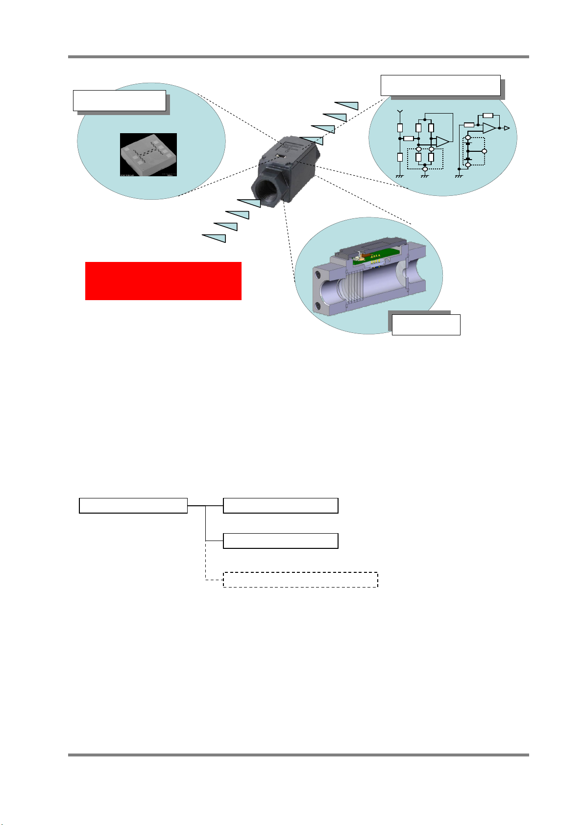
MEMS Flow Sensor
Mass Flow Sensor
Flow Velocity Sensor
D6F-PH Series
Differential Pressure Sensor
D6F
A /
AB /
N /
L /-P□ Series
Driving / Amp. Circuit
MEMS
Flow Path
Flow Chip
(Sensing)
Optimizing design of the three
compositional units is important.
Fig. 1 Example of Internal Structure of Flow Sensor
3.2 Flow Sensor Product Lineup OMRON’s flow sensor lineup consists of three categories, Mass flow sensors that output a flow
rate, Flow velocity sensors that output a flow velocity and Differential pressure sensors that can
detect a small pressure drop.
For more information about differential pressure sensors, please refer to the application notes of
MDMK-13-0196.
(Heater / Output)
-□
D6F-V□ / -W□ Series
A flow sensor‘s shape and size will differ depending on the type of gas to be measured, the flow
rate, and the port style. Please refer to the datasheet at the following URL for more information.
http://www.omron.com/ecb/products/search/?cat=5&did=1&prd=mems-flow&lang=en
3 D6F-series MEMS Flaw Sensor User’s Manual (A286)
-□
-□
-□
Medium
Table 2 Outline Specifications of D6F series
Series Name
D6F-□A1 Air 1 ~ 2 lpm Mass Flow Bamboo Joint Compact Size
D6F-□N2 City gas*1 1 ~ 5 lpm Mass Flow Rc1/4 Screw Flammable Gas
D6F-02L2 LPG 2 lpm Mass Flow Rc1/4Screw Flammable Gas
D6F-03A Air 3 lpm Mass Flow M5 Screw High Response Time
D6F-□A5 Air 10 ~ 50 lpm Mass Flow Manifold Compact Size
D6F-□A6□ Air 10 ~ 50 lpm Mass Flow Rc1/4 Screw
D6F-□□7 City gas*1
LPG / Air
D6F-□AB71 Air 30 ~ 70 lpm Mass Flow Quick Joint (P14) Quick Joint
D6F-P Air 0.1 ~ 1 lpm Mass Flow Bamboo / Manifold DSS*2 / Bidirectional
D6F-W Air 1 ~ 10 m/s Flow Velocity - DSS*2
D6F-V03A1 Air 3 m/s Flow Velocity - Low Cost of D6F-W
D6F-PH Air ±500 Pa Differential
Note. *1 : City Gas (Natural Gas) Standard:13A, *2 : DSS: Dust Segregation System
D6F-A1 D6F-□N2/-02L2 D6F-03A D6F-□A5
Flow Rate Typ e Port Style Features
High Precision
Low Flow Rate
Metal Body
Metal Body
High Flow Rate
Compact Size
NPT1/8 Screw
2 ~ 50 lpm Mass Flow Quick Joint (P10) Quick Joint
Bamboo Joint
Pressure
High Flow Rate
Pulsation Reduction
Digital Output
Differential Pressure
D6F-□□6 D6F-□□7 D6F-□AB7
D6F-P D6F-W D6F-V03A1 D6F-PH
Fig. 2 D6F Series
4 Operating principle
4.1 Basic structure of MEMS flow sensor chip
The basic structure of a MEMS flow sensor chip is shown in Fig.3. This sensor chip adopts a
D6F-series MEMS Flaw Sensor User’s Manual (A286) 4
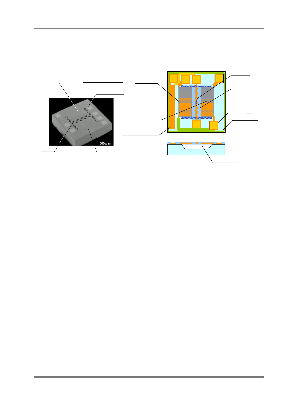
Thermopile B
Thermopile A
mass flow sensing method by using heat wire. It has a heater in the center of the chip, and the
upstream thermopile (A) and the downstream thermopile (B) are located on either side of the
heater, the base thermo-scope near the thermopile is made by a semiconductor process. The
cavity is formed at the bottom of the heater and the thermopile arrays, so then it is possible to
detect the heat from the heater effectively.
Heater
Upstream
Base thermoscope
Contact Pad
Upstream
Thermopile A
Downstream
Thermopile B
Base Thermo-scope
Thin film
Contact pad
Contact pad
Heater
Downstream
Cavity
Fig.3. Flow Sensor Chip Structure
5 D6F-series MEMS Flaw Sensor User’s Manual (A286)
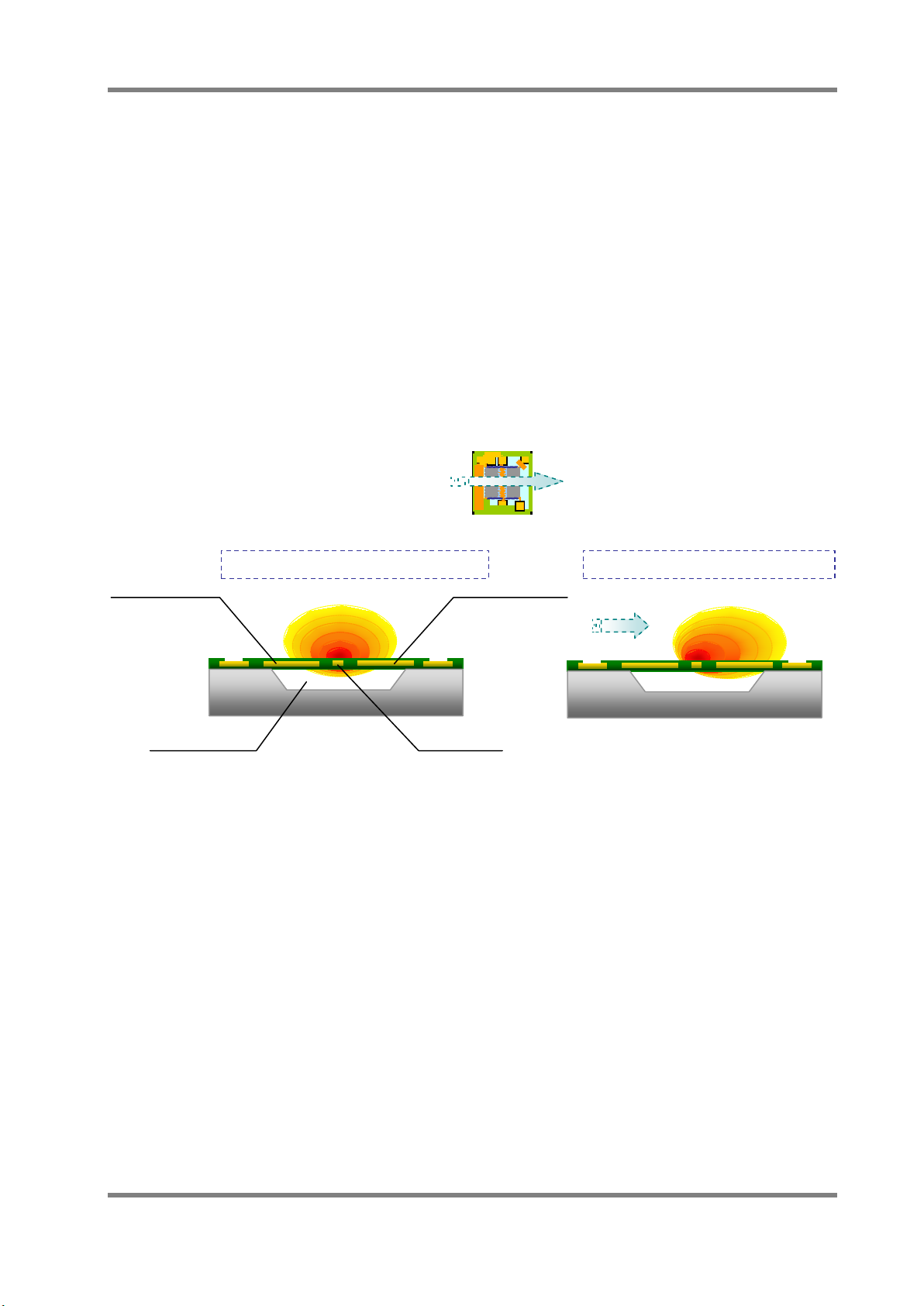
Heat distribution in no flow condition
The heat distribution is symmetric.
Heater
Cavity
Vd
Vu
Heat distribution in flow condition
4.2 Detecting principle of mass flow sensor
As shown in Fig.4, the constant current is flowing to the heater at the center of the chip and the
heater becomes hot. When there is no flow, the heat distribution around the heater is symmetric,
so Vu and Vd of the electromotive force from both thermopiles will be equal.
On the other hand, when there is a flow of gas on the sensor surface, the heat source is biased
on the downstream side according to the flow of gas. The electromotive force of the downstream
thermopile will be larger than the upstream thermopile (Vd > Vu). The output difference between
the two thermopiles is approximately proportional to the square root of the mass flow rate of the
gas through the sensor surface. The output sensitivity and the mass flow rate depend on the
composition ratio of the gas. Through amplification, it is possible to electronically detect the flow
rate of the gas. The flow velocity sensor is adjusted so that it can output a voltage that
corresponds to the flow velocity at the condition of 25℃, 101.3kPa from the mass flow rate.
When the flow direction is perpendicular to the thermopiles and heater.
Flow Direction
Upstream
Thermopile
Downstream
Thermopile
Vd=Vu
Vout = Voff +(Vd - Vu)× gain
Vout:Output voltage, Voff:Offset voltage
Vd-Vu ∝ √ (Flow rate)
Fig4. Sensing image of mass flow sensor using heat wire
Vd≠Vu (Vd > Vu)
The downstream temperature is high
compare to the upstream temperature.
D6F-series MEMS Flaw Sensor User’s Manual (A286) 6

Type
Type D6F-01A1-110
Type D6F-02A1-110
Application medium*2
Air
Port style
Bamboo Joint
Max Size:φ8.6mm , Min Size:φ7.4mm
Electrical connection
Connector (three wires)
Power supply voltage
DC10.8~26.4V
Current consumption
Max. 15mA, No load, Vcc=12~24V at 25℃
Accuracy
±3%F.S (at 25℃)
Repeatability*3
±0.3%F.S .
Min. output voltage
DC0V (Resistive load 10kΩ)
Absolute maximum supply voltage
DC26.4V
Case material
PPS
Protecting structure
IP40 (IEC standard)
Maximum permission pressure
200kPa
Pressure drop*3
0.42kPa
10.6kPa
Operating temperature
(with no ice or no dew condensation)
Operating humidity
35~85%RH (with no dew condensation)
Storage temperature
(with no ice or no dew condensation)
Storage humidity
35~85%RH (with no dew condensation)
Insulation resistance
Min. 20MΩ (DC500, between lead terminal and the base)
Withstanding voltage
AC500V 50/60Hz for one minute between the lead terminals
and the base (Leakage current is 1mA max.)
5 Product Features
・ Mass Flow Sensing
・ Wide Range Sensing Ability
・ Low Power Consumption
・ Ultra Small Size of MEMS Sensor
5.1 Characteristics of flow sensors
Table3. Representative Specifications Example of Mass Flow Sensor (D6F-□□A1-110)
Flow range*1 0~1 L/min 0~2 L/min
Output signal
Max. output voltage DC5.7V (Resistive load 10kΩ)
Absolute maximum output voltage DC6V
Temperature characteristics
DC1~5V (Non-linear output, Resistive load 10kΩ)
-10~+60℃
-40~+80℃
Within ±3%F.S. of detected characteristics of at 25℃
Over ambient temperature rang -10~+60℃
Weight 12.8g
*1. L/min (Normal) means the volumetric flow rate at 0degC, 101.3kPa. (1 atm)
*2. Use clean and dry gas without a dust and an oil mist.
*3. Reference Value (Typical value)
7 D6F-series MEMS Flaw Sensor User’s Manual (A286)
 Loading...