

Page 1
Touch Switch D5C 1
Limit
switches
Touch Switch
D5C
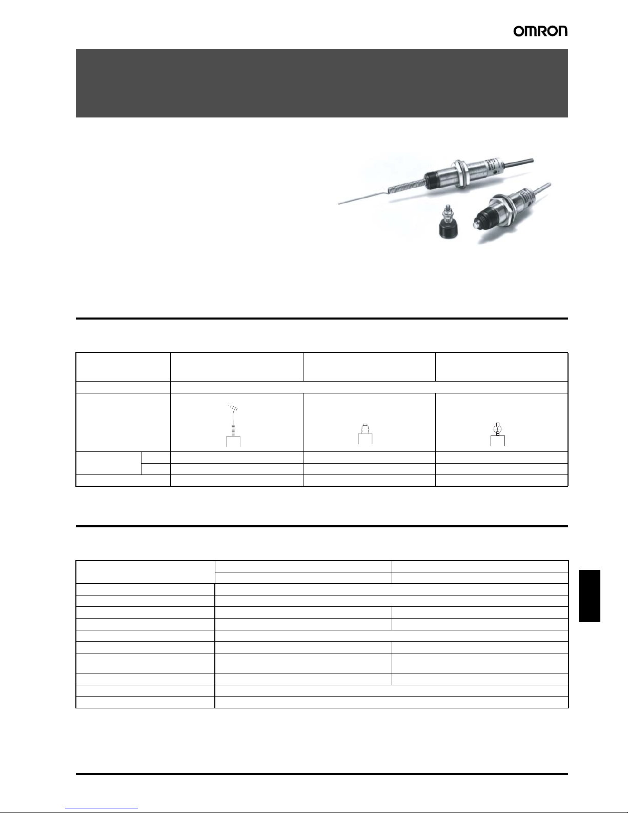
Unique 18 mm dia. Capacitive Touch Switch
with Choice of Three Actuators is Activated
with Only a Very Slight Physical Contact
• Lightweight objects, such as thin wire or foil can be accurately
detected.
• Solid-state switch activates the moment its actuator comes in
contact with the object.
• Amplifier, operation indicator, and sensitivity adjuster are builtin on all models.
• Conforms to IEC IP67 and NEMA Type 6, 6P.
• Actuators can be freely interchanged between switch units.
• A unique free-attachment version allows any kind of actuator
antenna to be attached.
Ordering Information
■ List of Models
Specifications
■ Characteristics
Features Usable by bending tip of antenna.
Overtravel of 20 mm max.
Ideal for high-accuracy position control.
Overtravel of 3.5 mm max.
Any actuator can be attached.
Cable 3 m
Actuator
Power source DC D5C-1DS0 D5C-1DP0 D5C-1DA0
AC D5C-1AS0 D5C-1AP0 D5C-1AA0
Antenna only D5C-00S0 D5C-00P0 D5C-00A0
Coil spring
Plunger
Free-attachment
Model DC AC
D5C-1D@0D5C-1A@0
Degree of protection Equivalent to IP67 (NEMA 6, 6P)
Durability Mechanical: 10,000,000 operations min. (at rated overtravel value)
Supply voltage (operating voltage) 12 to 24 VDC (10 to 30 VDC), (ripple: 10% max.) 100 to 240 VAC (45 to 264 VAC), 50/60 Hz
Rated frequency --- 50/60 Hz
Sensitivity setting range 30 to 100 pF
Current consumption 17 mA max. ---
Leakage current Circuit: ---
Antenna: 1 mA max.
Circuit: 2 mA max.
Antenna: 1 mA max.
Response time 2 ms max. 8 ms max.
Output current 200 mA max. (resistive load)
Insulation resistance 50 MΩ min. (at 500 VDC) between lead wires and case
Page 2
2 To uch Swit c h D5C
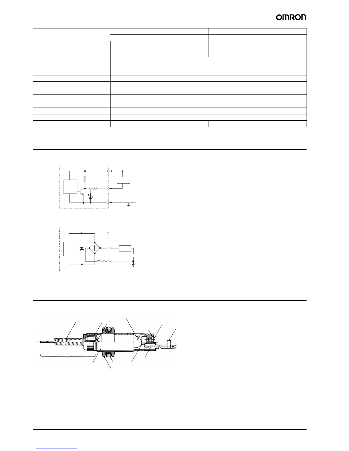
Output Circuit
Note: Color in ( ) denotes the old model.
Nomenclature
Dielectric strength 1,000 VAC, 50/60 Hz for 1 min between current-car-
rying metal parts and non-current-carrying metal
parts
2,000 VAC, 50/60 Hz for 1 min between current-carrying metal parts and non-current-carrying metal
parts
Rated insulation voltage (U
i
) 1,000 VAC
Pollution degree
(operating environment)
Level 3 (IEC947-5-1)
Protection against electric shock Class II
Proof tracking index (PTI) 175
Switch category D (IEC335)
Vibration resistance 10 to 55 Hz, 1.5-mm double amplitude
Shock resistance
1,000 m/s
2
min.
Ambient temperature Operating: –25°C to 70°C (with no icing)
Ambient humidity 95% max.
Weight Approx. 110 g (in case of D5C-1DSO) Approx. 120 g (in case of D5C-1ASO)
Model DC AC
D5C-1D@0D5C-1A@0
4.7 kΩ
2.2 Ω
D5C-1D@0 (DC Model)
D5C-1A@0 (AC Model)
Switch
main
circuit
Load
Brown
Black
Blue
12 to 24 VD
C
Switch
main
circuit
Load
Brown
Blue
100 to 240 VAC
(Red)
(White)
(Black)
(White)
(Black)
D5C-1DS0
Coil spring actuator
(Stainless steel)
Caution label
Contactor
LED operation
indicator
Sensitivity adjuster
O ring
Actuator
Case
Washer
Mounting nut
Lead wire
Filled with glass epoxy
O ring
Page 3

Touch Switch D5C 3
Limit
switches
Engineering Data
Typical Examples
0
50
100
150
200
−40 −25 0 40 70 80
0
50
100
150
200
−40 −25 0 40 70 80
D5C-1D@0 (24 VDC) D5C-1A@0 (100 VAC)
With sensitivity adjuster
set to minimum sensitivity
With sensitivity adjuster
set to maximum sensitivity
With sensitivity adjuster
set to minimum sensitivity
With sensitivity adjuster
set to maximum sensitivity
Temperature Characteristics of DC Models Temperature Characteristics of AC Models
Sensitivity (pF)
Te mperature (°C
)
Sensitivity (pF)
Te mperature (°C
)
200
150
100
50
0 100 200 30045
0
50
100
150
200
10 20 30
With sensitivity adjuster
set to minimum sensitivity
With sensitivity adjuster
set to maximum sensitivity
With sensitivity adjuster
set to maximum sensitivity
With sensitivity adjuster
set to minimum sensitivity
Voltage Characteristics of DC Model
D5C-1D@0 (at 25°C)
Voltage Characteristics of AC Model
D5C-1A@0 (at 25°C)
Sensitivity (pF)
Sensitivity (pF)
Vol tage (V
)
Vol tage (V
)
Page 4

4 To uch Swit c h D5C
Dimensions
Note: 1. All units are in millimeters unless otherwise indicated.
2. Unless otherwise specified, a tolerance of ±0.4 mm applies to all dimensions.
M18 x 1
44
14
37
28
56
61
(3,000)
(89)
M18 x 1
44
37
24
56
61
(3,000)
(85)
M18 x 1
4
414
51
37
56
101.5
61
(3,000)
(162.5)
D5C-1DS0
D5C-1DP0
D5C-1DA0
Two internal
lock washers
Lock nut
4 dia.
Two flat
washers
Self-locking
nut
M4 x 0.7
(see note 1)
(See note 2)
LED Operation
indicator
16.5 dia.
16.7 dia.
7.1
dia.
29 dia.
Two clamping nuts
(Width: 24; thickness: 4)
Caution label (see note 3)
Two internal lock washers
Overtravel
4 dia.
16.5
dia.
5
dia.
(See note 2)
LED Operation
indicator
(See note 1)
16.7 dia.
7.1
dia.
29 dia.
Two clamping nuts
(Width: 24; thickness: 4)
Caution label (see note 3)
LED Operation
indicator
Two clamping nuts
(Width: 24; thickness: 4)
Two internal lock washers
Overtravel
4 dia.
1.2 dia.
(see note 1)
(See note 2)
16.5 dia.
6.5
dia.
16.7 dia.
7.1
dia.
29 dia.
Caution label (see note 3)
DC Models
Coil Spring
Plunger
Free-attachment
Note: 1. The stainless steel wire actuator can move in any direction. However, limit the overtravel to within 20 mm from the free position. The force that
pushes the actuator must not exceed 1.96 N.
2. Vinyl insulated round cord (oil- and shock-resistant type)
4 dia., three cores × 0.2 mm
2
.
3. Use after removing the caution label.
Note: 1. The overtravel of the stainless steel plunger is within 3.5 mm. Do not apply a force greater than 9.8 N to the plunger.
2. Vinyl insulated round cord (oil- and shock-resistant type)
4 dia., three cores × 0.2 mm
2
.
3. Use after removing the caution label.
Note: 1. Limit the total length of actuator wire to 1 m or less. When mounting the Switch to a metal plate, do not exceed an area of 200 cm
2
.
2. Vinyl insulated round cord (oil- and shock-resistant type)
4 dia., three cores y 0.2 mm
2
.
3. Use after removing the caution label.
Page 5

Touch Switch D5C 5
Limit
switches
M18 x 1
44
14
52
28
71
76
(3,000)
(104)
M18 x 1
44
52
71
24
76
(3,000)
(101)
M18 x 1
44
14
51
52
71
101.5
76 (3,000)
(177.5)
D5C-1AS0
D5C-1AP0
D5C-1AA0
Two internal
lock washers
Lock nut
4 dia.
7.1 dia.
Two flat
washers
Self-locking
nut
M4 x 0.7
(see note 1)
(See note 2)
LED Operation
indicator
16.5 dia.
16.7 dia.
29 dia.
Two clamping nuts
(Width: 24; thickness: 4)
Caution label (see note 3)
Two internal
lock washers
Overtravel
4 dia.
7.1
dia.
16.7
dia.
16.5
dia.
5 dia.
(See note 2)(See note 1)
LED Operation
indicator
29 dia.
Two clamping nuts
(Width: 24; thickness: 4)
Caution label (see note 3)
LED Operation
indicator
Two internal
lock washers
Overtravel
4 dia.
6.5 dia.
1.2 dia.
(see
note 1)
(See note 2)
16.5 dia.
16.7 dia.
7.1
dia.
29 dia.
Two clamping nuts
(Width: 24; thickness: 4)
Caution label (see note 3)
AC Models
Coil Spring
Plunger
Free-attachment
Note: 1. The stainless steel wire actuator can move in any direction. However, limit the overtravel to within 20 mm from the free position. The force that
pushes the actuator must not exceed 1.96 N.
2. Vinyl insulated round cord (oil- and shock-resistant type)
4 dia., two cores × 0.3 mm
2
.
3. Use after removing the caution label.
Note: 1. The overtravel of the stainless steel plunger is within 3.5 mm. Do not apply a force greater than 9.8 N to the plunger.
2. Vinyl insulated round cord (oil- and shock-resistant type)
4 dia., two cores × 0.3 mm
2
.
3. Use after removing the caution label.
Note: 1. Limit the total length of actuator wire to 1 m or less. When mounting the Switch to a metal plate, do not exceed an area of 200 cm
2
.
2. Vinyl insulated round cord (oil- and shock-resistant type)
4 dia., two cores × 0.3 mm
2
.
3. Use after removin
g
the caution label.
Page 6

6 To uch Swit c h D5C
Application Examples
Precautions
Refer to the “Precautions for All Switches” in the separate Technical information about Basic Switches or Limit Switches.
Make sure that the antenna does not come into
contact with the human body, otherwise an electric
shock may be received.
■ Correct Use
Grounding of Antenna and Sensing
Object (Size of Sensing Object)
Grounded Object
If the sensing object is the following grounded conductor, its size will
not affect the operation of the D5C. Check for the presence of insulators sticking to the sensing object or the corrosion of the sensing
object, however, so that the ground resistance will not exceed 3 kΩ.
Non-grounded Object
If the sensing object is the following non-grounded conductor, the
D5C will operate if the capacitance between the sensing object and
the ground is 30 pF or more. The larger the surface area of the sensing object is, the higher its capacitance will be. The shorter the distance between the sensing object and the ground is, the higher the
capacitance will be. Furthermore, the capacitance greatly varies with
the ground condition (e.g., dry sand, concrete, or wet soil).
Conditions of Sensing Object
The detection of conductors (e.g., iron, stainless steel, aluminum,
and brass objects) poses no particular problem. A conductor coated
with paint cannot be detected, however, because there is no electrical continuity between the antenna and the conductor.
Non-conductive objects (e.g., plastic, ceramic, glass, and cloth
objects) can be detected by grounding them indirectly.
Antenna
Shape and Extension
If a metal plate is used as an antenna by connecting it to the built-in
or separated antenna of the D5C, the surface area of the metal plate
must be 200 cm
2
maximum (Fig. 1). The antenna can be extended,
provided that the total length of the antenna is 1 m maximum (Fig. 2)
and that the bottom of the antenna is at least 10 cm (Fig. 3) away
from the ground. Refer to the illustrations below.
The D5C may be damaged if the antenna is excessively large or
heavy or if the antenna is used in locations with excessive vibration
or shock. Be sure to check the locations before use.
D5C
D5C
D5C
1.0 mm
1.0 mm
D5C D5C
Wire
Steel plate
Press
Detection of Incorrectly Set Work Detection of Fine Wire or Thin Plate Detection of Loose Screws
CAUTION
.
R
D5C
Grounded
conductor
3 kΩ max.
R: 3 kΩ max.
The sensing object must not come into contact with
the human bod
y
.
Contact with Grounded Conductor
The sensing object is equivalently grounded through
ground resistor R.
.
D5C
C
Generally, the conductor will
be detectable if the ambient
humidity is 60% to 70% and
the surface area of the conductor is approximately 300
x 500 mm.
Nongrounded
conductor
30 pF min.
Contact with Non-grounded Conductor
The sensing object is equivalently grounded
through capacitor C.
C: 30 pF min.
Page 7

Touch Switch D5C 7
Limit
switches
Parallel Arrangement
If there are multiple D5Cs are located in parallel, make sure that the
distance between adjacent antennas is at least 3 cm.
Maintenance
Make sure that the portion of the antenna that comes into contact
with sensing objects is free of oil, dirt, or rust, or any other insulator.
Otherwise, the D5C will not operate.
The degree of protection of the D5C is IP67. The D5C cannot be,
however, used in the water or oil.
Locations with Sprayed Water or Oil
The D5C may malfunction in locations where the D5C is frequently
exposed to sprayed water or oil. Especially, the D5C may malfunction
more frequently if it is exposed to sprayed water-soluble cutting oil. In
such locations, be sure to take appropriate measures to protect the
D5C from oil and water.
Wiring and Connections
Be sure to wire the D5C correctly according to the color of each cord.
Incorrect wiring may damage the internal components of the D5C or
the D5C may malfunction.
If AC models are connected in parallel, make sure that a load is connected to each of the models.
A maximum of two models can be connected in series provided that
100 to 240 V is supplied. DC models cannot be connected in series.
Be sure to supply power to the D5C via the load. If power is supplied
to the D5C directly, the fuse will blow.
If there are wire power lines or high-tension lines close to the cord of
the D5C, be sure to wire the cord of the D5C away from power lines
or high-tension lines or lay the cord in an exclusive, shielded conduit.
Remove the caution label on the end of the cord before wiring the
cord.
D5C-1A@0 (AC Models)
Be aware that the D5C-1A@0 not in operation has a leakage current
of approximately 2 mA. Especially, if the load is a relay with a current
flow of 10 mA or less, a reset failure may result due to the residual
voltage. Therefore, connect a bleeder resistor as shown below so
that the residual voltage will be less than the reset voltage of the
load.
If a DC relay or DC counter is used as a load connected through an
electronic timer or current rectification circuit, pay the utmost attention so that the leakage current of the D5C AC model will not cause
the load to malfunction.
Sensitivity Adjustment
The sensitivity of the D5C can be adjusted by turning the adjuster on
the rear side with a flat-blade screwdriver.
The sensitivity increases by turning the adjuster clockwise and
decreases by turning the adjuster counterclockwise.
Be sure to turn the adjuster with a torque of 4.9 to 7.8 mN • m.
If excessive torque is applied, the adjuster will break.
D5C
D5CD5C
l
1
l
2
l
4
l6l
5
l
3
l1 + --- l6 ≤1 m
Metal plate
(200 cm
2
max.)
Fig. 1 Fig. 2
10 cm min.
1 m
max.
Fig. 3
Ground
D5C
D5C
D5C
D5C
Fig. 4
3 cm min.
3 cm min.
D5C
D5C
Load
100 to 240 VAC
D5C
Power
source
Incorrec
t
D5C
The bleeder resistance and permissible power are obtained
from the following formula.
R ≤ V
S
/(10 - I) (kΩ)
P > V
S
2
/
R
(mW)
P: W number of bleeder load
P: Withstanding power of bleeder resistor
(Practically, the wattage must be a few times larger than the
obtainable value.)
Load
Bleeder resistor R
AC power
supply Vs
I: Load current (mA)
− +
Set point
SENSI
Page 8

8 To uch Swit c h D5C
Grounding
In order to maintain the operational reliability of the D5C, be sure to
ground the blue or black wire of the power cord.
The service power supply of the PC (Programmable Controller) is not
available to the D5C-1D@0. The negative line of the service power
supply of the PC is not grounded. Therefore, the D5C may not operate.
Furthermore, if the negative line of the service power supply is
grounded, the noise resistance of the PC will drop.
Provided that single-phase 200 V is supplied to the D5C-1A@0, if
one phase is grounded, the power supply will be short-circuited and
a machinery breakdown will result. Use an isolating transformer and
ground the secondary side of the transformer instead.
In the above case, be sure to ground the secondary side, otherwise
the D5C may not operate.
Mounting
Do not tighten the nuts with excessive force. The maximum permissible tightening force of each nut with a washer is 29.4 N • m.
Others
Do not disassemble the D5C, otherwise the internal wiring will be
damaged and the D5C will fail to operate.
The sealing of the D5C uses nitrile butadien rubber (NBR), which is
highly oil resistive. If exposed to some types of oil or chemical
indoors or outdoors, however, the NBR may deteriorate. Contact your
OMRON representative for details.
When mounting the antenna to the D5C, be sure to tighten the
antenna to a torque of 0.39 to 0.83 N·m. If the antenna is not tightened securely, the built-in contact may break.
If an appropriate antenna is mounted to a free attachment model,
hold the nut on the outer side with a wrench so that the nut will not
move. Then tighten the nut on the inner side within a torque range of
0.78 and 1.18 N·m.
In the interest of product improvement, specifications are subject to change without notice.
ALL DIMENSIONS SHOWN ARE IN MILLIMETERS.
To convert millimeters into inches, multiply by 0.03937. To convert grams into ounces, multiply by 0.03527.
Cat. No. C061-E2-04
D5C
AC
Load
Brown
Blue
(Black)
The lead wire colors of the D5C have been changed in
compliance with the latest applicable JIS standards. Colors in
p
arentheses are previous ones.
(White)
18.5
+0.5
−0
dia.
Mounting Hole Dimension
Wrench
Direction of turn
Antenna
 Loading...