

Page 1
265
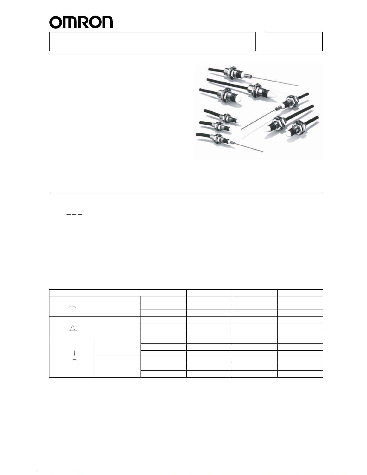
D5B Mechanical Touch Switch
Detects Objects in Multiple Directions
with High Sensitivity, Ideal for Robotics
■ Detects object contact from multiple directions
and operates even with a slight force.
■ Slow-action switching mechanism used. Move-
ment differential as small as 0.01 mm assures
high accuracy of detection.
■ Gold-plated contact with coil spring capable of
switching micro current/voltage l oad while provid ing high contact reliability.
■ Highly resistant to dust, fine particles and water or
oil splash, conforming to IP67.
■ Three sizes (M10, M8, and M5) and three types of
actuators (hemispheric, cone-shaped, and wobble
stick).
Ordering Information
■ Model Number Legend
■ List of Models
Type Cable length M5 M8 M10
1 m D5B-5011 D5B-8011 D5B-1011
3 m D5B-5013 D5B-8013 D5B-1013
5 m D5B-5015 D5B-8015 D5B-1015
1 m D5B-5021 D5B-8021 D5B-1021
3 m D5B-5023 D5B-8023 D5B-1023
5 m D5B-5025 D5B-8025 D5B-1025
Short spring 1 m D5B-5511 D5B-8511 D5B-1511
3 m D5B-5513 D5B-8513 D5B-1513
5 m D5B-5515 D5B-8515 D5B-1515
Long spring 1 m --- --- D5B-1531
3 m --- --- D5B-1533
5 m --- --- D5B-1535
D5B-@@@
1 2 3
1. Size
5: M5
8: M8
1: M10
2. Actuator
01: Hemispheric
02: Cone-shaped
51: Wobble stick (short spring)
53: Wobble stick (lon
g
spring). Only with the M10 type.
3. Cable length
1: 1 m
3: 3 m
5: 5 m
Hemispheric actuator
Cone-shaped actuator
Wobble stick
actuator
Page 2
266
D5BD5B
Specifications
■ Ratings
■ Characteristics
Note: 1. The above figures are initial values.
2. Life expectancy values are calculated at an operating temperature of 5
°C to 35°C, and an operating humidity of 40% to 70%.
Contact your OMRON sales representative for more detailed information on other operating environments.
3. 16.7 Hz, 1.5-mm double amplitude for wobble stick models.
4. 50 m/s
2
min. for wobble stick models.
5. Excluding the wobble stick models.
Switching power 1 mA at 5 VDC to 30 mA at 30 VDC (resistive load)
Degree of protection IP67
Life expectancy (see note 2) Mechanical: 10,000,000 operations min.
Electrical: 5,000,000 operations min. (at 30 VDC, 30-mA resistive load)
Operating speed 5 to 500 mm/s
Operating frequency Mechanical: 120 operations/min.
Electrical: 60 operations/min.
Insulation resistance 100 M
Ω min. at 250 VDC between each terminal and ground
Contact resistance With 1 m cable: 700 m
Ω max. (initial value)
With 3 m cable: 1.9
Ω max. (initial value)
With 5 m cable: 3.1
Ω max. (initial value)
Dielectric strength 250 VAC, 50/60 Hz for 1 min between terminals of same polarity (TTP)
1,000 VAC, 50/60 Hz for 1 min between current-carrying metal parts and ground
(600 VAC for M5 model)
Vibration resistance Malfunction: 10 to 55 Hz, 1.5-mm double amplitude (see note 3)
Shock resistance
Mechanical: 1,000 m/s
2
min.
Malfunction: 300 m/s
2
min. (see note 4)
Ambient temperature Operating: –10
°C to 70°C (with no icing)
Ambient humidity Operating: 95% max.
Actuator strength 14.7 N {1.5 kgf} (see note 5)
Weight Switch:
M5: approx. 14 g, M8: approx. 20 g, M10: approx. 21 g
Cable: approx. 10 g/m
Page 3

267
D5BD5B
■ Operating Characteristics
Note: 1. The operating characteristic values shown in the abov e table are measured at the portions indicated by the downward arrows
in Dimensions.
2. The operating principle of the Mechanical Touch Switch is similar to that of the ordinary switch in that the Mechanical Touch
Switch has a switch inside the housing operated by the movement of the actuator which in turn is moved by the force applied to
it. Mechanical Touch Switches differ from ordinary switches mostly in areas of operating direction flexibility, sensitivity and size.
Engineering Data
TT (max.)
(reference value)
OF (max.) Permissible
operating force
(max.)
PT
(reference value)
X, Y Z X, Y Z X, Y, Z X, Y Z
M5 1.0 mm 0.8 mm 0.49 N {50 gf} 0.74 N {75 gf} 1.96 N {200 gf} 0.6 mm 0.3 mm
M8 1.2 mm 0.9 mm 0.74 N {75 gf} 0.98 N {100 gf} 0.6 mm 0.3 mm
M10 1.3 mm 1.0 mm 0.98 N {100 gf} 1.47 N {150 gf} 0.7 mm 0.3 mm
M5 2.2 mm 0.8 mm 0.20 N {20 gf} 0.74 N {75 gf} 1.96 N {200 gf} 0.6 mm 0.3 mm
M8 3.0 mm 0.9 mm 0.20 N {20 gf} 0.98 N {100 gf} 1.4 mm 0.3 mm
M10 4.0 mm 1.0 mm 0.39 N {40 gf} 1.47 N {150 gf} 2.0 mm 0.3 mm
M5 22 mm --- 0.05 N {5 gf} max. --- 0.49 N {50 gf} 11 mm ---
M8 23 mm 11 mm ---
M10 30 mm 14 mm ---
Hemispheric
actuator
XY
Z
Cone-shaped
actuator
X
Y
Z
Wobble stick
actuator
X
Y
Electrical Life Expectancy (cosφ = 1)
Operating temperature: 5°C to 30°C
Operating humidity: 40% to 70%.
Life expectancy (x 10 operations)
6
Switching current (mA)
30 VDC
Page 4

268
D5BD5B
Nomenclature
Note: NBR rubber is used with this Switch.
Operation
■ Contact Form
Dimensions
Note: 1. All units are in millimeters unless otherwise indicated.
2. Unless otherwise specified, a tolerance of
±0.4 mm applies to all dimensions. Values in parentheses () are cumulative values
and may exceed tolerance of
±0.4 mm.
3. The square @ in the models represents the cable length. Refer to Order ing Information.
M5 Type
Actuator
Axis
Rubber boot
Plunger
Reset spring
Case
Reset spring
Base
Resin
Mounting nut
Cable
Brown
Blue
(Normally closed contact)
M5 × 0.5
(see note 2)
S-FLEX V-HKCVV
equal level, 3 dia.
0.08 mm
2
T wo cores
Clamping nut
Toothed lock washer
0.4
dia.
2.3
dia.
4.2
dia.
8
(9.2)
Stainless steel wire
5
(See note 1)
2
6.9±2
41.9±2
5.9
16.2
(64.1)
2.5
M5 × 0.5
(see note 2)
S-FLEX V-HKCVV
equal level, 3 dia.
0.08 mm
2
T wo cores
Clamping nut
Toothed lock washer
4.3 dia.
0.5R
8
(9.2)
Resin
plunger
1
2.5
(See
note 1)
4.9 5.9
16.2
(27)
M5 × 0.5
(see note 2)
S-FLEX V-HKCVV
equal level, 3 dia.
0.08 mm
2
T wo cores
Clamping nut
Toothed lock washer
2.15R
(See
note 1)
Resin plunger
2.4 5.9
16.2
(24.5)
4.3 dia.
2.15 2.5
8
(9.2)
Hemispheric Plunger
D5B-501@
Cone-shaped Plunger
D5B-502@
Wobble Stick
D5B-551@
Note: 1. Operating characteristics (X, Y) measuring position
2. The threads of the case are not standard; 0.5-mm pitch. There
fore standard tapping to the case is not possible for mounting.
Page 5

269
D5BD5B
M8 Type
M10 Type
M8 × 0.5
(see note 2)
S-FLEX V-HKCVV
equal level, 3 dia.
0.08 mm
2
T wo cores
Clamping nut
Toothed lock washer
7 dia.
0.8R
13
(15)
(See
note 1)
8.5 7.3
16.7
(32.5)
1
2.5
Resin
plunger
M8 × 0.5
(see note 2)
S-FLEX V-HKCVV
equal level, 3 dia.
0.08 mm
2
T wo cores
Clamping nut
Toothed lock washer
7 dia.
3.5R
13
(15)
Resin
plunger
3.5
2.5
(See
note
1)
4
7.3
16.7
(28)
Hemispheric Plunger
D5B-801@
Cone-shaped Plunger
D5B-802@
(Rising part of the ball)
M8 × 0.5
(see note 2)
S-FLEX V-HKCVV
equal level, 3 dia.
0.08 mm
2
T wo cores
Clamping nut
Toothed lock washer
0.6
dia.
3.9
dia.
7
dia.
13
(15)
(92.8)
68.8±2
7.3
16.7
5
3
11.8±2
2.5
(See note 1)
Stainless
steel wire
Wobble Stick
D5B-851@
Note: 1. Operating characteristics (X, Y) measuring position
2. The threads of the case are not standard. Therefore standard
tapping to the case is not possible for mounting.
M10 × 0.5
(see note 2)
S-FLEX V-HKCVV
equal level, 3 dia.
0.08 mm
2
T wo cores
Clamping nut
Toothed lock washer
9
dia.
4.6
dia.
0.6
dia.
13
15
18 dia.
(See note 1)
5
5
13.3
2.5
83.3
20.5
7.3
(111.1)
Resin
plunger
M10 × 0.5
(see note 2)
S-FLEX V-HKCVV
equal level, 3 dia.
0.08 mm
2
T wo cores
Clamping nut
Toothed lock washer
9 dia.
0.9R
13
15
18 dia.
1
2.5
(See
note 1)
11.5 20.5
(39.3)
7.3
Stainless
steel wire
M10 × 0.5
(see note 2)
S-FLEX V-HKCVV
equal level, 3 dia.
0.08 mm
2
T wo cores
Clamping nut
Toothed lock washer
9 dia.
4.5R
13
15
18 dia.
4.5
2.5
5.5
20.5
(33.3)
7.3
Resin
plunger
Hemispheric Plunger
D5B-101@
Cone-shaped Plunger
D5B-102@
Wobble Stick
D5B-151@
(see note 1)
(Rising part of the ball)
Page 6

270
D5BD5B
Precautions
■ Correct Use
Do not impose a load exceeding 29.42 N on the cord, otherwise
the cord may break. If the cord is to be bent repeatedly, make
sure that the bending radius is at least 20 mm.
Mounting
Do not tighten the nuts with excessive torque. Refer to the following for the appropriate tightening torque and mounting dimensions of each nut.
The base incorporates special threads that cannot be mounted to
plates with standard tap holes.
An excessive load may deform the base. When mounting the
base, be careful not to impose an excessive load on the base.
Operation
Do not impose excessive force on the actuator. Even though the
actuator withstands a maximum force of 14.7N, if the D5B is
repeatedly actuated, make sure that the maximum force imposed
on the actuator is 1.96 N. If the actuator is, however, a wire spring
type, the maximum force imposed must be 0.49 N instead.
The operating characteristics of the D5B vary with the direction
(i.e., X, Y, or Z) in which force is imposed. Refer to page 267.
The wobble stick model is actuated when force is imposed on the
tip of the wobble stick and the built-in switch unit is closed or
opened. This is different from the NL Limit Touch Switch or D5C
Column Touch Switch in terms of the main mechanism. The NL or
D5C is actuated when the actuator comes into contact with an
actuating object.
The wobble stick model may break if the stroke is excessive.
Make sure that the total travel (TT) is within the reference value
provided in the datasheet.
Attach an appropriate cover for protecting the D5B from direct
exposure to sprayed oil or water. No protective cover is, however,
provided together with the D5B.
The D5B may be damaged by ozone and failures may result if the
D5B is used outdoors. Consult your OMRON representative
before attempting to use the D5B outdoors.
Outdoor environmental conditions may have a bad influence on
the service life of the D5B. Refer to the general precautions of
Limit Switches for details.
M10 × 0.5
(see note 2)
S-FLEX
V-HKCVV equal
level, 3 dia.
0.08 mm
2
Two cores
Clamping nut
Toothed lock washer
9
dia.
4.6
dia.
0.6
dia.
13
18 dia.
(See note 1)
55
33.3
83.3
20.5
7.3
(111.1)
2.5
Stainless
steel wire
D5B-153@
Note: 1. Operating characteristics (X, Y) measuring position
2. The threads of the case are not standard. Therefore standard
tapping to the case is not possible for mounting.
15
Size Max. tightening
torque
Mounting hole
dimension
M5 0.98 N • m
M8 2.94 N • m
M10 3.92 N • m
5 dia.
+3
/
0
hole
8 dia.
+3
/
0
hole
10 dia.
+3
/
0
hole
ALL DIMENSIONS SHOWN ARE IN MILLIMETERS.
To convert millimeters into inches, multiply by 0.03937. To convert grams into ounces, multiply by 0.03527.
Cat. No. C060-E1-5
 Loading...