

Page 1
271
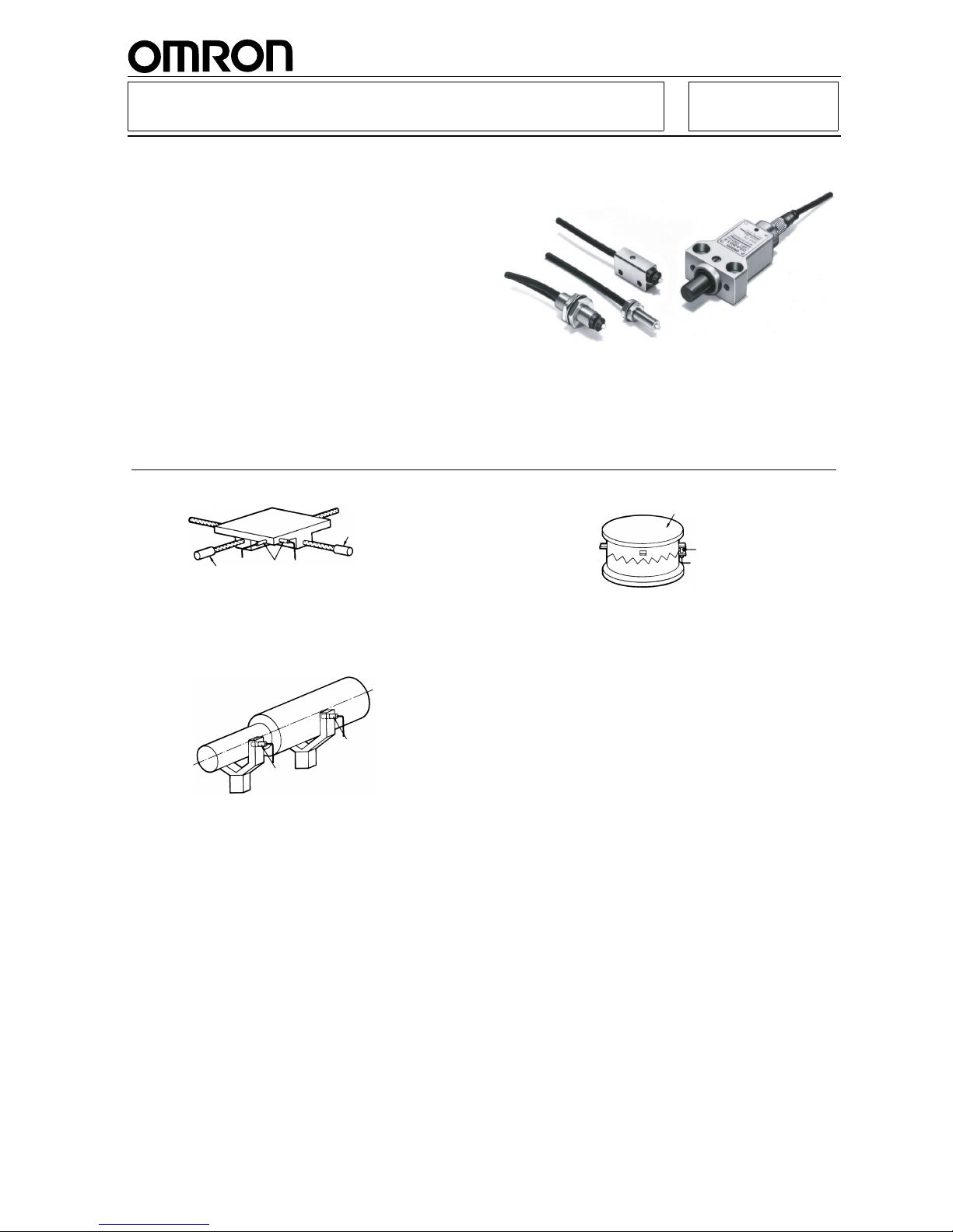
D5A High-precision Switch
High-precision Switch for Detecting
Micron-unit Displacement
■ Ideal for detecting and measur ing wear of cutti ng
tools or for original point of work.
■ Direct input possible to micropr ocessors and pro-
grammable controllers.
■ Types available with built-in operation indicator for
ease of operation monitor ing as well as a version
with fiber optics remote operation indicator.
■ A version with screw-type cable con nector avail-
able for easy installation and maintenance.
Application Examples
Origin Position Control of an X-Y Table
Coaxiality Inspection
Checking Turret Indexing Position
Note: Origin can be set to a desired position and the origin
position can be controlled using the D5A.
D5A
Motor
Motor
Note: The D5A can be mounted on a jig used for checking
deviation to inspect its coaxiality.
D5A
D5A
Note: Set the D5A on the turret indexing position to check if
the turret is engaged properly at the specified position.
D5A
Turret
Page 2
272
D5AD5A
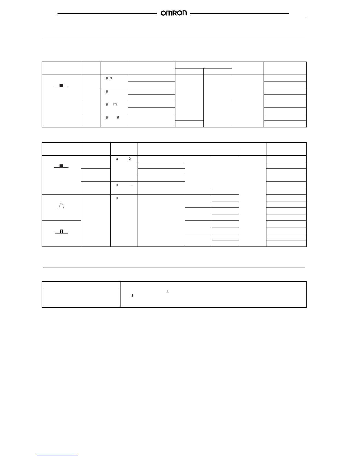
Ordering Information
■ List of Models
Contact Output Models (Without Operation Indicator)
Solid-state Output Models (With Operation Indicator)
Specifications
■ Ratings
Actuator Type Repeat
accuracy
Operating force Cable lead outlet Degree of
protection
Model
Type Length
Pin plunger M5 1
m
m max. 0.29 N max. Pre-wired 1 m IP40 D5A-1100
0.49 N max. D5A-1200
3
m
m max. 0.29 N max. D5A-2100
0.49 N max. D5A-2200
M8 1
m
m max. 0.49 N max. IP67 D5A-3200
0.98 N max. D5A-3300
M16 3
m
m max. 2.45 N max. D5A-7400
Connector D5A-7403
Actuator Type Repeat
accuracy
Operating force Cable lead outlet Degree of
protection
Model
Type Length
Pin plunger M8 1
m
m max.
0.49 N max. Pre-wired 1 m IP67 D5A-3210
0.98 N max. D5A-3310
Slim 0.49 N max. D5A-5210
0.98 N max. D5A-5310
M16 3
m
m max. 2.45 N max. D5A-7410
Connector D5A-7413
Top plunger
Limit 3
m
m max.
3.92 N max. Pre-wired 3 m D5A-8511
5 m D5A-8512
Connector 3 m D5A-8514
5 m D5A-8515
Bevel plunger
Pre-wired 3 m D5A-9511
5 m D5A-9512
Connector 3 m D5A-9514
5 m D5A-9515
Contact output models 10 mA at 24 VAC, 10 mA at 12 VDC
Solid-state output models 100 mA at 5 to 24 VDC
10%
Leakage current: 0.15 mA max.
Residual voltage: 3 V max.
Power consumption: 3 mW max.
Page 3

273
D5AD5A
■ Characteristics
Note: 1. The above figures are initial values.
2. Contact your OMRON sales representative for measurement conditions of the repeat accuracy.
3. Life expectancy values are calculated at an operating temperature of 5
C to 35C, and an operating humidity of 40% to 70%.
Contact your OMRON sales representative for more detailed information on other operating environments.
4. The value indicates the operating position change rate for a change of 1
C in the ambient temperature.
■ Operating Characteristics
Note: 1. The operating position of these types is the same as the free position because of high sensitivity (repeat accuracy: 1 mm max.).
2. Total movement is 1.9 to 2.1 mm. Set the appropriate stroke (plunging depth) to 1.0 to 1.5 mm from the FP.
Degree of protection D5A-1
#
, D5A-2#: IP40
Other than the above models: IP67
Repeat accuracy (see note 2) M5 (D5A-1
###
series), M8, slim type:1 mm max.
M5 (D5A-2
###
series), M16, limit type:3 mm max.
Life expectancy (see note 3) Mechanical: 10,000,000 operations min.
Malfunction: 1,000,000 operations min. (under rated load)
Deviation in electrical life expectancy after 1,000,000 operations
M5, M8, M16, slim type: 10
m
m max.
Limit type : 20
m
m max.
Operating speed 1
m
m to 0.5 m/s
Rated frequency 50/60 Hz
Insulation resistance 100 M
W
min. (at 250 VDC) between each terminal and ground
Contact resistance 800 m
W
max. (initial) with 1 m cable,
2.4
W
max. (initial) with 3 m cable, 4 W max. (initial) with 5 m cable)
Dielectric strength 1,000 VAC, 50/60 Hz for 1 min between each terminal and ground
Vibration resistance Malfunction: 10 to 55 Hz, 1.5-mm double amplitude
Shock resistance
Mechanical: 1,000 m/s
2
min.
Malfunction: 300 m/s
2
min.
Temperature coefficient
(see note 4)
M5, M8, slim type:
20 x 10–6/C max.
M16 type:
40 x 10–6/C max.
Limit type :
50 x 10–6/C max.
Ambient temperature Operating: –20
C to 75C (with no icing)
Ambient humidity Operating: 30% to 85% (30% to 95% with the seal rubber)
Model D5A-1100
D5A-2100
(see note 2)
D5A-1200
D5A-2200
(see note 2)
D5A-3200
D5A-3210
(see note 2)
D5A-3300
D5A-3310
(see note 2)
D5A-5210
(see note 2)
D5A-5310
(see note 2)
OF max. 0.29 N 0.49 N 0.49 N 0.98 N 0.49 N 0.98 N
OT min. 1.5 mm 1.5 mm 1.5 mm 1.5 mm 1.5 mm 1.5 mm
MD max. 5
m
m5
m
m5
m
m5
m
m5
m
m5
m
m
OP
(see note 1)
(2 mm) (2 mm) (6.5 mm) (6.5 mm) 10.5
0.4 mm 10.50.4 mm
Model D5A-7400/-7410
D5A-7403/-7413
D5A-8511/-8514
D5A-8512/-8515
D5A-9511/-9514
D5A-9512/-9515
OF max. 2.45 N 3.93 N
PT max. 1 mm 1 mm
OT min. 2 mm 5 mm 4 mm
MD max. 5
m
m5
m
m5
m
m
OP (4.4 mm) 21.0
0.4 mm 15.20.4 mm
FP (5 mm) (21.8 mm) (15.8 mm)
Page 4

274
D5AD5A
Engineering Data
Repeat Accuracy Examples (Reference Data)
Operation
■ Contact Form/Output Circuit Diagram
Contact Output Models Solid-state Output Models
(PNP Transistor Output)
0 50 100 150 200
+1
0
-1
-2
+2
1.4 µm
OP
RP
1.2 µm
0 50 100 150 200
+1
0
-1
-2
+2
(µm)
0.5 µm
0.6 µm
OP
RP
0 50 100 150 200
+1
0
-1
-2
+2
(µm)
1.1 µm
1.2 mm
OP
RP
0 50 100 150 200
+1
0
-1
-2
+2
(µm)
0.6 µm
OP
RP
0.6 µm
0 50 100 150 200
+1
0
-1
-2
+2
(µm)
OP
RP
1.2 µm
1.2 µm
+1
0
-1
-2
0 50 100 150 200
+2
(µm)
0.5 µm
0.6 µm
OP
RP
M5 Type (Contact Output) With
Repeat Accuracy of 1 µm max.
D5A-1@@@ Series
M5 Type (Contact Output) With
Repeat Accuracy of 3 µm max.
D5A-2@@@ Series
M8 Type (Contact/Solid-state Output)
With Repeat Accuracy of 1 µm max.
D5A-3@@@ Series
M16 Type (Contact/Solid-state Output)
With Repeat Accuracy of 3 µm max.
D5A-7@@@ Series
Slim Type (Solid-state Output) With
Repeat Accuracy of 1 µm max.
D5A-5@@@ Series
Limit Type (Solid-state Output) With
Repeat Accuracy of 3 µm max.
D5A-8@@@ Series, D5A-9@@@ Series
Number of repeated measurements Number of repeated measurements
Number of repeated measurements Number of repeated measurements
Number of repeated measurements Number of repeated measurements
Note: 1. HIC (hybrid integrated circuit)
2. An LED current limit resistor is incorporated.
3. The ZD absorbs surge.
4. The load can be connected to either the +V side
or 0V side.
820 Ω
270
kΩ
LED
Brown (White)
Load
Blue (Black)
HIC
+ V
0 V
ZD
Page 5

275
D5AD5A
Dimensions
Note: 1. All units are in millimeters unless otherwise indicated.
2. Unless otherwise specified, a tolerance of
0.4 mm applies to all dimensions.
S-FLEX V-HKCVV equal level,
3 dia. Two cores
0.08 mm
2
1M
2 dia.
Operation indicator (LED)
Two , 2 . 7
+0.1
-0
dia.
8
12
4
5
4.85R
Ceramic
plunger
Seal
rubber
OP (FP)
4
12±0.2
20
3 dia.
M8 × 0.5 (see note)
S-FLEX V-HKCVV equal level,
3 dia. Two cores
0.08 mm
2
1M
Two clamping nuts
Toothed lock washer
2 dia.
15 dia.
13
4.85R
OP (FP)
Ceramic
plunger
Seal
rubber
16.5
0.8
2.5
3 dia.
M8 × 0.5
(see note)
S-FLEX V-HKCVV equal level,
3 dia. Two cores
0.08 mm
2
1M
Two clamping nutsToothed lock washer
2 dia.
15 dia.
Operation indicator fiber, 2 dia.
(approx. 450 mm)
13
OP (FP)
4.85R
Ceramic plunger
Seal
rubber
0.8
2.5
3 dia.
21.5
M5 × 0.5
(see note)
S-FLEX V-HKCVV
equal level, 3 dia.
Two cores
0.08 mm
2
1M
Two clamping nuts
Toothed lock washer
1.3 dia.
10 dia.
8
3.7R
Ceramic plunger
OP (FP)
0.6
2.5
3 dia.
18
M5 Type
(Contact Output)
D5A-1100, D5A-2100
D5A-1200, D5A-2200
Slim Type
(Solid-state Output)
D5A-5210, D5A-5310
M8 Type
(Solid-state Output)
D5A-3210, D5A-3310
M8 Type
(Contact Output)
D5A-3200, D5A-3300
Note: The threads of the case are not
standard. Therefore, standard
tapping to the case is not possible
for mounting.
Note: The threads of the case are not
standard. Therefore, standard
tapping to the case is not possible
for mounting.
Note: The threads of the case are not
standard. Therefore, standard
tapping to the case is not possible
for mounting.
Page 6

276
D5AD5A
20
Two, M3 × 0.5
S-FLEX V-HKCVV equal level,
3 dia. Two cores
0.08 mm
2
3M/5M
Operation indicator (LED)
Two, 4.2 dia. holes
8 dia. spot facing depth: 5
20±0.2
16
20
±0.2
15
dia.
8
dia.
Nameplate
PT
OP
36
10
5
37.5
45
3
dia.
20
20
Two, M3 × 0.5
S-FLEX V-HKCVV
equal level, 3 dia.
Two cores
0.08 mm
2
3M/5M
8 dia.
Operation indicator (LED)
Two, 4.2 dia. holes
8 dia. spot facing depth: 5
Nameplate
6
3
OP
PT
30
20±0.2
16
20±0.2
15
dia.
10
5
37.5
45
3 dia.
20
20
M16 × 0.5
(see note)
S-FLEX V-HKCVV
equal level, 3 dia.
Two cores
0.08 mm
2
1M
Two clamping nuts Toothed lock washer
8 dia.
26 dia.
Operation indicator
(LED) (see note)
24
1/8-inch ultrahard ball
1.2
4
PT
OP
37.5
45
3 dia.
Nameplate
M16 Type
(Contact Output/Solid-state Output)
D5A-7400, D5A-7410
Limit Type
(Solid-state Output)
D5A-8511, D5A-8512
M16 Type
(Contact Output/Solid-state Output)
D5A-7403, D5A-7413
(Connector type)
Limit Type
(Solid-state Output)
D5A-8514, D5A-8515
(Connector type)
Limit Type
(Solid-state Output)
D5A-9511, D5A-9512
Limit Type
(Solid-state Output)
D5A-9514, D5A-9515
(Connector type)
Note: The dimensions are the
same as the above model's.
Note: Not available in the
contact output type.
Note: The dimensions are the
same as the above model's.
Note: The dimensions are the
same as the above model's.
(Length: 28.5)
30
Page 7

277
D5AD5A
Precautions
■ Correct Use
Handling of Fiber Cable
Do not pull or impose any force exceeding 29.42 N on the fiber
cable.
Make sure that the bending radius of the fiber cable is as large as
possible and at least 25 mm.
The 40-mm portion of the fiber cable on the connector end as
shown below must not be bent.
Do not impose compressing loads on the fiber cable.
The fiber cable can be cut with OMRON’s E39-F4 Cutting Tool.
Do not impose any force exceeding 29.42 N on the cord, other-
wise the cord may break. Make sure that the bending radius of
the cord is at least 20 mm.
Mounting
For the mounting dimensions, refer to the following figures and tables.
Do not tighten the nut with too much force.
Be sure to apply the clamping torque shown in this table.
When mounting the Switch to a panel, be sure to use the t oothed
lock washer attache as an accessory (to M5, M8, and M16 types
only). Use the washer on the panel surface opposite the object to
be detected by the Switch.
40 mm min.
R25 mm min.
Fiber cable
Dimensions M5 M8 M16
Contact
output
Solid-state
output
A Mounting hole 5.2
0.1 mm dia. 8.20.1 mm dia. 16.20.1 mm dia.
B Panel thickness 3 to 10 mm 5 to 8 mm 5 to 13 mm 10 to 17 mm
C Toothed lock washer 10 mm dia. 15 mm dia. 26 mm dia.
Dimensions Slim Limit
A Mounting pitch 12
0.2 mm 200.2 mm
BTapping M2.6 M4
Mounting hole
B
CA
A
B
2.8 mm dia.
+0.2°
−0°
4.2 mm dia.
+0.2°
−0°
Type Clamping torque
M5 0.98 N • m max.
M8 2.94 N • m max.
M16 9.81 N • m max.
Slim 0.29 N • m max. (M2.6 screw)
Limit 1.47 N • m max. (M4 screw)
Object
to be
detected
Panel
Nut
Toothed lock washer
Page 8

278
D5AD5A
Connection of Contact Output
Connection of Solid-state Output
Be sure to connect the load to the power source in series.
The operating state of the Switch can be checked by the LED
operation indicator (illuminants when the Switch is in operation)
incorporated in the solid-state output circuit.
The output residual voltage is approximately 3 V. Therefore, exercise care when selecting the load and setting the supply voltage.
The residual voltage, however, can be easily calculated because
it is almost constant and is free from the influence of fluctuation in
the load current.
Example:
1. In the above circuit, suppose the MY relay rated at 12 VDC
is used as the load. Since the must operate voltage of the
relay is 80% or less than the rated voltage, it is 12 x 0.8 =
9.6 V . The supply voltage, in turn, is 3 + 9.6 = 12.6 V.
Therefore, the relay may not operate with a 12 V power
source.
2. However, if the relay rated at 24 VDC is employed, the must
operate voltage and supply voltage of the relay are respectively 19.2 V and 22.2 V. The relay therefore can operate
with a 24 V power source.
When a solid-state circuit is turned OFF, leakage current of 0.15
mA (max.) flows, causing some voltages to remain in the load.
For this reason, be sure to check the must release voltage of the
load before using it.
Series Connection of Switches
The Solid-state Output-type Switches must not be connec ted in
series. To obtain the same effect as a series connection, form an
AND gate with a relay inserted between the Switch and load.
Parallel Connection of Switches
In principle, two or more D5A’s should not be used in an OR configuration.
However, they can be connected in parallel provided that both
switches A and B in the above figure do not operate at the same
time and that the load does not have to be kept energized. In this
circuit, however, the leakage current is increased, multiplied by
the number of Switches connected in parallel. Consequently, the
Switch may not release properly . To keep the load energized, connect a relay to each of the Switches as shown below.
Connection to Power Source
Be sure to connect the Switch to the power source via the load. If
directly connected to the power source, the internal elements of
the Switch may be damaged.
Correctly connect the white and black lead wires to the positive
and negative sides, respectively, of the power source. Although
the D5A will not be damaged even if the polarity is reversed by
mistake, if this happens, the Switch maintains the ON state (i.e.,
the contact is kept open) regardless of the presence or absence
of the object to be detected.
Others
Adjust the mounting of the D5A until the stroke of the pin plunger
is aligned with the stroke of the operating body. Special attention
should be paid to the ceramic pushbutton unit. It might be damaged if undue shock is applied.
The harder the material for the dog and the more solidly the
mounting base is fitted, the more accurately a minute displacement is detected.
12 VDC
10 mA
24 VAC
10 mA
D5A
D5A
Load
Load
D5A
Brown
Blue
100 mA max.
5 to 24 VDC
D5A
Brown
Blue
D5A
Brown
Blue
Load
D5A
D5A
X
1
X
2
Brown
Blue
Brown
Blue
X
1
X
2
Load
D5A D5A
Blue Blue
A B
Load
Brown
Brown
D5A
D5A
X
1
X
2
Brown
Blue
Brown
Blue
X
1X2
Load
D5A
Brown
Blue
D5A
Always close
circuit
Brown
Blue
Load
Page 9

279
D5AD5A
When a limit switch type is used, apply grease to the dog to
reduce friction between it and the plunger. Do not apply grease to
pin plungers, otherwise the grease may stick to the contacts or
generate gas that may cause contact failures.
Be sure to use dogs made of hard materials for bevel or top
plungers and apply grease to the surface of the dogs. The hardness (Hv) of a bevel plunger is 2,000 or over, for which it is recommended that a dog that has an Hv value of 1,000 or less be used.
Do not fail to provide a stopper so as to prevent the enclosure of
the D5A from being used as the stoppers.
Attach an appropriate cover for the protection of the D5A from
machining oil or cuttings. No protective cover is, however, provided together with the Switch.
Exercise care that excessive force is not applied to the ceramic
plunger of M5, M8, or slim type.
If the possibility exists that strong shock may be applied to the
plunger when the Switch is being mounted, use a protective cap.
The plunger may not release if it is depressed with too great a
force. Set its stroke b y referring to the OT value indicated in Oper-
ating Characteristics.
Do not mount the Switch with its nameplate facing downwards
(i.e., in the direction of gravity), otherwis e the oil drain hole will not
work effectively.
Dog
Dog
Stopper
Stopper
M5, M8 Slim
Nameplat
e
ALL DIMENSIONS SHOWN ARE IN MILLIMETERS.
To convert millimeters into inches, multiply by 0.03937. To convert grams into ounces, multiply by 0.03527.
Cat. No. C070-E1-4A
 Loading...