

Omron D4NH DATASHEET
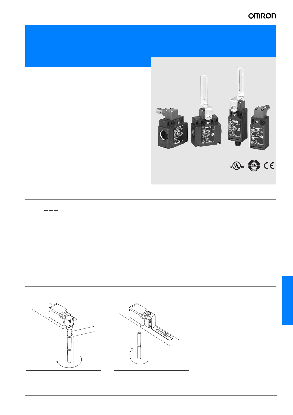
Miniature Safety-door Hinge Switch
D4NH
New series Safety-door Hinge
Switch Designed for sace saving
guaring in Machines and safety
Equipment
• Lineup includes three contact models with 2NC/1NO and
3NC contacts in addition to the 1NC/1NO, and 2NC versions. Version with MBB contacts meet applications for
avdanced requirements.
• M12-connector models are available, saving on labor and
simplifying maintenance.
• Standardized gold-clad contacts provide high contact reliability Can be used with both standard loads and microloads.
• Free of lead, cadmium, and hexavalent chrome, reducing the
burden on the environment.
Be sure to read the “Safety Precautions” on page G-214.
Note: Contact your sales representative for details on models with safety standard
certification.
Model Number Structure
D4NH-@@@
1
23
1. Conduit/Connector size
1: Pg13.5 (1-conduit)
2: G1/2 (1-conduit)
3: 1/2-14NPT (1-conduit)
4: M20 (1-conduit)
5: Pg13.5 (2-conduit)
6: G1/2 (2-conduit)
7: 1/2-14NPT (2-conduit)
8: M20 (2-conduit)
9: M12 connector (1-conduit)
2. Built-in Switch
A: 1NC/1NO (slow-action)
B: 2NC (slow-action)
C: 2NC/1NO (slow-action)
D: 3NC (slow-action)
E: 1NC/1NO (MBB contact) (slow-action)
F: 2NC/1NO (MBB contact) (slow-action)
3. Actuator
AS: Shaft
BC: Arm lever
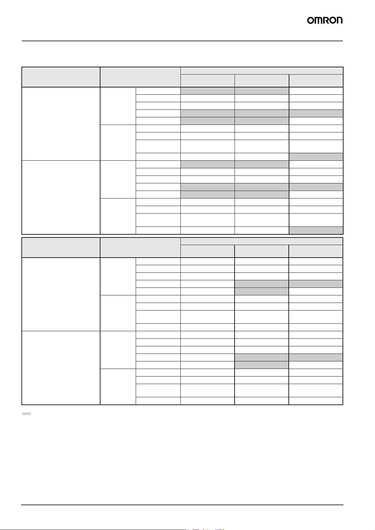
Application Examples (Protective Door Safety Measures)
Shaft Actuator Arm Lever Actuator
D4NH
G-207D4NH
Ordering Information
List of Models
Switches
Actuator Conduit size Built-in switch mechanism
Shaft 1-conduit Pg13.5
G1/2 D4NH-2AAS D4NH-2BAS D4NH-2CAS
1/2-14NPT D4NH-3AAS D4NH-3BAS D4NH-3CAS
M20
M12 connector
2-conduit Pg13.5 D4NH-5AAS D4NH-5BAS D4NH-5CAS
G1/2 D4NH-6AAS D4NH-6BAS D4NH-6CAS
1/2-14NPT
(See note 3.)
M20 D4NH-8AAS D4NH-8BAS
Arm lever 1-conduit Pg13.5
G1/2 D4NH-2ABC D4NH-2BBC D4NH-2CBC
1/2-14NPT D4NH-3ABC D4NH-3BBC D4NH-3CBC
M20
M12 connector
2-conduit Pg13.5 D4NH-5ABC D4NH-5BBC D4NH-5CBC
G1/2 D4NH-6ABC D4NH-6BBC D4NH-6CBC
1/2-14NPT
(See note 3.)
M20 D4NH-8ABC D4NH-8BBC
1NC/1NO
(Slow-action)
D4NH-1AAS D4NH-1BAS D4NH-1CAS
D4NH-4AAS D4NH-4BAS D4NH-4CAS
D4NH-9AAS D4NH-9BAS ---
D4NH-7AAS D4NH-7BAS D4NH-7CAS
D4NH-1ABC D4NH-1BBC D4NH-1CBC
D4NH-4ABC D4NH-4BBC D4NH-4CBC
D4NH-9ABC D4NH-9BBC ---
D4NH-7ABC D4NH-7BBC D4NH-7CBC
2NC
(Slow-action)
2NC/1NO
(Slow-action)
D4NH-8CAS
D4NH-8CBC
Actuator Conduit size Built-in switch mechanism
3NC
(Slow-action)
Shaft 1-conduit Pg13.5 D4NH-1DAS D4NH-1EAS D4NH-1FAS
G1/2 D4NH-2DAS D4NH-2EAS D4NH-2FAS
1/2-14NPT D4NH-3DAS D4NH-3EAS D4NH-3FAS
M20 D4NH-4DAS
M12 connector ---
2-conduit Pg13.5 D4NH-5DAS D4NH-5EAS D4NH-5FAS
G1/2 D4NH-6DAS D4NH-6EAS D4NH-6FAS
1/2-14NPT
(See note 3.)
M20 D4NH-8DAS D4NH-8EAS D4NH-8FAS
Arm lever 1-conduit Pg13.5 D4NH-1DBC D4NH-1EBC D4NH-1FBC
G1/2 D4NH-2DBC D4NH-2EBC D4NH-2FBC
1/2-14NPT D4NH-3DBC D4NH-3EBC D4NH-3FBC
M20 D4NH-4DBC
M12 connector ---
2-conduit Pg13.5 D4NH-5DBC D4NH-5EBC D4NH-5FBC
G1/2 D4NH-6DBC D4NH-6EBC D4NH-6FBC
1/2-14NPT
(See note 3.)
M20 D4NH-8DBC D4NH-8EBC D4NH-8FBC
Prefered types
D4NH-7DAS D4NH-7EAS D4NH-7FAS
D4NH-7DBC D4NH-7EBC D4NH-7FBC
1NC/1NO MBB
(Slow-action)
D4NH-4EAS D4NH-4FAS
D4NH-9EAS ---
D4NH-4EBC D4NH-4FBC
D4NH-9EBC ---
2NC/1NO MBB
(Slow-action)
Note: 1. It is recommended that M20 be used for Switches to be exported to Europe and 1/2-14NPT be used for Switches to be exported to North
American countries.
2. All models have slow-action contacts with approved direct opening mechanisms on NC contacts only.
3. The 1/2-14NPT 2-conduit models include an M20-to-1/2-14NPT changing adaptor.
G-208 Safety Sensors / Components
Specifications
Standards and EC Directives
• Conforms to the following EC Directives:
Machinery Directive
Low Voltage Directive
EN50047
EN1088
GS-ET-15
Approved Standards
Agency Standard File No.
TÜV Product
Service
UL (See note.) UL508, CSA C22.2 No.14 E76675
Note: Approval for CSA C22.2 No. 14 is authorized by the UL mark.
CCC (China Compulsory Certification) Mark
Agency Standard File No.
CQC GB14048.5 Under application
EN60947-5-1 (approved
direct opening)
B03 11 39656 061
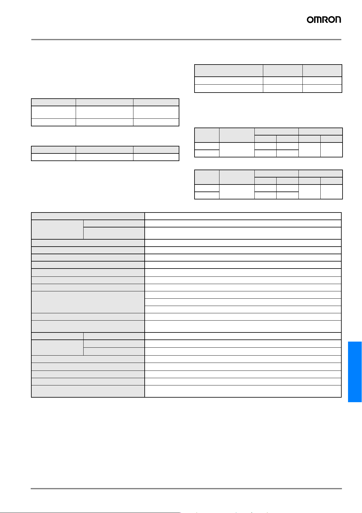
Approved Standard Ratings
TÜV (EN60947-5-1)
Utilization
Item
Rated operating current (I
Rated operating voltage (U
Note: Use a 10-A fuse type gI or gG that conforms to IEC269 as a short-circuit
protection device. This fuse is not built into the Switch.
category
) 3 A 0.27 A
e
e
UL/CSA (UL508, CSA C22.2 No. 14)
A300
Rated
voltage
120 VAC 10 A 60 A 6 A 7,200 VA 720 VA
240 VAC 30 A 3 A
Carry current Current Volt-amperes
AC-15 DC-13
) 240 V 250 V
Make Break Make Break
Q300
Rated
voltage
125 VDC 2.5 A 0.55 A 0.55 A 69 VA 69 VA
250 VDC 0.27 A 0.27 A
Carry current Current Volt-amperes
Make Break Make Break
Characteristics
Degree of protection (See note 3.) IP67 (EN60947-5-1)
Durability
(See note 4.)
Operating speed 2 to 360° /s (See note 6.)
Operating frequency 30 operations/minute max.
Contact resistance 25 mΩ max.
Minimum applicable load (See note 7.) Resistive load of 1 mA at 5 VDC (N-level reference value)
Rated insulation voltage (Ui) 300 V
Protection against electric shock Class II (double insulation)
Pollution degree (operating environment) Level 3 (EN60947-5-1)
Impulse withstand voltage (EN60947-5-1) Between terminals of the same polarity: 2.5 kV
Insulation resistance 100 MΩ min.
Contact gap Snap-action: 2 x 9.5 mm min
Vibration resistance Malfunction 10 to 55 Hz, 0.75-mm single amplitude
Shock resistance Destruction
Conditional short-circuit current 100 A (EN60947-5-1)
Rated open thermal current (Ith) 10 A (EN60947-5-1)
Ambient temperature Operating: −30° C to 70° C with no icing
Ambient humidity Operating: 95% max.
Weight Approx. 87 g (D4NH-1AAS)
Note: 1. The values in the table on the previous page are initial values.
2. Once a contact has been used to switch a standard load, it cannot be used for a load of a smaller capacity. Doing so may result in rough-
ening of the contact surface and contact reliability may be lost.
3. The degree of protection is tested using the method specified by the standard (EN60947-5-1). Confirm that sealing properties are suffi-
cient for the operating conditions and environment beforehand. Although the switch box is protected from dust or water penetration, do
not use the D4NH in places where foreign material such as dust, dirt, oil, water, or chemicals may penetrate through the head. Otherwise,
premature wear, Switch damage or malfunctioning may occur.
4. The durability is for an ambient temperature of 5°C to 35° C and an ambient humidity of 40% to 70%. For more details, consult your
OMRON representative.
5. If the ambient temperature is greater than 35° C, do not pass the 3-A, 250-VAC load through more than 2 circuits.
6. For safe use, make sure that the allowable operating speed is not exceeded.
7. This value will vary with the switching frequency, environment, and reliability level. Confirm that correct operation is possible with the ac-
tual load beforehand.
Mechanical 1,000,000 operations min.
Electrical 500,000 operations min. for a resistive load of 3 A at 250 VAC (See note 5.)
Malfunction
300,000 operations min. for a resistive load of 10 A at 250 VAC
Between terminals of different polarities: 4 kV
Between other terminals and uncharged metallic parts: 6 kV
Slow-action: 2 x 2 mm min
1,000 m/s
300 m/s
Approx. 97 g (D4NH-1ABC)
2
2
D4NH
G-209D4NH
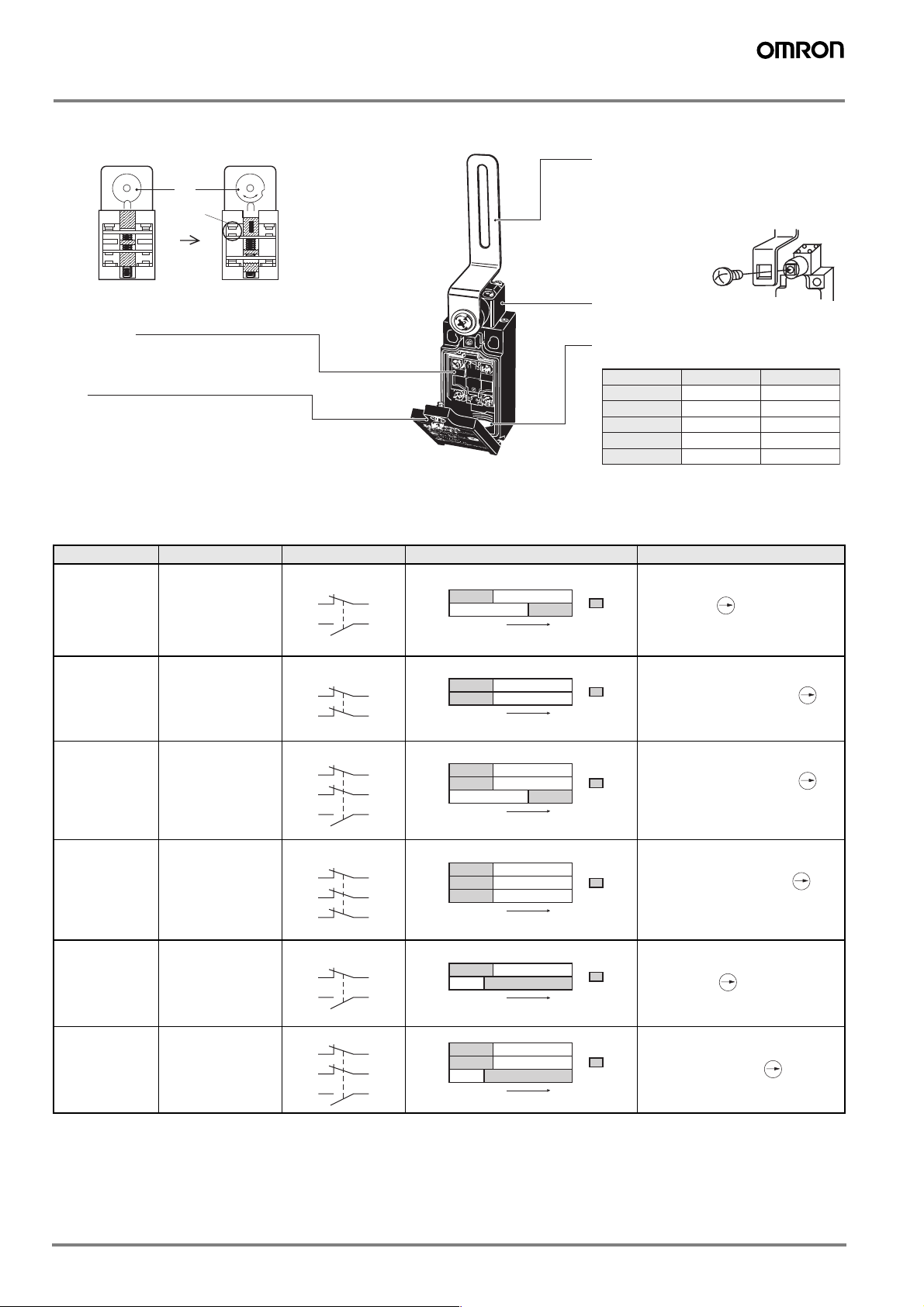
Structure, Names, and Functions
Structure (D4NH-@@BC)
Cam
When
opening
the guard
Guard Open
▲
Arm Lever
The arm lever is mounted upwards in the center
position before shipping. To change the position,
loosen the arm lever mounting screw, dismount
the arm lever, and mount the arm lever in the left
or right position.
The joint between the shaft and
arm lever is formed with formlock construction which remains
secure even when the
screw becomes loose.
Head
The head can be mounted in four directions.
Conduit
A wide variety of conduits is available.
Size 1-conduit 2-conduit
Pg13.5
G1/2
1/2-14NPT
M20
M12 Connector
Yes
Yes
Yes
Yes
Yes
Note: M12 connector types are not available for
Switches with three contacts.
Guard Closed
Forced
separation
of NC contacts
When the guard is opened, the cam that is directly coupled to
the shaft rotates to press the Switch in the direction shown by
the (vertical) arrow. This action separates the contacts to stop
the machine.
Built-in Switch
The built-in switch has a direct opening mechanism
that forcibly separates the NC contact even when
there is contact deposit.
Cover
The cover, with a hinge on its lower part, can be
opened by removing the screw of the cover, which
ensures ease of maintenance and wiring.
* The housing and head of the D4NH are made of resin. Use D4BS Miniature
Electromagnetic Lock Safety Door Limit Switches for applications requiring
safety door switches of tough, high-sealing, or oil-resistant construction.
Contact Form
Model Contact Contact form Operating pattern Remarks
D4NH-@A@ 1NC/1NO
Zb
11
33
12
34
11-12
33-34
Stroke
D4NH-@B@ 2NC
D4NH-@C@ 2NC/1NO
Zb
11
31
Zb
11
21
33 34
12
32
12
22
11-12
31-32
Stroke
11-12
21-22
33-34
Stroke
D4NH-@D@ 3NC
D4NH-@E@ 1NC/1NO MBB
D4NH-@F@ 2NC/1NO MBB
Zb
11
21
31 32
Zb
11
33
Zb
11
21
33 34
12
22
12
34
12
22
11-12
21-22
31-32
Stroke
11-12
33-34
Stroke
11-12
21-22
33-34
Stroke
Note: 1. Terminals are numbered according to EN50013. Contact forms are according to EN60947-5-1.
2. MBB (Make Before Break) contacts have an overlapping structure, so that before the normally closed contact (NC) opens, the normally
open contact (NO) closes.
Only NC contacts 11-12 have an
approved direct opening
ON
mechanism.
The terminals 11-12 and 33-34
can be used as unlike poles.
Only NC contacts 11-12 and
31-32 have an approved
ON
direct opening mechanism.
The terminals 11-12 and 31-32
can be used as unlike poles.
Only NC contacts 11-12 and
21-22 have an approved
direct opening mechanism.
ON
The terminals 11-12, 21-22, and
33-34 can be used as unlike
poles.
Only NC contacts 11-12, 21-22,
and 31-32 have an approved direct opening mechanism.
ON
The terminals 11-12, 21-22, and
31-32 can be used as unlike
poles.
Only NC contacts 11-12 have an
approved direct opening
ON
mechanism.
The terminals 11-12 and 33-34
can be used as unlike poles.
Only NC contacts 11-12 and
21-22 have an approved direct
ON
opening mechanism.
The terminals 11-12, 21-22 and
33-34 can be used as unlike poles.
Yes
Yes
Yes
Yes
---
G-210 Safety Sensors / Components
 Loading...