

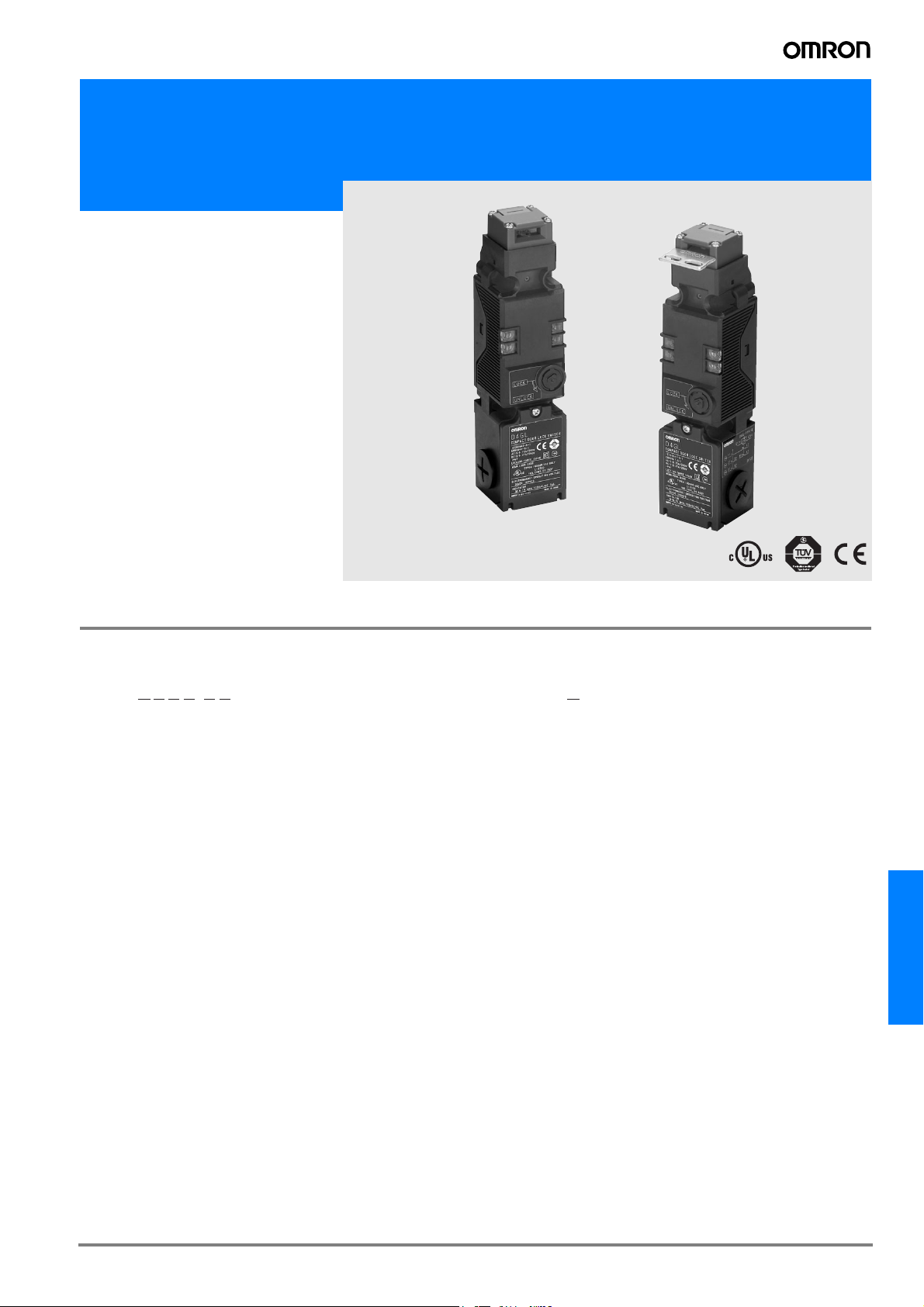
Guard Lock Safety-door Switch
D4GL
Environment-friendly
Switch with Direct
Opening Contacts
• Contains no harmful substances, such
as lead or cadmium, reducing the burden on the environment.
• Slim safety-door switch with an electromagnetic lock or unlock mechanism.
• Models with 4-contact and 5-contact
built-in switches are available.
• Capable of a holding force of 1,000 N
min.
• Can be used for either standard loads
or microloads.
• Lineup includes models with a conduit
size of M20.
• Patent and industrial design approval
pending.
Model Number Structure
Model Number Legend
Switch
D4GL-@@@@-@@
4 5
123
1. Conduit Size
1: Pg13.5
2: G1/2
4: M20
2. Built-in Switch (with Door Open/Closed Detection Switch and
Lock Monitor Switch Contacts)
A: 1NC/1NO slow-action contacts plus 1NC/1NO slow-action
contacts
B: 1NC/1NO slow-action contacts plus 2NC slow-action con-
tacts
C: 2NC slow-action contacts plus 1NC/1NO slow-action con-
tacts
D: 2NC slow-action contacts plus 2NC slow-action contacts
E: 2NC/1NO slow-action contacts plus 1NC/1NO slow-action
contacts
F: 2NC/1NO slow-action contacts plus 2NC slow-action con-
tacts
G: 3NC slow-action contacts plus 1NC/1NO slow-action con-
tacts
H: 3NC slow-action contacts plus 2NC slow-action contacts
3. Head Mounting Direction and Material
F: Four mounting directions possible (Front-side mounting at
time of delivery)/plastic
4. Door Lock and Release
A: Mechanical lock/24-VDC solenoid release
G: 24-VDC solenoid lock/mechanical release
5. Indicator
B: 24 VDC (orange/green LED indicator)
6. Release Key Type
Blank:Standard release key
4: Special release key
6
Operation Key
D4DS-K@
1
1. Operation Key Type
1: Horizontal mounting
2: Vertical mounting
3: Adjustable mounting (horizontal)
5: Adjustable mounting (horizontal/vertical)
\
D4GL
G-171D4GL
Ordering Information
List of Models
Switches (Operation Keys are sold separately.)
: Models with approved direct opening contacts. Prefered stock item*
Contact configuration
Head ma-
terial
Plastic Standard
Release
key type
Solenoid voltage/
indicator
Solenoid: 24 VDC
Orange/green LED:
24 VDC
Lock and release
types
Mechanical lock
Solenoid release
Solenoid lock
Mechanical release
detection switch and lock
monitor switch contacts)
Approved direct opening
1NC/1NO+1NC/1NO
1NC/1NO+2NC
2NC+1NC/1NO
2NC+2NC
2NC/1NO+1NC/1NO
2NC/1NO+2NC
3NC+1NC/1NO
3NC+2NC
1NC/1NO+1NC/1NO
1NC/1NO+2NC
2NC+1NC/1NO
2NC+2NC
2NC/1NO+1NC/1NO
2NC/1NO+2NC
3NC+1NC/1NO
3NC+2NC
(door open/closed
(slow-action)
NC contact
Conduit size Model
Pg13.5
G1/2
M20
Pg13.5
G1/2
M20
Pg13.5
G1/2
M20
Pg13.5
G1/2
M20
Pg13.5
G1/2
M20
Pg13.5
G1/2
M20
Pg13.5
G1/2
M20
Pg13.5
G1/2
M20
Pg13.5
G1/2
M20
Pg13.5
G1/2
M20
Pg13.5
G1/2
M20
Pg13.5
G1/2
M20
Pg13.5
G1/2
M20
Pg13.5
G1/2
M20
Pg13.5
G1/2
M20
Pg13.5
G1/2
M20
D4GL-1AFA-A*
D4GL-2AFA-A
D4GL-4AFA-A*
D4GL-1BFA-A
D4GL-2BFA-A
D4GL-4BFA-A
D4GL-1CFA-A*
D4GL-2CFA-A
D4GL-4CFA-A*
D4GL-1DFA-A
D4GL-2DFA-A
D4GL-4DFA-A
D4GL-1EFA-A
D4GL-2EFA-A
D4GL-4EFA-A*
D4GL-1FFA-A
D4GL-2FFA-A
D4GL-4FFA-A
D4GL-1GFA-A
D4GL-2GFA-A
D4GL-4GFA-A
D4GL-1HFA-A
D4GL-2HFA-A
D4GL-4HFA-A
D4GL-1AFG-A*
D4GL-2AFG-A
D4GL-4AFG-A*
D4GL-1BFG-A
D4GL-2BFG-A
D4GL-4BFG-A
D4GL-1CFG-A*
D4GL-2CFG-A
D4GL-4CFG-A*
D4GL-1DFG-A
D4GL-2DFG-A
D4GL-4DFG-A
D4GL-1EFG-A
D4GL-2EFG-A
D4GL-4EFG-A*
D4GL-1FFG-A
D4GL-2FFG-A
D4GL-4FFG-A
D4GL-1GFG-A
D4GL-2GFG-A
D4GL-4GFG-A
D4GL-1HFG-A
D4GL-2HFG-A
D4GL-4HFG-A
G-172 Safety Sensors / Components
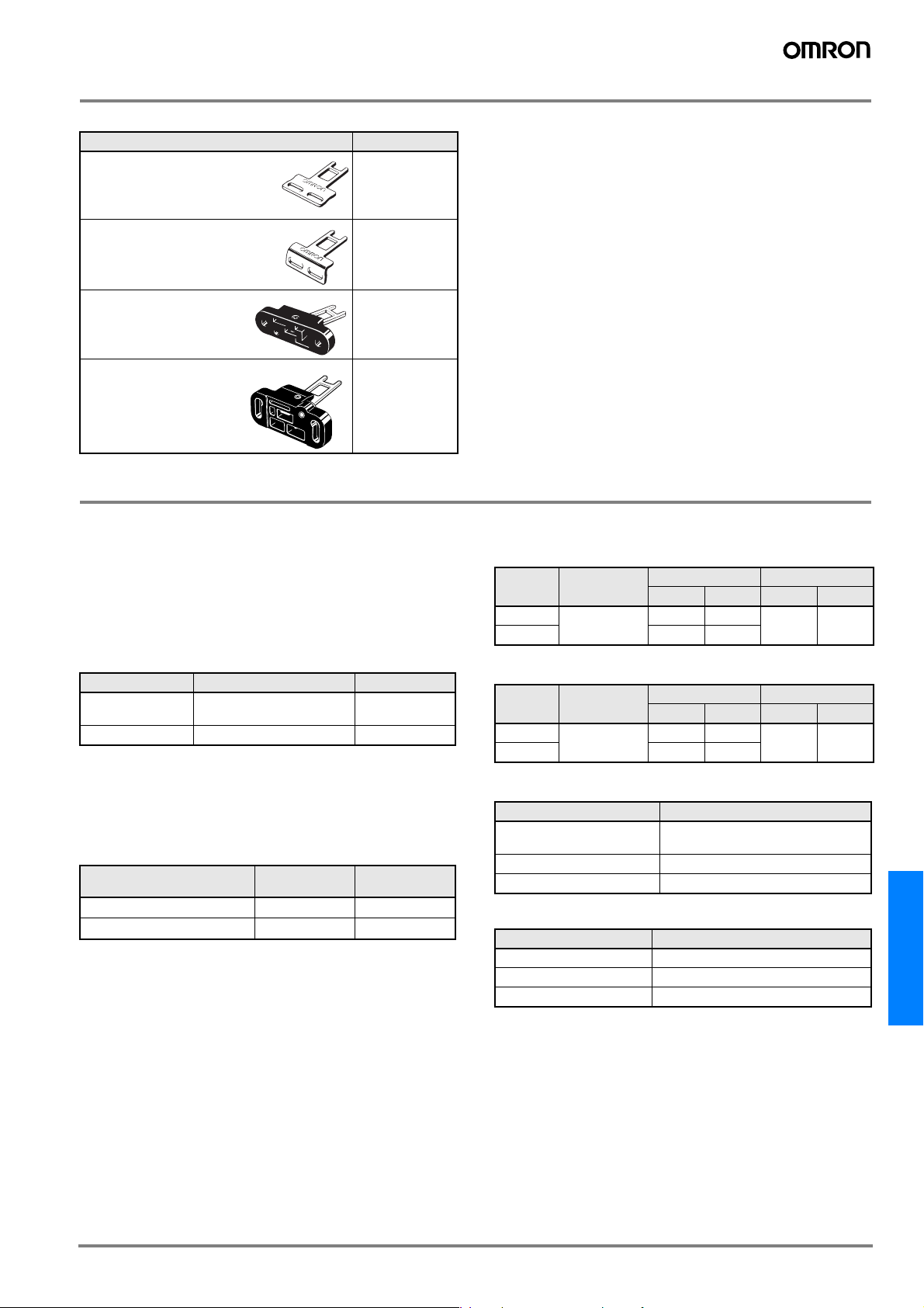
Operation Keys (Order Separately)
Type Model
Horizontal mounting
D4DS-K1
Vertical mounting
Adjustable mounting
(Horizontal)
Adjustable mounting
(Horizontal/Vertical)
D4DS-K2
D4DS-K3
D4DS-K5
Specifications
Standards and EC Directives
Applicable EC Directives and Standards
• Machinery Directive
• Low Voltage Directive
• EN1088
• EN60204-1
• GS-ET-19
Approved Standards
Agency Standard File No.
TÜV Product
Service
UL (See note 2.) UL508, CSA C22.2 No.14 E76675
Note: 1. Consult your OMRON representative for details.
2. Approval for CSA C22.2 No. 14 is authorized by the UL
mark.
Approved Standard Ratings
TÜV (EN60947-5-1)
Item
Rated operating current (I
Rated operating voltage (U
Note: Use a 10-A fuse type gI or gG that conforms to IEC269 as a short-circuit
protection device.
EN60947-5-1 (approved
direct opening)
Utilization
category
) 0.75 A 0.27 A
e
e
AC-15 DC-13
) 240 V 250 V
(See note 1.)
UL/CSA (UL508, CSA C22.2 No. 14)
C300
Rated
voltage
120 VAC 2.5 A 15 A 1.5 A 1,800 VA 180 VA
240 VAC 7.5 A 0.75 A
Carry current Current Volt-amperes
Make Break Make Break
Q300
Rated
voltage
125 VAC 2.5 A 0.55 A 0.55 A 69 VA 69 VA
250 VAC 0.27 A 0.27 A
Carry current Current Volt-amperes
Make Break Make Break
Solenoid Coil Characteristics
Item 24 VDC
Rated operating voltage
(100% ED)
Current consumption Approx. 200 mA
Insulation Class F (130° C max.)
24 VDC ±10%
Indicator Characteristics
Item LED
Rated voltage 24 VDC
Current leakage Approx. 3 mA
Color (LED) Orange/Green
D4GL
G-173D4GL
Characteristics
Degree of protection (See note 2.) IP67 (EN60947-5-1)
Durability
(See note 3.)
Mechanical 1,000,000 operations min.
Electrical 500,000 operations min. for a resistive load of 4 mA at 24 VDC;
Operating speed 0.05 to 0.5 m/s
Operating frequency 30 operations/minute max.
Rated frequency 50/60 Hz
Contact gap 2 x 2 mm min.
Direct opening force (See note 5.) 60 N min. (EN60947-5-1)
Direct opening travel (See note 5.) 10 mm min. (EN60947-5-1)
Holding force (See note 6.) 1,000 N min.
Insulation resistance 100 MΩ min. (at 500 VDC)
Minimum applicable load (See note 7.) Resistive load of 4 mA at 24 VDC (N-level reference value)
Rated insulation voltage (Ui) 300 V (EN60947-5-1)
Conventional enclosed thermal current (I
the
Impulse withstand voltage (EN60947-5-1) Between terminals of the same polarity 2.5 kV
Conditional short-circuit current 100 A (EN60947-5-1)
Pollution degree (operating environment) 3 (EN60947-5-1)
Protection against electric shock Class II (double insulation)
Closed-circuit counterelectromotive force 1,500 V max. (EN60947-5-1)
Contact resistance 25 mΩ max. (initial value)
Vibration resis-
Malfunction 10 to 55 Hz, 0.75-mm single amplitude
tance
Shock resistance Destruction
Malfunction
Ambient temperature Operating: −10° C to 55° C with no icing
Ambient humidity Operating: 95% max.
Weight Approx. 400 g (D4GL-1AFA-A)
Note: 1. The above values are initial values.
2. The degree of protection is tested using the method specified by the standard (EN60947-5-1). Confirm that sealing properties are suffi-
cient for the operating conditions and environment beforehand. Although the switch box is protected from dust or water penetration, do
not use the D4GL in places where foreign material may penetrate through the key hole on the head, otherwise Switch damage or malfunctioning may occur.
3. The durability is for an ambient temperature of 5°C to 35° C and an ambient humidity of 40% to 70%. For more details, consult your OM-
RON representative.
4. If the ambient temperature is greater than 35° C, do not pass the 1-A, 125-VAC load through more than 2 circuits.
5. These figures are minimum requirements for safe operation.
6. This figure is based on the GS-ET-19 evaluation method.
7. This value will vary with the switching frequency, environment, and reliability level. Confirm that correct operation is possible with the actual
load beforehand.
(This applies for the Switch only. The degree of protection for the key hole is IP00.)
150,000 operations min. for a resistive load of 1 A at 125 VAC in 2 circuits and 4 mA at
24 VDC in 2 circuits (See note 4.)
) 2.5 A (EN60947-5-1)
Between terminals of different polarities 4 kV
Between the solenoid and uncharged metallic parts and be-
---
tween the solenoid and ground
24-VDC solenoid 0.8 kV
Between other terminals and uncharged metallic parts and be-
4 kV
tween other terminals and ground
2
min.
2
min.
1,000 m/s
300 m/s
G-174 Safety Sensors / Components
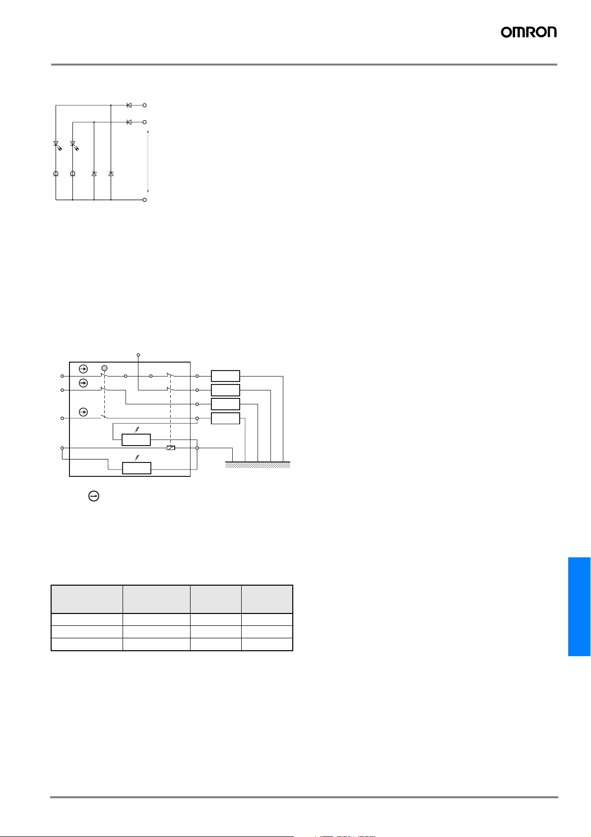
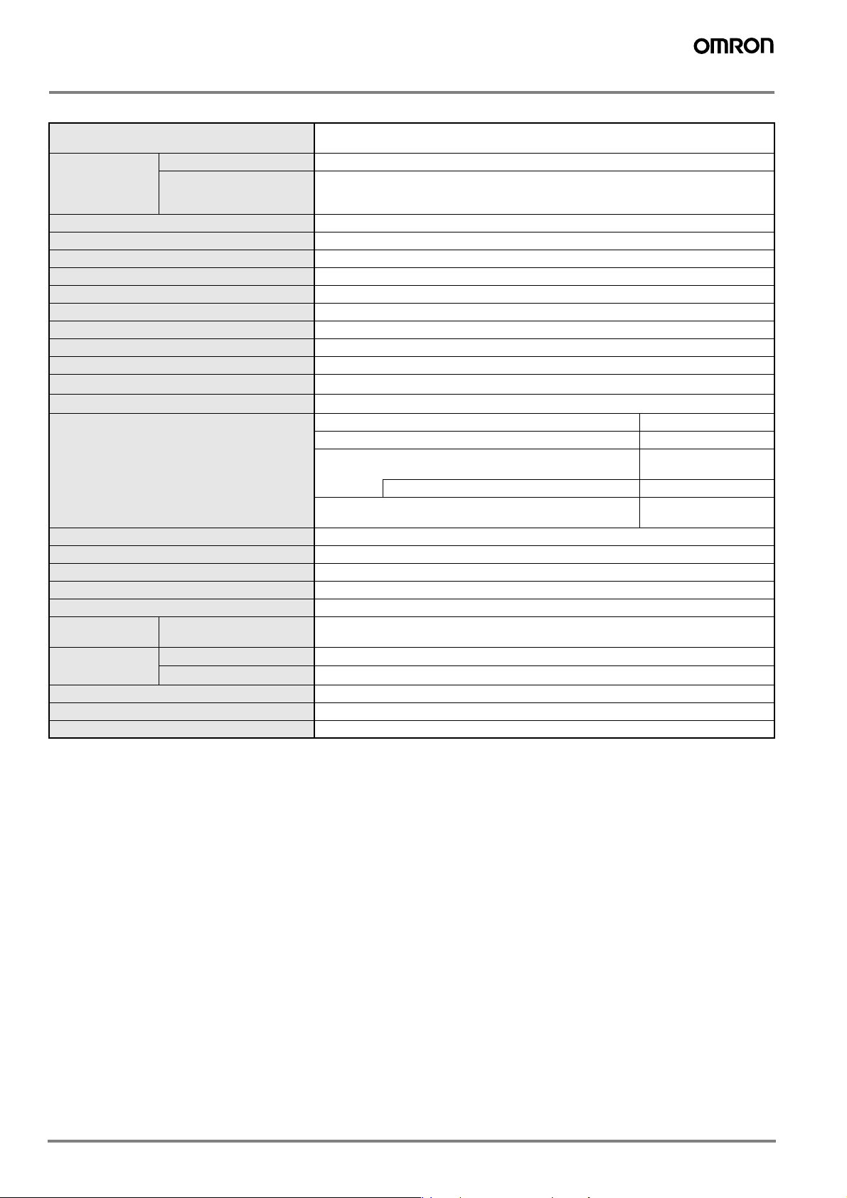
Connections
Indicator
Internal Circuit Diagram
D
D
LED
LED
(Green)
(Orange)
Green (+)
Orange (+)
CRD CRD ZD ZD
5 to 24V DC
COM (−)
Circuit Connection Example
• Terminals 12 and 41 are connected internally and so connect ter-
minals 11 and 42 for safety-circuit input. (BIA GS-ET-19)
• Connect terminals 21 and 22 and terminals 51 and 52 in series
when using as safety-circuit input (redundancy circuit for terminals
11 and 12 and terminals 41 and 42 above). Connect the terminals
individually when using as auxiliary-circuit input (e.g., terminals 21
and 22 for safety-door open/closed monitoring and terminals 51
and 52 for monitoring the lock status).
• In the following connection example, terminals 21 and 22 and ter-
minals 51 and 52 are used as auxiliary-circuit input.
Connection Example for D4GL-1HFA-A
51
11
21
31
O1 (Green)
E1
12 41
Indicator
(Green)
O2
(Green)
42
Safety
circuit
52
Auxiliary
circuit
22
Auxiliary
circuit
32
Auxiliary
circuit
E2
Indicator
O3 (Orange)
(Orange)
O4 (Orange)
• Direct opening contacts used as safety-circuit input are indicated
with the mark. Terminals 11 and 12 and terminals 21 and 22
are direct opening contacts.
• Connect the indicators in parallel to the auxiliary circuits or termi-
nals E1 and E2.
• Although the 3 lines are connected at the time of delivery, rewire
them as necessary for the application.
• The following table shows the connection configuration required to
make the green indicator light when the door is closed and the
orange indicator light when the solenoid turns ON.
Indicator Terminal
number
Lead wire
color
Connected
terminal
number
Green indicator O1 Green 32
Orange indicator O2 Orange E1
Common O3 Black E2
• If an indicator is connected in parallel to a direct opening contact,
when the indicator breaks, a short-circuit current will be generated,
possibly resulting in an installation malfunction.
• Do not switch standard loads for more than 2 circuits at the same
time. Otherwise, the level of insulation may decrease.
• The solenoid has polarity. Be sure to connect terminals with the
correct polarity.
D4GL
G-175D4GL
 Loading...