

Page 1
Small Safety Limit Switch
D4F
A Smaller Limit Switch than
Ever Previously Produced.
Ideal for Applications to
Small-scale Machinery and
Equipment
• A noticeable reduction to 1/4 the size of OMRON's
conventional model.
• High-sensitivity safety limit switch.
• Built-in switches with two- or four-contact construction
are available.
• Degree of protection: IP67 (EN60947-5-1)
• Patent and design pending.
Features
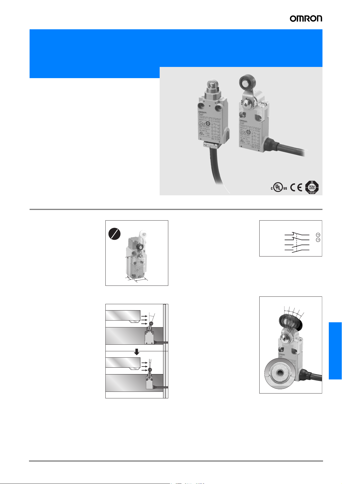
A Dramatic Reduction in Size
The volume is reduced to one quarter of the volume of our company's
conventional types of limit switches
(30 (W) × 18 (L) × 60 mm (H)).
Optimal for the downsizing of machinery and equipment.
High-sensitivity and Spacesaving
The conventional types of limit
switches with a direct opening
mechanism required 18 degrees for
a movement until operation because its direct opening point is long
(Our company's conventional types
of limit switches).
The D4F requires 6 degrees to respond.
On the table that allows machine
tools etc. to move at an increasing
speed, the moment the dog pushes
the actuator, the D4F responds.
With the development of smaller
versions of machines, the D4F
saves space and fits in a smaller
space.
Compared with conventional type
1
4
60 mm
18 mm
30 mm
18˚
6˚
Four-contact Construction is Available
D4F models of two-contact construction (1NC/1NO and 2NC) and
those of four-contact construction
(2NC/2NO and 4NC) are available.
The auxiliary contact can be used
for monitoring input of control circuits and indicator lighting.
<2NC/2NO>
Safety contact 11
Safety contact 21
Auxiliary contact
Auxiliary contact
33
43
Positioning in Steps of 9 Degrees
For a roller lever type of switch,
grooves are incised on the body and
the cam of the actuator, to allow positioning in steps of 9 degrees.
Zb
12
22
34
44
9
˚
9
˚
9
˚
9
˚
D4F
G-259D4F
Page 2
Standards and EC Directives
• Conforms to the following EC Directives:
Machinery Directive
Low Voltage Directive
EN60204-1
EN1088
EN50047
EN81
EN115
GS-ET-15
JIS C 8201-5-1
Ordering Information
Model Number Legend
D4F-@@-@@
1 2 3 4
1. Built-in Switch
1: 1NC/1NO (slow-action)
2: 2NC (slow-action)
3: 2NC/2NO (slow-action)
4: 4NC (slow-action)
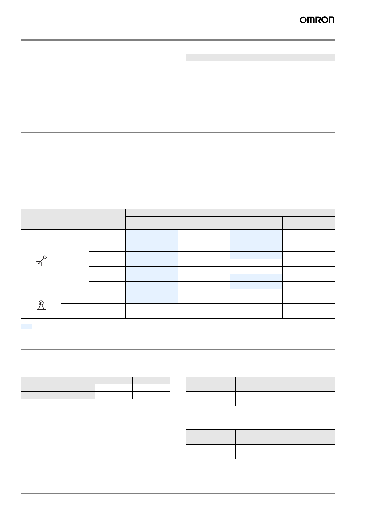
List of Models
2. Actuator
02: Roller plunger
(Metallic roller)
20: Roller lever
(Metallic lever, resin roller)
Approved Standards
Agency Standards File No.
TÜV Product
service
UL (See note 2.) UL508
Note: 1. Contact your Omron sales representative.
2. Approval has been obtained for CSA C22.2 No. 14
under UL.
3. Cable Length
1: 1 m
3: 3 m
5: 5 m
EN60947-5-1
(Direct opening: approved)
CSA C22.2 No.14
4. Pull-outing direction of cable
R: Horizontal
D: Vertical
(See note 1.)
E76675
Actuator Cable
Roller lever (Metallic lever, resin
roller)
Roller plunger
(Metallic roller)
length
1 m Horizontal
3 m Horizontal
5 m Horizontal
1 m Horizontal
3 m Horizontal
5 m Horizontal D4F-102-5R D4F-202-5R D4F-302-5R D4F-402-5R
Cable
direction
Vertical
Vertical
Vertical
Vertical
Vertical
Vertical D4F-102-5D D4F-202-5D D4F-302-5D D4F-402-5D
1NC/1NO
(slow-action)
D4F-120-1R D4F-220-1R D4F-320-1R D4F-420-1R
D4F-120-1D D4F-220-1D D4F-320-1D D4F-420-1D
D4F-120-3R D4F-220-3R D4F-320-3R D4F-420-3R
D4F-120-3D D4F-220-3D D4F-320-3D D4F-420-3D
D4F-120-5R D4F-220-5R D4F-320-5R D4F-420-5R
D4F-120-5D D4F-220-5D D4F-320-5D D4F-420-5D
D4F-102-1R D4F-202-1R D4F-302-1R D4F-402-1R
D4F-102-1D D4F-202-1D D4F-302-1D D4F-402-1D
D4F-102-3R D4F-202-3R D4F-302-3R D4F-402-3R
D4F-102-3D D4F-202-3D D4F-302-3D D4F-402-3D
Prefered items
Specifications
Approved Standard Ratings
TÜV (EN60947-5-1)
Item Utilization category AC-15 DC-13
Rated operating current (Ie) 0.75 A 0.27 A
Rated operating voltage (Ue) 240 V 250 V
Note: Use a 10-A fuse type gI or gG that conforms to IEC269 as a
short-circuit protection device.
Built-in switch
2NC
(slow-action)
2NC/2NO
(slow-action)
4NC
(slow-action)
UL/CSA (UL508, CSA C22.2 No. 14)
C300
Rated
voltage
120 VAC 2.5 A 15 A 1.5 A 1,800 VA 180 VA
240 VAC 7.5 A 0.75 A
Q300
Carry
current
Current Volt-amperes
Make Break Make Break
Rated
voltage
125 VDC 2.5 A 0.55 A 0.55 A 69 VA 69 VA
250 VDC 0.27 A 0.27 A
Carry
current
Current Volt-amperes
Make Break Make Break
G-260 Safety Sensors / Components
Page 3
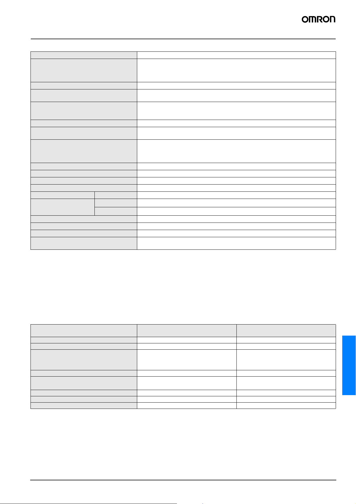
Characteristics
Degree of protection (See note 1.) IP67 (EN60947-5-1)
Durability (See note 2.) Mechanical: 10,000,000 times min.
Operating speed 1 mm/s to 0.5 m/s
Operating frequency Mechanical: 120 operations/minute
Insulation resistance 100 MΩ min. (at 500 VDC) between terminals of the same polarities, between terminals of dif-
Minimum applicable load (See note 4.) 4-mA resistive load at 24 VDC, 4 circuits (Level N reference value)
Contact resistance (See note 5.) 300 mΩ max. (initial value with 1-m cable), 500 mΩ max. (initial value with 3-m cable),
Dielectric strength Between terminals of same polarities: Uimp 2.5 kV (EN60947-5-1)
Conditional short-circuit current 100 A (EN60947-5-1)
Pollution degree (operating environment) 3 (EN60947-5-1)
Conventional free air thermal current (Ith) 2.5 A (EN60947-5-1)
Protection against electric shock Class I (with a ground wire)
Vibration resistance Malfunction 10 to 55 Hz, 0.75-mm single amplitude
Shock resistance Destruction
Malfunction
Ambient temperature Operating: −30°C to 70°C (with no icing)
Ambient humidity Operating: 95% max.
Cable UL2464 No. 22 AWG, finishing O.D.: 8.3 mm
Weight Approx. 190 g (D4F-102-1R, with 1-m cable)
Electrical: 1,000,000 times min. (4-mA resistive load at 24 VDC, 4 circuits)
150,000 times min. (1-A resistive load at 125 VAC, 2 circuits / 4-mA resistive load at 24 VDC,
2 circuits) (See note 3.)
Electrical: 30 operations/minute
ferent polarities, between current-carrying metal parts and grounds, and between each terminal and non-current carrying metal parts
700 mΩ max. (initial value with 5-m cable)
Between terminals of different polarities: Uimp 4 kV (EN60947-5-1)
Between current-carrying metal parts and grounds: Uimp 4 kV (EN60947-5-1)
Between each terminal and non-current carrying metal parts: Uimp 4 kV (EN60947-5-1)
2
2
min.
min.
1,000 m/s
300 m/s
Approx. 220 g (D4F-120-1R, with 1-m cable)
Note: 1. The degree of protection shown above is based on the test method specified in EN60947-5-1. Be sure to confirm in advance the sealing
performance under the actual operating environment and conditions.
2. Durability values are calculated at an operating temperature of 5°C to 35°C, and an operating humidity of 40% to 70%. Contact your
OMRON sales representative for more detailed information on other operating environments.
3. When the ambient temperature is 35°C or higher, do not apply 1 A at 125 VAC to more than two circuits.
4. The value will vary depending on factors such as the switching frequency, the ambient environment, and the reliability level.
Be sure to confirm correct operation with the actual load before application.
5. The contact resistance was measured with 0.1 A at 5 to 8 VDC with a fall-of-potential method.
Operating Characteristics
Slow-action (1NC/1NO, 2NC, 2NC/2NO, and 4NC)
Operating Characteristics
Operating force max.: OF (See note 1.) 5 N 12 N
Release force min.: RF (See note 2.) 0.5 N 1.5 N
Pretravel: PT1 (11-12 and 21-22)
: PT1 (31-32 and 41-42)
: PT2 (See note 3.)
Overtravel min.: OT 40° 3.2 mm
Operating position: OP (11-12 and 21-22)
: OP (31-32 and 41-42)
Total travel: TT (See note 3.) (55°) (4.5 mm)
Min. direct opening travel: DOT (See note 4.) 18° 1.8 mm
Min. direct opening force: DOF 20 N 20 N
Note: 1. The OF value is the maximum load that opens an NC contact (11-12, 21-22, 31-32, 41-42).
2. The RF value is the minimum load that closes an NC contact (11-12, 21-22, 31-32, 41-42).
3. The PT2 and TT values are reference values.
4. The D4F is used in accordance with EN81 and EN115 at a minimum DOT of 30° and 2.8 mm.
Model
6±3° (NC)
9±3° (NC)
(12°) (NO)
——
——
D4F-@20-@R
D4F-@20-@D
D4F-@02-@R
D4F-@02-@D
1 mm max. (NC)
1.3 mm max. (NC)
(1.2 mm) (NO)
29.4±1 mm
29±1 mm
D4F
G-261D4F
Page 4

Nomenclature
Lever
Improved safety of the lever-setting (Form lock configuration).
Many grooves are incised on the lever and the rotating shaft
Head
The plunger type of actuator can be used in a
normal direction and reverse direction.
that mesh with each other to prevent a slip between the lever
and the rotating shaft.
The lever can be set for positioning in steps of 9 degrees.
Cable
Built-in Switch
Has a direct opening mechanism separating
The cable can be pulled out in a horizontal
direction or in a vertical direction.
the contacts when the NC contacts are welded.
Operation
Contact Form
Model Contact Diagram Remarks
D4F-1@-@@ 1NC/1NO
(slow-action)
D4F-2@-@@ 2NC
(slow-action)
D4F-3@-@@ 2NC/2NO
(slow-action)
D4F-4@-@@ 4NC
(slow-action)
Zb
11
33
Zb
11
21
Zb
11
21
33
43
Zb
11
21
31
41
11-12
12
33-34
34
11-12
12
21-22
22
11-12
12
21-22
22
33-34
43-44
34
44
11-12
12
21-22
22
31-32
41-42
32
42
Stroke
Stroke
Stroke
Stroke
Only NC contact 11-12 has an approved
ON
direct opening mechanism.
The terminals 11-12 and 33-34 can be used
as unlike poles.
NC contacts 11-12 and 21-22 have an
ON
approved direct opening mechanism.
The terminals 11-12 and 21-22 can be used
as unlike poles.
NC contacts 11-12 and 21-22 have an
approved direct opening mechanism.
The terminals 11-12, 21-22, 33-34 and
ON
43-44 can be used as unlike poles.
NC contacts 11-12, 21-22, 31-32 and 41-42
have an approved direct opening
mechanism.
ON
The terminals 11-12, 21-22, 31-32 and
41-42 can be used as unlike poles.
Direct Opening Mechanism
1NC/1NO Contact (slow-action)
Fixed contact (NC)
Contact spring
Return spring
Movable contact
Fixed contact (NO)
Plunger
Conforms to EN60947-5-1 Direct Opening .
(Only the NC contacts have a direct opening function.)
When metal weld occurs, the NC contacts are separated from each
other by pushing in the plunger.
G-262 Safety Sensors / Components
Page 5

Dimensions
Note: 1. All units are in millimeters unless otherwise indicated.
2. Each dimension has a tolerance of 0.4 mm unless otherwise specified.
Roller lever (Metallic lever, resin roller)
D4F-@20-@R
(30.8)
25.5
9
18.5
(42.7)
0.1
±
20
17.5-dia. × 6.8,
resin roller
R24.7
Two, 4.4-dia.
8-dia. countersinking,
depth 4
(14.4-dia.)
(35)
Roller plunger (Metallic roller)
D4F-@02-@R
Pretravel
Operating
27.5
30
position
8.8
(42.7)
12-dia. × 4.4,
Sintered stainless steel roller
Two, 4.4-dia.
8-dia. countersinking,
depth 4
0.1
±
20
(14.4-dia.)
(35)
30
(11.4)
UL2464
No. 22 AWG,
finishing O.D.: 8.3 mm
Roller lever (Metallic lever, resin roller)
D4F-@20-@D
17.5-dia. × 6.8,
resin roller
R24.7
Two, 4.4-dia.
±
20
(17.6)
30
0.1
8-dia. countersinking,
depth 4
(16.7)
UL2464
No. 22 AWG,
finishing O.D.: 8.3 mm
2
18.5
(42.7)
(7.9)
(30.8)
25.5
18
30
(11.4)
UL2464
No. 22 AWG,
finishing O.D.: 8.3 mm
18
Roller plunger (Metallic roller)
D4F-@02-@D
Pretravel
Operating
27.5
18
30
position
8.8
(42.7)
(7.9)
12-dia. × 4.4,
Sintered stainless steel roller
Two, 4.4-dia.
8-dia. countersinking,
depth 4
0.1
±
20
(16.7)
UL2464
No. 22 AWG,
finishing O.D.: 8.3 mm
(17.6)
30 2
18
D4F
G-263D4F
Page 6

Precautions
NOTICE
Be sure to connect a ground line, otherwise an electric shock may
occur.
If the D4F is to be used as a switch in an emergency stop circuit or in
a safety circuit for preventing accidents resulting in injuries or deaths,
use NC contacts with a forced release mechanism and set the D4F
so that it will operate in direct opening mode.
For safety, install the Switch using one-way rotational screws or other
similar means to prevent it from easily coming off. Protect the D4F
with an appropriate cover and post a warning sign near the D4F in
order to ensure the safety.
To prevent the D4F from damage due to circuit short-circuiting,
connect a fuse with a breaking current 1.5 to 2 times larger than the
rated current of the D4F in series to the D4F.
If the D4F is used under EN-approved conditions, use a gI or gG 10A fuse approved by IEC269.
Actuation of the Switch over a long time may deteriorate parts of the
Switch and a return failure may result. Be sure to check the
condition of the Switch regularly.
Do not supply electric power when wiring.
Do not use the Switch where explosive gas, flammable gas, or any
other dangerous gas may be present.
Keep the electrical load below the rated value.
Never wire to a wrong terminal.
Be sure to evaluate the Switch under actual working conditions after
installation.
Do not drop or disassemble the D4F.
Do not use in closely contacted mounting.
Do not use the Switch as a stopper.
Conduct periodic inspections.
Do not use it in an activating circuit. (Use it as a safety signal.)
Contacts of the D4F can be used both for ordinary load and
microload; however, once the contact is opened or closed with an
ordinary load, it cannot be used for a load smaller than that. The
contact surface may be rough, which impairs the reliability of
contacting.
Handling of cables
Cables cannot be flexed repeatedly.
The cable is fixed with sealing materials on the bottom of the switch.
When excessive force may be imposed on the cable, fasten the
cable with a fixing unit at a distance of 50 mm from the bottom of the
switch as shown.
Do not pull or press the cable at an excessive force (50 N max.).
When bending the cable, secure the cable with more than 45-mm
bending radius so as not to cause damage to the insulator or sheath
of the cable. Doing so may result in current leakage or burning.
Operating Environment
Keep the D4F away from oil and water, as these may enter the
casing. (Though the switch construction complies with IP67 and
prevents immersion of water even when held in water for a specified
time, its use is not guaranteed when it is immersed in a liquid.)
Make sure in advance that the environment is suitable, with the
presence of oil, water, or chemicals, as these may cause the seal to
deteriorate, resulting in faulty contact, faulty isolation, current
leakage, or burning.
Do not use the D4F in the following locations:
• Locations subject to corrosive gas
• Locations with severe changes in temperature
• Locations with excessive humidity that may cause condensation
• Locations with excessive vibration
• Locations that may be covered with processing chips or dust
• Locations subject to high temperature or excessive humidity
Correct Use
Operating Environment
The D4F is for indoor use only.
Do not use the D4F outdoors. Otherwise, the D4F may malfunction.
Durability
The life of the D4F will vary with the switching conditions. Before
applying the D4F, test the D4F under actual operating conditions and
be sure to use the D4F in actual operation within switching times that
will not lower the performance of the D4F.
Tightening Torque
Be sure to tighten each screw of the D4F properly, otherwise the
D4F may soon malfunction.
No. Type Proper tightening torque
1 Lever mounting screw (M5) 2.4 to 2.8 N·m
2 Body mounting screw (M4) 1.18 to 1.37 N·m
1
2
Mounting
Use two M4 screws and washers to mount the D4F securely. The
50 mm
Fixing unit
When wiring, be sure to prevent penetration of a liquid such as water
or oil through the cable end.
Bending radius
more than 45 mm
D4F can be mounted more securely with proper tightening torque.
Mounting Holes (Unit: mm)
Two, 4.2-dia. or M4 screw hole
0.1
±
20
G-264 Safety Sensors / Components
Page 7

Changing the lever angle
Unfasten the screw that holds the lever to set the position of the lever
at any angle through 360° (in steps of 9°).
After unfastening the screws that hold the lever, mount the lever the
other way (normal side or reverse side). Set an angle of the lever to
complete adjustment within a range in which the lever does not touch
the switch body.
<4NC>
Safety contact Brown 21
Auxiliary contact Orange 31
Auxiliary contact Pink 41
Safety contact Blue 11
Green/yellow ground
Zb
12 Blue/white
22 Brown/white
32 Orange/white
42 Pink/white
Wiring
Identifying Wires
Identify wires according to the color (with or without white lines) of
the insulation on the wire.
Cross section
Insulation
1
2
9
8 3
7
4
5
6
Core insulator (black)
Wire Colors
No. Color of insulation No. Color of insulation
1 Blue/white 6 Brown
2 Orange /white 7 Pink
3 Pink/white 8 Orange
4 Brown/white 9 Blue
5 Green/yellow
Note: "Blue/white, orange/white, pink/white, or brown/white" means
that the cover is blue, orange, pink, or brown with a white line.
Terminal Numbers
Identify terminal numbers based on the color (with or without white
lines) of the insulation on the wire.
The safety and auxiliary contacts of D4F models of four-terminal
contact construction and those of two-terminal contact construction
are described below.
The safety contacts are direct-opening NC contacts (11-12 and 21-
22); they are used for safety circuits, and each of them is indicated
with the appropriate mark .
Auxiliary contacts are used to check (to monitor) the operating state
of the switch, which are equivalent to NO contacts (33-34 and 43-44)
or NC contacts (31-32 and 41-42).
The NC contacts 31-32 and 41-42 of auxiliary contacts (orange or
pink) can be used as safety contacts.
<1NC/1NO>
Safety contact Blue 11
Auxiliary contact Orange 33
Green/yellow ground
External insulation sheath
Zb
12 Blue/white
34 Orange/white
Cut the black core insulator and all unused wires at the end of the
external insulation sheath when wiring the cable.
Operating
To set the plunger stroke correctly, press-fit the plunger until the top
of the pushing surface comes between two grooves on the plunger.
Pushing surface
Proper range
Grooves
To set the roller lever stroke correctly, push the dog and cam until the
the lance point comes within the range of the convex part that is the
correct setting position.
Lance point
Convex part
Proper range
Others
Actuating the switch from an angle other than 90 degrees to the
switch face may deform or damage the actuator, or deform or
damage the rotary spindle, so make sure that the dog is straight.
Dog
Dog
Dog
Dog
<2NC>
Auxiliary contact Brown 21
<2NC/2NO>
Safety contact Brown 21 22 Brown/white
Auxiliary contact Orange 33
Auxiliary contact Pink 43
Safety contact Blue 11
Green/yellow ground
Safety contact Blue 11
Green/yellow ground
Zb
Zb
12 Blue/white
22 Brown/white
12 Blue/white
34 Orange/white
44 Pink/white
Do not remove the head. Otherwise, a failure may occur.
To avoid telegraphing, take the following precautions.
1. Set the switch to operate in one direction.
2. Modify the rear end of the dog to an angle of 15° to 30° as shown
below or to a secondary-degree curve.
θ
θ≥30˚
θ
15˚≤θ≤30˚
3. Modify the circuit so as not to detect the wrong operating signals.
SI Units Conversion Table
To fully comply with international standards, this catalogue is based
on the International System of Units (SI).
G-265D4F
D4F
Page 8

ALL DIMENSIONS SHOWN ARE IN MILLIMETERS.
To convert millimeters into inches, multiply by 0.03937. To convert grams into ounces, multiply by 0.03527.
Cat. No. C124-E1-Cat04-01A
In the interest of product improvement, specifications are subject to change without notice.
G-266 Safety Sensors / Components
 Loading...