

Omron D4E-N DATASHEET
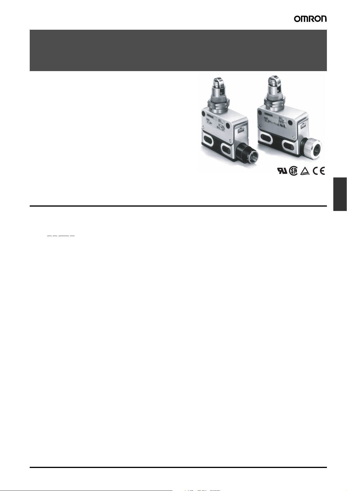
Small Sealed Switch
D4E-@N
Slim and Compact Switch with Better Seal
and Ensuring Longer Service Life than D4E
• Flat springs with an improved lever ratio of the built-in switch ensure smooth snap action and long life expectancy.
• Protection cover protects the built-in switch from dust and oil.
Plunger incorporates a tough seal cap that lasts for a long time.
• One touch connector eliminates need for tedious wiring operations and reduces downtime for wiring and maintenance (models with standard, easy-to-use screw terminals are also
available).
• Minute load model with gold cladding is optimal for electronic
control.
• Molded terminal types as well as molded terminal types with operating indicator lamps are available for screw terminal systems.
• No difference in mounting pitch and characteristics between
D4E-@N and D4E models.
Model Number Structure
■ Model Number Legend
D4E-@@@@@N
1 2 3 4
1. Rated Current
1: 5 A at 125 VAC
(1 A at 125 VAC/30 VDC for model with a connector)
2: 0.1 A at 125 VAC
(0.1 A at 125 VAC/30 VDC for model with a connector)
2. Actuator
A: Roller plunger
B: Crossroller plunger
C: Plunger
D: Sealed roller plunger
E: Sealed crossroller plunger
F: Sealed plunger
G: Roller lever
H: One-way action roller lever
3. Terminals
00: AC connector
10: DC connector
20: Screw terminals without a cable
21: Screw terminals with a cable (right-hand)
22: Screw terminals with a cable (left-hand)
23: Molded terminals with a cable (right-hand)
24: Molded terminals with a cable (left-hand)
(Cable is S-FLEX VCTF 3 m)
4. Operation Indicator
L: Neon lamp (250 VAC)
L1: LED (12 VDC)
L2: LED (24 VDC)
L3: LED (48 VDC)
Note: 1. Only the molded terminal models can be equipped with an
operation indicator.
2. Desired Switches may not be manufactured depending on
the combination between molds and indicators. Contact our
sales representative for further information.
Limit
Switches
Small Sealed Switch D4E-@NF-31
Ordering Information
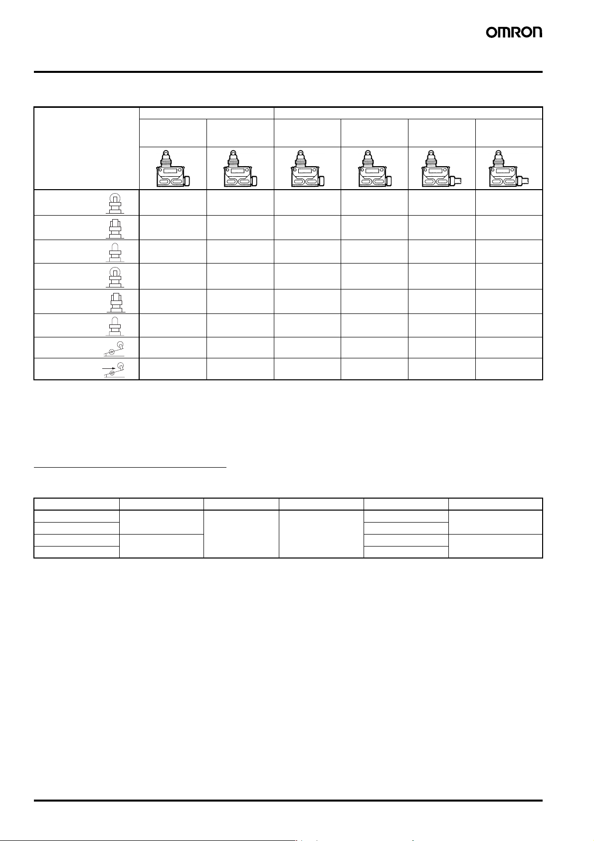
■ List of Models
One-touch connector type Screw terminal type
General-
purpose
Actuator
Roller plunger
Crossroller
plunger
Plunger
Sealed roller plunger
Sealed crossroller
plunger
Sealed plunger
Roller lever
One-way action
roller lever
Note: 1. When ordering, specify the current type by replacing the blank box of the model number with 0 for AC connector or 1 for DC connector.
2. Approved by UL and CSA.
3. For the plunger and lever actuator models, the NC and NO terminal indicators are reversed.
4. Cold tolerance specifications are available for actuator models with an A, B, C, G, or H in the model number. When ordering, add C to
the model number.
For example: D4E-1A20N → D4E-1A20N-C
D4E-1A@0N D4E-2A@0N D4E-1A20N (see
D4E-1B@0N D4E-2B@0N D4E-1B20N (see
D4E-1C@0N D4E-2C@0N D4E-1C20N (see
D4E-1D@0N D4E-2D@0N D4E-1D20N (see
D4E-1E@0N D4E-2E@0N D4E-1E20N (see
D4E-1F@0N D4E-2F@0N D4E-1F20N (see
D4E-1G@0N D4E-2G@0N D4E-1G20N (see
D4E-1H@0N D4E-2H@0N D4E-1H20N (see
Micro load General-
purpose without
cable
note 2)
note 2)
note 2)
note 2)
note 2)
note 2)
note 2)
note 2)
Micro load
without cable
D4E-2A20N D4E-1A21N D4E-2A21N
D4E-2B20N D4E-1B21N D4E-2B21N
D4E-2C20N D4E-1C21N D4E-2C21N
D4E-2D20N D4E-1D21N D4E-2D21N
D4E-2E20N D4E-1E21N D4E-2E21N
D4E-2F20N D4E-1F21N D4E-2F21N
D4E-2G20N D4E-1G21N D4E-2G21N
D4E-2H20N D4E-1H21N D4E-2H21N
General-
purpose with
cable
Micro load with
cable
Accessories (Order Separately)
Plug
Model Current Type No. of conductors Cable length Applicable models
XS2F-A421-D90-A AC Straight 4 2 m D4E-@@00N
XS2F-A421-G90-A 5 m
XS2F-D421-D80A DC 2 m D4E-@@10N
XS2F-D421-G80-A 5 m
F-32 Small Sealed Switch D4E-@N
Specifications
■ Approved Standards
Agency Standard File No.
UL UL508 E76675
CSA CSA C22.2 No. 14 LR45746
TÜV Rheinland EN60947-5-1 R9551015
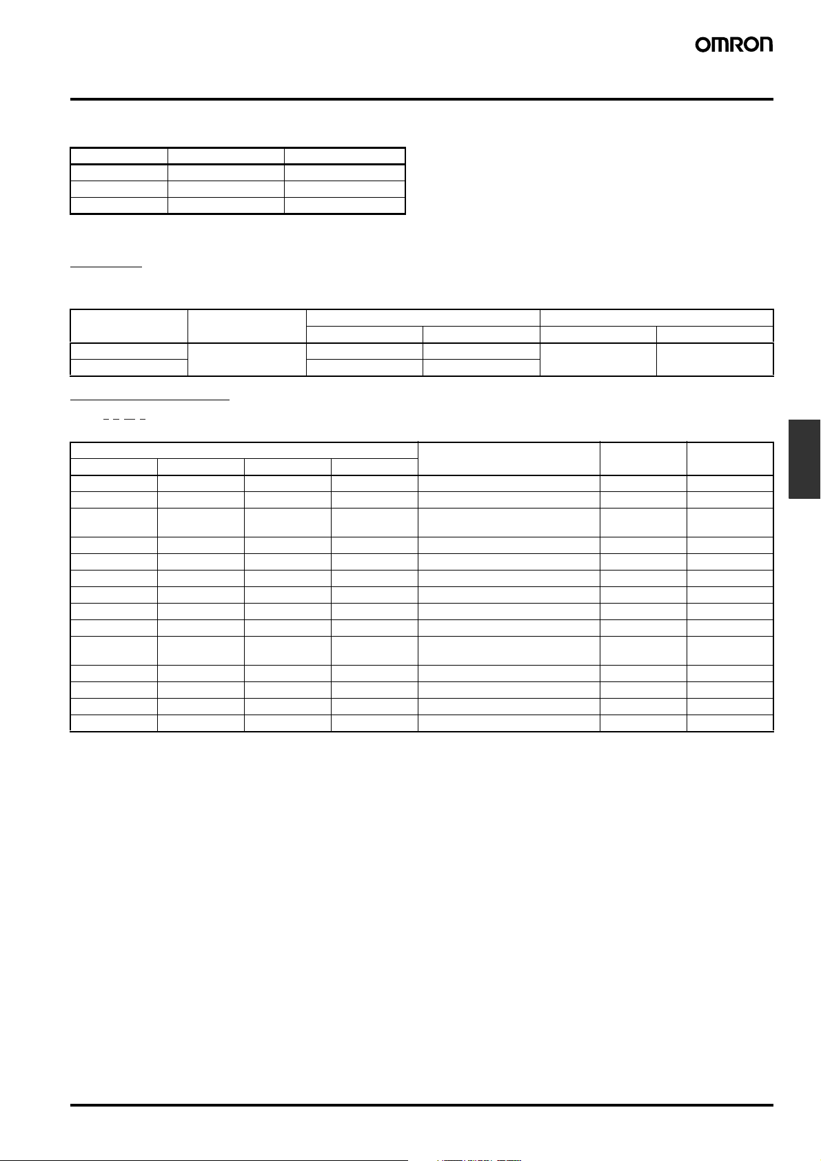
■ Approved Standard Ratings
UL, CSA
A300
Voltage Carry current Current Volt-amperes
Make Break Make Break
120 V 10 A 60 A 6 A 7,200 VA 720 VA
240 V 30 A 3 A
TÜV (EN60947-5-1)
1 G 23 L N
D4E-
I II III IV
Model Applicable category and ratings Thermal
I II III IV
1 @ 00 AC-14 0.5 A/125 VAC 5 A --1 @ 10 DC-12 0.5 A/30 VDC 5 A --1 @ 20, 21, 22 AC-15 2A/250 VAC
1 @ 23, 24 L AC-15 2A/250 VAC 5 A Neon lamp
1 @ 23, 24 L1 DC-12 2A/12 VDC 5 A LED
1 @ 23, 24 L2 DC-12 2A/24 VDC 5 A LED
1 @ 23, 24 L3 DC-12 2A/48 VDC 5 A LED
2 @ 00 AC-14 0.1A/125 VAC 0.5 A --2 @ 10 DC-12 0.1A/30 VDC 0.5 A --2 @ 20, 21, 22 AC-14 0.1A/125 VAC
2 @ 23, 24 L AC-14 0.1A/125 VAC 0.5 A Neon lamp
2 @ 23, 24 L1 DC-12 0.1A/12 VDC 0.5 A LED
2 @ 23, 24 L2 DC-12 0.1A/24 VDC 0.5 A LED
2 @ 23, 24 L3 DC-12 0.1A/48 VDC 0.5 A LED
Note: 1. @: Actuator variation of item II
2. AC-14 0.5 A/125 VAC means as follows:
Applicable category: AC-14
Rated operating current (I
Rated operating voltage (U
): 0.5 A
e
): 125 VAC
e
DC-12 2A/48 VDC
DC-12 0.1A/48 VDC
current (I
5 A ---
0.5 A ---
the
Indicator
)
Limit
Switches
Small Sealed Switch D4E-@NF-33
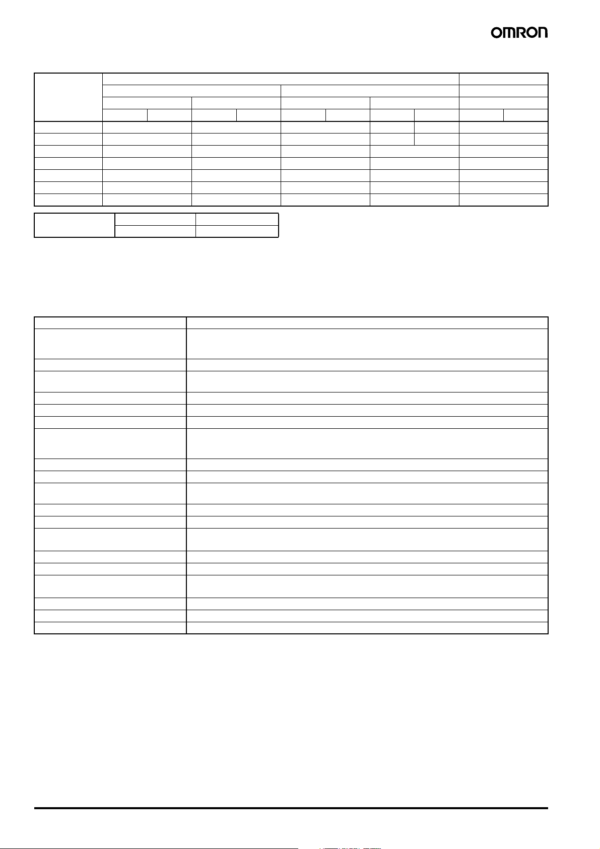
■ Ratings
Rated voltage General-purpose Micro load
Non-inductive load Inductive load Non-inductive load
Resistive load Lamp load Inductive load Motor load Resistive load
NC NO NC NO NC NO NC NO NC NO
125 VAC 5 (1) A 1.5 (1) A 3 (1) A 2 (1) A 1 (1) A 0.1 A
250 VAC 5 (1) A 1.5 (1) A 3 (1) A 1 A 0.5 A --8 VDC 5 (1) A --- 1.5 (1) A --- 0.1 A
14 VDC 5 (1) A --- 1.5 (1) A --- 0.1 A
30 VDC 5 (1) A --- 1.5 (1) A --- 0.1 A
125 VDC 0.5 A --- 0.05 A --- --250 VDC 0.25 A --- 0.03 A --- ---
Inrush current NC 10 A max.
NO 10 A max.
Note: 1. The above current ratings are for a standard current and the values in parentheses are for models with a connector.
2. Inductive loads have a power factor of 0.4 min. (AC) and a time constant of 7 ms max. (DC).
3. Lamp load has an inrush current of 10 times the steady-state current.
4. Motor load has an inrush current of 6 times the steady-state current.
■ Characteristics
Degree of protection IP67
Durability (see note 3) Mechanical: 10,000,000 operations min.
Operating speed 0.1 mm to 0.5 m/sec
Operating frequency Mechanical: 120 operations/min
Rated frequency 50/60 Hz
Insulation resistance 100 MΩ min. (at 500 VDC)
Contact resistance 15 mΩ max. (initial value)
Dielectric strength 1,000 VAC, 50/60 Hz for 1 min between terminals of same polarity
Rated insulation voltage (Ui) 250 VAC
Switching overvoltage 1,000 VAC max. (EN60947-5-1)
Pollution degree
(operating environment)
Short-circuit protective device (SCPD) 10 A fuse (type gG or gI, IEC269 approved)
Conditional short-circuit current 100 A (EN60947-5-1)
Conventional enclosed thermal current
)
(I
the
Protection against electric shock Class II (grounding not required with double insulation)
Vibration resistance Malfunction: 10 to 55 Hz, 1.5-mm double amplitude
Shock resistance
Ambient temperature Operating: –10°C to 80°C (with no icing)
Ambient humidity Operating: 95% max.
Weight Approx. 86 g (in case of roller plunger)
Note: 1. The above values are initial values.
2. The above ratings may vary depending on the model. Contact your OMRON representative for further details.
3. Durability values are calculated at an operating temperature of 5°C to 35°C, and an operating humidity of 40% to 70%. Contact your
OMRON sales representative for more detailed information on other operating environments.
Electrical: 500,000 operations min. (5 A at 250 VAC, resistive load)
Electrical: 30 operations/min
1,500 VAC, 50/60 Hz for 1 min/Uimp at 2.5 kV (EN60947-5-1) between current-carrying metal parts
and ground, and between each terminal and non-current-carrying metal part
3 (EN60947-5-1)
5 A (EN60947-5-1)
Destruction: 1,000 m/s
Malfunction: 300 m/s
5,000,000 operations min. (10 mA at 24 VDC, resistive load)
2
min.
2
min.
F-34 Small Sealed Switch D4E-@N
■ Operating Characteristics
)
Model D4E-1A@@N
OF max. 11.77 N 11.77 N 11.77 N 11.77 N 11.77 N
RF min. 4.90 N 4.90 N 4.90 N 4.90 N 4.90 N
PT max. 1.5 mm 1.5 mm 1.5 mm 1.5 mm 1.5 mm
OT min. 3 mm 3 mm 3 mm 3 mm 3 mm
MD (reference
value)
OP 31.4±0.8 mm 31.4±0.8 mm 25.4±0.8 mm 41.3±0.8 mm 41.3±0.8 mm
Model D4E-1F@@N
OF max. 11.77 N 3.92 N 3.92 N
RF min. 4.90 N 0.78 N 0.78 N
PT max. 1.5 mm 2 mm 2 mm
OT min. 3 mm 4 mm 4 mm
MD (reference
value)
OP 30±0.8 mm 23.1±0.8 mm 34.3±0.8 mm
Note: The values given in parentheses are reference values.
D4E-2A@@N
(0.1 mm) (0.1 mm) (0.1 mm) (0.1 mm) (0.1 mm)
D4E-2F@@N
(0.1 mm) (0.3 mm) (0.3 mm)
D4E-1B@@N
D4E-2B@@N
D4E-1G@@N
D4E-2G@@N
D4E-1C@@N
D4E-2C@@N
D4E-1H@@N
D4E-2H@@N
D4E-1D@@N
D4E-2D@@N
D4E-1E@@N
D4E-2E@@N
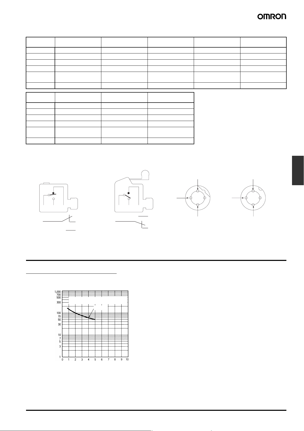
■ Contact Form
Screw Terminal Type
Plunger
Lever
Connector Type
AC
NC
DC
NC
Limit
Switches
COM NO NC COM NC NO
(COM) 1
2 (NC)
4 (NO)
(COM) 1
Engineering Data
Electrical Durability (cosφ=1)
Operating temperature: 5°C to 30°C
Operating humidity: 40% to 70%.
Operating frequency: 30 operations/min
(cosφ= 1)
250 VAC
operations)
4
2
COM
4 (NO)
2 (NC)
EN60947-5-1EN60947-5-1
3
1
4
NO
COM
2
3
1
4
NO
Durability (x10
Switching current (A
Small Sealed Switch D4E-@NF-35
 Loading...