

Page 1

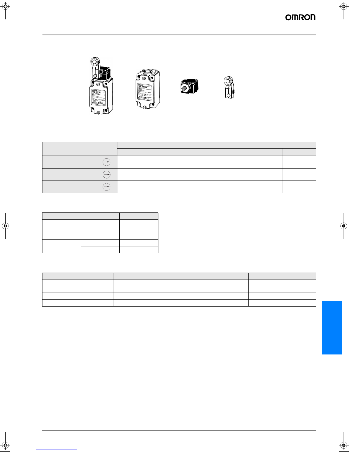
Safety Limit Switch
D4B-#N
• Snap-action or slow-action contact for
accurate switching with safe operation
via a direct opening mechanism with
metal deposition between mating contacts.
• Two sets of contacts: one (NC) for safety category circuit and the other (NO)
for control circuit.
• Contacts opened by direct opening
mechanism (NC contacts only), thus
preventing faulty operation due to factors such as metal deposition.
• Wide standard operating temperature
range:
–40°C to 80°C (standard type).
• Safety of lever settings ensured using a
mechanism that engages a gear between the operating position indicator
plate and the lever.
• Equipped with a mechanism that indicates the applicable operating zone, as
well as push-button switching to control
left and right motion.
• Conforms to EN (TÜV) standards corresponding to the CE marking.
• 3-conduit switches are available.
• Metric conduit types available.
Model Number Structure
Model Number Legend
D4B-####N
1 2 3
1. Conduit
1: PG13.5 (1-conduit)
2: G1/2 (PF1/2) (1-conduit)
3: 1/2-14NPT (1-conduit)
4: M20
5: PG13.5 (3-conduit)
6: G1/2 (PF1/2) (3-conduit)
7: 1/2-14NPT (3-conduit)
8: M20 (3-conduit)
2. Built-in Switch
1: 1NC/1NO (snap-action)
3: 1NC/1NO (slow-action) gold-plated contacts
5: 1NC/1NO (slow-action) (see note)
A: 2NC (slow-action)
B: 2NC (slow-action) gold-plated contacts
Note: Excluding D4B-##81N and D4B-##87N models.
3. Actuator
00: Switch box (without head)
11: Roller lever (standard)
16: Adjustable roller lever
17: Adjustable rod lever
1R: Roller lever
(conventional D4B-compatible)
70: Top plunger
71: Top roller plunger
81: Coil spring
87: Plastic rod
N
@
D4B-
G-243D4B-@N
Page 2
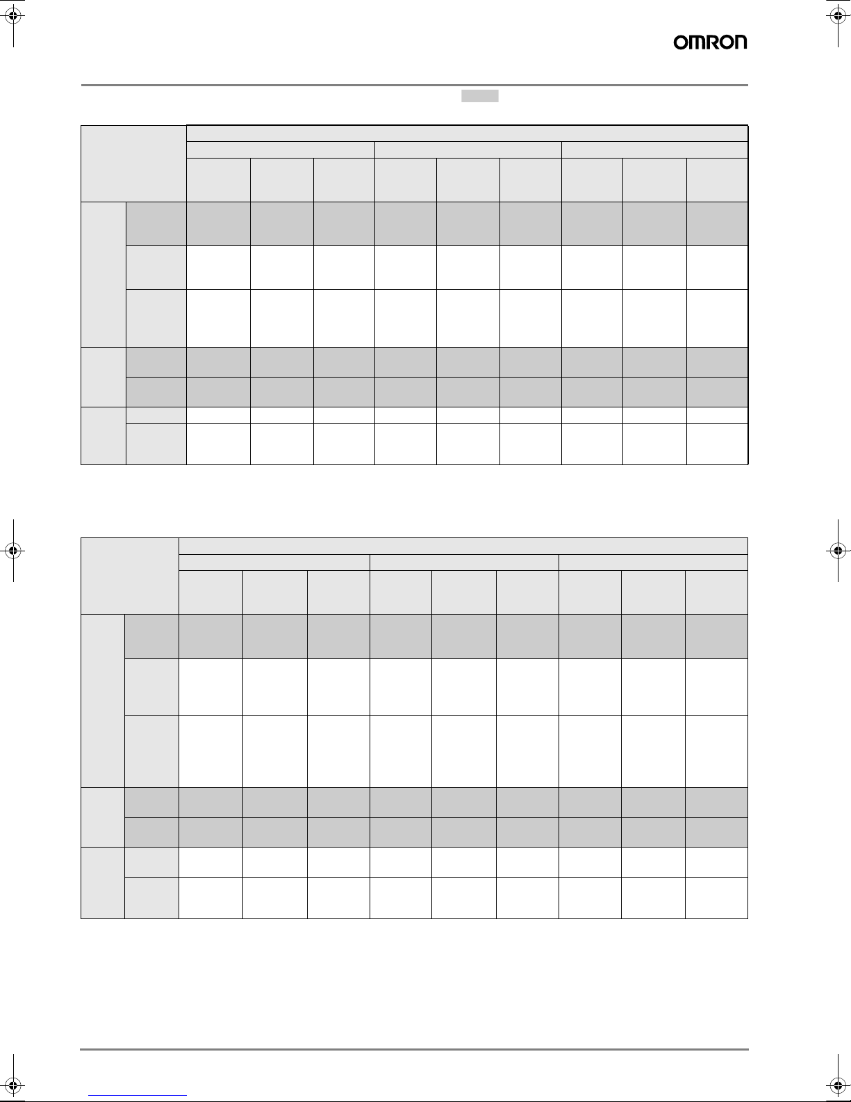
Ordering Information
List of Models Safety limit switch, mechanical form lock
Switches (EN50041)
Conduit size
PG13.5 (see note 2) G1/2 M20
1NC/1NO
(Snapaction)
D4B-1111N D4B-1511N
D4B-1116N D4B-1516N
D4B-1117N D4B-1517N
D4B-1170N D4B-1570N
D4B-1171N D4B-1571N
1NC/1NO
(Slow-
action)
2NC
(Slow-
action)
D4B-1A11N D4B-2111N
D4B-1A16N D4B-2116N
D4B-1A17N D4B-2117N
D4B-1A70N D4B-2170N
D4B-1A71N D4B-2171N
D4B-1A81N D4B-2181N
D4B-1A87N D4B-2187N
1NC/1NO
(Snapaction)
1NC/1NO
(Slow-
action)
D4B-2511N
D4B-2516N
D4B-2517N
D4B-2570N
D4B-2571N
---
---
2NC
(Slow-
action)
D4B-2A11N D4B-4111N
D4B-2A16N D4B-4116N
D4B-2A17N D4B-4117N
D4B-2A70N D4B-4170N
D4B-2A71N D4B-4171N
D4B-2A81N D4B-4181N
D4B-2A87N D4B-4187N
1NC/1NO
(Snapaction)
1NC/1NO
(Slow-
action)
D4B-4511N
D4B-4516N
D4B-4517N
D4B-4570N
D4B-4571N
---
---
2NC
(Slow-
action)
D4B-4A11N
D4B-4A16N
D4B-4A17N
D4B-4A70N
D4B-4A71N
Side
rotary
Top
plunger
Wobble
lever
(see
note 1)
Actuator
Roller
lever
(form A)
Adjustable
roller lever
(see note 1)
Adjustable
rod lever
(form D)
(see note 1)
Plain
(form B)
Roller
(form C)
Coil spring D4B-1181N ---
Plastic rod D4B-1187N ---
Note: 1. Mechanically speaking, these models are basic limit switches.
2. The D4B-#N is a Limit Switch conforming to European standards, and PG13.5 is commonly used in Europe.
3-conduit Switch
Conduit size
Actuator
Side
rotary
Top
plunger
Wobble lever
(see
note 1)
Roller
lever
(form A)
Adjustable roller
lever (see
note 1)
Adjustable
rod lever
(form D)
(see note
1)
Plain
(form B)
Roller
(form C)
Coil
spring
Plastic
rod
D4B-5111N D4B-5511N
D4B-5116N D4B-5516N
D4B-5117N D4B-5517N
D4B-5170N D4B-5570N
D4B-5171N D4B-5571N
D4B-5181N ---
D4B-5187N ---
PG13.5 (see note 2) G1/2 M20
1NC/1NO
(Snapaction)
1NC/1NO
(Slow-
action)
2NC
(Slow-
action)
D4B-5A11N D4B-6111N
D4B-5A16N D4B-6116N
D4B-5A17N D4B-6117N
D4B-5A70N D4B-6170N
D4B-5A71N D4B-6171N
D4B-5A81N D4B-6181N
D4B-5A87N D4B-6187N
1NC/1NO
(Snapaction)
1NC/1NO
(Slow-
action)
D4B-6511N
D4B-6516N
D4B-6517N
D4B-6570N
D4B-6571N
---
---
2NC
(Slow-
action)
D4B-6A11N D4B-8111N
D4B-6A16N D4B-8116N
D4B-6A17N D4B-8117N
D4B-6A70N
D4B-6A71N D4B-8171N
D4B-6A81N
D4B-6A87N
1NC/1NO
(Snapaction)
--- --- ---
--- --- ---
--- --- ---
1NC/1NO
(Slow-
action)
--- ---
--- ---
--- ---
---
2NC
(Slowaction)
D4B-8A71N
Note: 1. Mechanically speaking, these models are basic limit switches.
2. The D4B-#N is a Limit Switch conforming to European standards, and M20/PG13.5 is commonly used in Europe.
3. The wobble lever models are ordinary limit switches and are not approved under EN, GS, and SUVA’s Direct Opening Certificate.
G-244 Safety Sensors / Components
Page 3
Replacement Part
Because the D4B-#N employs a block mounting construction, the switch box, operating head, and lever (side rotary type only) may be ordered as
a complete assembly or individually as replacement parts. (Replacement parts are not available as a switch box and head assembly or as a head
and lever assembly.)
Switch box
=++
D4B-2100Nex. D4B-2111N
=
Switch Box
PG13.5 G1/2 1/2-14NPT PG13.5 G1/2 1/2-14NPT
1NC/1NO
(Snap-action)
1NC/1NO
(Slow-action)
2NC
(Slow-action)
Operating Heads
Actuator Type Model
Side rotary Standard D4B-0010N
Top plunger
Wobble lever
Plain D4B-0070N
Roller D4B-0071N
Coil spring D4B-0081N
Plastic rod D4B-0087N
D4B-1100N D4B-2100N D4B-3100N D4B-5100N D4B-6100N D4B-7100N
D4B-1500N D4B-2500N D4B-3500N D4B-5500N D4B-6500N D4B-7500N
D4B-1A00N D4B-2A00N D4B-3A00N D4B-5A00N D4B-6A00N D4B-7A00N
Head
Lever (side rotary type only)
+ D4B-0010N D4B-0001N+
EN50041 3-conduit type
Levers (for Side Rotary Switches)
Actuator Length Diameter of roller Model
Standard 31.5 17.5 dia. D4B-0001N
Adjustable roller lever 25 to 89 19 dia. D4B-0006N
Adjustable rod lever 145 max. --- D4B-0007N
Interchangeable with D4B-0001 33.7 19 dia. D4B-000RN
Note: Other types of lever are also available.
N
@
D4B-
G-245D4B-@N
Page 4
Specifications
Approved Standards
Snap-action Models
Agency Standard File No.
R9851083
(Direct opening:
TÜV Rheinland EN60947-5-1
approved)
R9151372
(Direct opening:
approval pending)
(See note 1.)
UL UL508 E76675
CSA C22.2 No. 14 LR45746
BIA (See note 2.) GS-ET-15
Note: 1. Adjustable roller lever, adjustable rod lever, coil spring, and
plastic rod models only.
2. Not including adjustable roller lever, adjustable rod lever,
coil spring, and plastic rod models.
1-conduit: 9202158
3-conduit: 9309655
Approved Standard Ratings
TÜV Rheinland: EN60947-5-1
Utilization category AC-15
Rated operating current (I
Rated operating voltage (U
Note: As protection against short-circuiting, use either a gI-type or gG-type 10-A fuse that conforms to IEC269.
)2 A
e
) 400 V
e
Slow-action Models
Agency Standard File No.
TÜV Rheinland EN60947-5-1
UL UL508 E76675
CSA C22.2 No. 14 LR45746
BIA (See note.) GS-ET-15
SUVA (See note.) SUVA
Note: Not including adjustable roller lever, adjustable rod lever, coil spring, and
plastic rod models.
Standards and EC Directives
• Conforms to the following EC Directives:
Machinery Directive
Low Voltage Directive
EN1088
EN50041
R9151643
(Direct opening:
approved)
(See note)
1-conduit: 9202158
3-conduit: 9309655
1-conduit: E6188/
1.d
3-conduit: E6189/
1.d
UL/CSA: (UL508, CSA C22.2 No. 14)
A600
Rated voltage Carry current Current Volt-amperes
Make Break Make Break
120 VAC
240 VAC
480 VAC
600 VAC
10 A
60 A
30 A
15 A
12 A
6 A
3 A
1.5 A
1.2 A
7,200 VA 720 VA
G-246 Safety Sensors / Components
Page 5
Characteristics
Item Snap-action Slow-action
Durability
(see note 3)
Operating speed 1 mm/s to 0.5 m/s
Operating frequency
Rated frequency 50/60 Hz
Insulation resistance
Contact resistance 25 mΩ max. (initial value)
Dielectric strength (U
Between terminals of same polarity U
Between terminals of different polarity --- U
Between current-carrying metal parts
and ground
Between each terminal and non-cur-
rent-carrying parts
Rated insulation voltage (Ui) 600 VAC (EN60947-5-1)
Counter electromotive voltage at switching 1,500 VAC max. (EN60947-5-1)
Operating environmental pollution level 3 (EN60947-5-1)
Conditional short-circuit current 100 A (EN60947-5-1)
Conventional enclosed thermal current (I
Electric shock protection class Class I (with ground terminal)
Vibration resistance Malfunction:10 to 55 Hz, 0.75 mm single amplitude
Shock resistance
Ambient temperature Operating:–40°C to 80°C (with no icing) (see note 4)
Ambient humidity Operating:95% max.
Degree of protection IP67 (EN60947-5-1)
Weight Approx. 250 g
Note: 1. The above values are initial values.
2. The above values may vary depending on the model. Consult your OMRON sales representative for details.
3. The durability is for an ambient temperature of 5°C to 35°C and ambient humidity of 40% to 70%. For further conditions, consult your
OMRON sales representative.
4. –25°C to 80°C for the flexible-rod type.
Mechanical 30,000,000 operations min. 10,000,000 operations min.
Electrical 500,000 operations min. (at a 250 VAC, 10-A resistive load)
Mechanical:120 operations/min
Electrical:30 operations/min
100 MΩ min. (at 500 VDC) between terminals of the same polarity and between each termi-
nal and non-current-carrying part
)
imp
2.5 kV U
imp
U
4 kV U
imp
U
4 kV U
imp
) 20 A (EN60947-5-1)
the
2
Destruction:1,000 m/s
Malfunction:300 m/s
2
min.
min.
imp
imp
imp
imp
4 kV
4 kV
4 kV
4 kV
Operating Characteristics
Model D4B-##11N
OF max. 9.41 N 2.12 N 18.63 N 1.47 N
RF min. 1.47 N 0.29 N 1.96 N --PT 21±3° 2.0 mm max. 15° max.
PT (2nd)
(see note 3)
(45°) (3.0 mm) ---
OT min. 50° 5.0 mm --MD max.
(see note 4)
DOT min.
12° 1.0 mm ---
35° (Slow-action models)
55° (Snap-action models)
DOF min. 19.61 N 49.03 N --TT (75°) 7.0 mm --FP max. --- 38 mm 51 mm --OP --- 35±1 mm 48±1 mm ---
Note: 1. The operating characteristics of these Switches were measured with the roller lever set at 31.5 mm.
2. The operating characteristics of these Switches were measured with the rod lever set at 140 mm.
3. Only for slow-action models.
4. Only for snap-action models.
D4B-##16N
(see note 1)
D4B-##17N
(see note 2)
D4B-##70N D4B-##71N D4B-##81N D4B-##87N
3.2 mm ---
N
@
D4B-
G-247D4B-@N
Page 6

Contact Form (EN50013)
Model Contact Diagrams Explanation
Za
D4B-#1#N
D4B-#5#N
D4B-#A#N
1NC/1NO
(Snap-action)
1NC/1NO
(Slow-action)
2NC
(Slow-action)
13
11
11 12
23
11
21
14
12
Zb
24
Zb
12
22
Direct Opening Mechanism
1NO/1NC Contact (Snap-action)
If metal deposition between mating contacts occurs on the NC contact side, they can be pulled apart by the shearing force and tensile force generated when part B of the safety cam or plunger engages part A of the movable contact blade. When the safety cam or plunger is moved in the
direction of the arrow, the Limit Switch releases.
11-12
13-14
11-12
23-24
11-12
21-22
Stroke
Stroke
Stroke
ON
ON
ON
Only NC contact 11-12 has an
approved direct opening
mechanism.
Terminal numbers 11-12 and
13-14 cannot be used as unlike
poles.
Only NC contact 11-12 has an
approved direct opening
mechanism.
Terminal numbers 11-12 or
23-24 can be used as unlike
poles.
Both NC contacts 11-12 and
21-22 have an approved direct
opening mechanism.
Terminal numbers 11-12 and
21-22 can be used as unlike
poles.
1. When metal deposition occurs. 2. When contacts are being pulled apart.
Movable contact
Movable contact
blade
A
B
Fixed contact (NC)
1NC/1NO Contact (Slow-action)
Contact spring
Return spring
2NC Contact (Slow-action)
Contact spring
Return spring
Plunger
Safety cam
Fixed contact (NC)
Movable contact
Plunger
Fixed contact (NO)
Fixed contact (NC)
Movable contact
Plunger
3. When contacts are completely
Safety cam directly
pushes up the
movable contact
blade.
pulled apart.
Conforms to EN60947-5-1 Direct Opening
When metal deposition occurs, the contacts
are separated from each other by the plunger
being pushed in.
Conforms to EN60947-5-1
When metal deposition occurs, the contacts
are separated from each other by the plunger
being pushed in.
is marked on the product to indicate approval of direct opening.
G-248 Safety Sensors / Components
Page 7

Engineering Data
Electrical Durability (Snap-action)
(cosj = 1) (cosj = 0.4)
10,000
5,000
125 VAC
3,000
)
3
250 VAC
480 VAC
1,000
500
300
Operations (x 10
100
Switching current (A) Switching current (A)
Operating frequencies:
30 times/min., cosf = 1
10,000
7,000
5,000
3,000
)
3
1,000
700
500
300
Operations (x 10
Nomenclature
Operating frequencies:
30 times/min., cosf = 0.4
250 VAC
500 VAC
Head
With roller lever models, the direction of the switch head can
be varied to any of the four directions by loosening the roller
lever switch screws at the four corners of the head.
Operating Position Mark
(arrow)
The roller lever switch employs a system which allows
selection of operation on only one side (left or right)
or both sides without the
use of any tools.
Conduit Opening
Available in four different types of conduit threads:
Pg 13.5, G1/2 or 1/2-14NPT, M20
Push and rotate
Switch Box Material
Aluminum die-cast
Safety-oriented Lever Setting
Grooves which engage the lever every 90∞ are cut in the
operating position indicator plate to prevent the lever from
slipping against the rotary shaft.
Equipped with Operating Position Indicator Plate
An optimum overtravel (OT) value may be secured by
setting a desired OT value with a projection.
Shearing Force Contact Separating Mechanism
(NC Contact Section Only)
Should any abnormality occur in the contact area, the
contacts are positively pulled apart from each other by
shearing force.
Ground Terminal Screw
A ground terminal is provided to improve safety.
Contact Material
Ag alloy
N
@
D4B-
G-249D4B-@N
Page 8

Dimensions
Note: 1. All units are in millimeters unless otherwise indicated.
2. Unless otherwise specified, a tolerance of ±0.4 mm applies to all dimensions.
3. When placing your order, specify the conduit type by adding a code from the list below to the blank box of the following model numbers
as shown below.
Standard Switches 3-conduit Switches
1: PG 13.5 5: PG 13.5
2: G 1/2 6: G 1/2
3: 1/2-14NPT 7: 1/2-14NPT
4: M20 8: M20
Switches
Roller Lever
D4B-##11N
Adjustable Roller Lever
D4B-##16N
Adjustable Rod Lever
D4B-##17N
safety limit switch,
mechanical form lock
131.3±1.2
17.5 dia. x 6.6 resin roller
23
60±0.2
8
5.3
30±0.2
+1
40
0
25 to 89R
23
60±0.2
8
5.3
30±0.2
+1
40
0
5.4
145 max.
23
60±0.2
8
5.3
30±0.2
+1
40
0
PT 21∞ ±3∞
M5 x 12
Allen-head
31.5R
bolt
Set position
indicator
plate
Two, 5.3-dia.
mounting holes
Two, M4 x 12 cover
clamping screws
7.3
19 dia. x 7
resin roller
M5 x 16
Allenhead bolts
Two, 5.3-dia.
mounting holes
Two, M4 x 12
cover clamping
screws
7.3
3 dia. x 160
stainless steel
rod
M5 x 12
Allen-head
bolts
Two, 5.3-dia.
mounting holes
Two, M4 x 12 cover
clamping screws
7.3
11.5
Cover
Cover
Cover
62±1
28.3
71±1
64.4
66±1
56.8
28.3
56
43
53
46.8
31.5
31.5
43
31.5
43
16
15
1628.3
15
16
15
Four, M3.5 x 24.5 head
clamping screws
22.5
99.5
77
74
Conduit
Four, M3.5 x 24.5
head clamping screws
22.5
99.5
77
74
Conduit
Four, M3.5 x 24.5
head clamping screws
22.5
99.5
77
74
Conduit
G-250 Safety Sensors / Components
Page 9

Top Plunger
D4B-##70N
Top Roller Plunger
D4B-##71N
safety limit switch,
mechanical form lock
safety limit switch,
mechanical form lock
60±0.2
8
5.3
30±0.2
+1
40
0
12.7 dia. x 4.8
stainless steel roller
PT
OP
Two, 5.3-dia.
mounting holes
Two, M4 x 12 cover
clamping screws
PT
Stainless steel
plunger
Cover
7.3
9.2 dia.
9.2 dia.
16
Four, M3.5 x 24.5
head clamping screws
74
15
Conduit
31.5
43
16
Four, M3.5 x 24.5
head clamping screws
20
97
77
Coil Spring
Coil Spring
D4B-##81N
Plastic Rod
D4B-##87N
203.5±1.2
203.5±1.2
60±0.2
8
18.2 dia.
29.1
60±0.2
8
61.5
18.2 dia.
29.1
60±0.2
8
OP
Two, 5.3-dia.
mounting holes
Two, M4 x 12
cover clamping
screws
5.3
30±0.2
+1
40
0
Stainless steel coil spring
Rubber cap
Four, M3.5 x 7
clamping screws
Two, 5.3-dia.
mounting holes
Two, M4 x 12 cover
clamping screws
5.3
30±0.2
+1
40
0
Plastic rod
Seal cap
Four, M3.5 x 7
head mounting
screws
Two, 5.3-dia.
mounting holes
Two, M4 x 12 cover
mounting screws
5.3
30±0.2
+1
40
0
Cover
7.3
(see note 1)
Cover
7.3
The Switch can
be actuated to all
directions except
to the axis center.
Cover
7.3
15.7
15.7 16
43
31.5
43
31.5
15
16
15
31.5
43
74
Conduit
40 (see note 2)
6.6 dia.
2.7
77
74
Conduit
40 (see note)
6.6 dia.
74
Conduit
15
20
97
77
Note: 1.
The coil spring may be operated
from any directions except axial
directions (Ø).
2.
Be sure to adjust the dog to within
40 mm from the top end of the coil
spring.
2.7
Note: Be sure to adjust the dog to within 40 mm
77
from the top end of the plastic rod.
N
@
D4B-
G-251D4B-@N
Page 10

3-conduit Switches
Roller Lever
D4B-##11N
Adjustable Roller Lever
D4B-##16N
safety limit switch,
mechanical form lock
17.5 dia. x 6.6 resin roller
M5 x 12
Allen-head bolt
31.5R
Operating
position indicator
(see note)
40 to 42
Six, 5.3-dia.
mounting holes
Four, M3.5 x 10
cover mounting screws
Two, caps
Three, Conduit
19 dia. x 7 resin roller
Four, M3.5 x 24.5
head mounting screws
Cover
+0.15
-dia. holes (depth: 6)
/
Two, 5
0
Note: The lever can be set to any desired position
by turning the operating position indicator.
Adjustable Rod Lever
D4B-##17N
25 to 89R
66.4
145 max.
Operating position indicator
(see note)
40 to 42
M5 x 16
Allen-head
bolts
Six, 5.3-dia.
Mounting holes
Four, M3.5 x 10 Cover
mounting screws
Two, caps
Three, Conduit
3 dia. x 160
stainless steel rod
Operating position
indicator
(see note)
M5 x 12
40 to 42
Allen-head
bolts
Six, 5.3-dia.
mounting holes
Four, M3.5 x 10 cover
mounting screws
Two, caps
Four, M3.5 x 24.5 head
mounting screws
Cover
+0.15
Two, 5
/
-dia. holes (depth: 6)
0
Note: The lever can be set to any desired position
by turning the operating position indicator.
Four, M3.5 x 24.5
head mounting screws
Cover
G-252 Safety Sensors / Components
+0.15
Three, Conduit
Note: The lever can be set to any desired position
by turning the operating position indicator.
Two, 5
/
-dia. holes (depth: 6)
0
Page 11

Top Plunger
D4B-##70N
safety limit switch,
mechanical form lock
40 to 42
Stainless steel
plunger
Six, 5.3-dia.
mounting holes
Four, M3.5 x 10 cover
mounting screws
Two, caps
Cover
Three, Conduit
9.2 dia.
Four, M3.5 x 19.5
head mounting screws
+0.15
Two, 5
/
-dia. holes (depth: 6)
0
Top Roller Plunger
D4B-##71N
Coil Spring
D4B-##81N
safety limit switch,
mechanical form lock
12.7 dia. x 4.8
stainless steel roller
Stainless steel coil spring
18.2 dia.
40 to 42
9.2 dia.
40 to
42
Six, 5.3-dia.
mounting screws
Four, M3.5 x 10
cover mounting screws
Two, caps
Cover
Three, Conduit
The Switch can be actuated
to all directions except to
the axis center
Seal cap
Four, M3.5 x 7
head mounting screws
Six, 5.3-dia.
mounting holes
Four, M3.5 x 10 cover
mounting screws
Two, caps
Cover
Three, Conduit
Four, M3.5 x 19.5
head mounting screws
+0.15
/
Two, 5
(40) (see note)
6.6 dia.
Two , 5
-dia. holes (depth: 6)
0
+0.15
/
-dia. holes (depth: 6)
0
Note: Set the spring so that the dog comes in
contact at a point 40 mm from the tip.
Plastic Rod
D4B-##87N
201.9±1.2
18.2 dia.
40 to 42
Plastic rod
The Switch can be actuated to all
directions except to the axis center.
Seal cap
Four, M3.5 x 7
head mounting screws
Six, 5.3-dia.
mounting holes
Four, M3.5 x 10
cover mounting screws
Two, caps
Three, Conduit
Cover
(40) (see note)
6.6 dia.
+0.15
/
Two , 5
Note: Set the spring so that the dog comes in
-dia. holes (depth: 6)
0
contact at a point 40 mm from the tip.
G-253D4B-@N
N
@
D4B-
Page 12

Levers
8
p
Roller Lever Adjustable Roller Lever Adjustable Rod Lever
D4B-0001N
17.5 dia. x 6.8 nylon roller
31.5
15
Roller Lever (compatible with
previous D4B model)
D4B-000RN WL-1A118
19 dia. x 7 nylon roller
33.7
18
Roller Lever
WL-1A206
17.5 dia. ¥ 15
stainless steel roller
mechanical form lock
M5 hexagon
7.3 dia.
socket head
screw
mechanical form lock
7.3 dia.
mechanical form lock
M5 hexagon
socket head
screw
17
11.8
11.5
17.8
12
12
25.7
16.7
D4B-0006N
19 dia. x 7 nylon roller
Adjustable
range
(25 to 89)
97
6.4 adjusting scale
15.9
20
M5 hexagon
socket head
screw
Roller Lever
17.5 dia. ¥ 30
nylon roller
+0.1
7.3
dia.
0
Note: Reverse the indicator plate when mounting.
16
38
54.8
M5 hexagon socket
head screw (length: 12)
Roller Lever
WL-1A300
17.5 dia. ¥ 7
stainless steel roller
26
20.2
12.8
40.2±0.8
23.6
11.4
17.9
12.6
D4B-0007N
3 dia.
145 max.
160
3.2
Roller Lever
WL-1A106
M5 hexagon
socket head screw
Note: Reverse the indicator
Roller Lever
WL-1A400
17 dia. ¥ 6 bearing roller
Stainless rod
5.4
17
50 dia. ¥ 6 nylon roller
7.3 dia.
21.6
M5 hexagon
socket head
screw
20.1±0.8
late when mounting.
15.9
12.5
2
11
11.5
11.1
+0.1
dia.
7.3
0
16
Note: Reverse the indicator plate when mounting. Note: Reverse the indicator plate when mounting. Note: Reverse the indicator plate when mounting.
50
66.8
M5 hexagon socket
head screw (length: 12)
11.4
G-254 Safety Sensors / Components
63±0.3
+0.1
dia.
7.3
0
16
79.8
M5 hexagon socket
head screw (length: 12)
11.4
7.3 dia.
16
38
54.3
M5 hexagon
socket head
screw
11.5
Page 13

Adjustable Rod Lever
WL-3A100
7.3 dia.
12.8
611
M5 ¥ 16 hexagon
socket head screw
25.5
max.
13.4
5.5
Note: Reverse the indicator plate when mounting. Note: Reverse the indicator plate when mounting. Note: Reverse the indicator plate when mounting.
400±2
Adjustable range (350 to 380)
8.0±0.4
7.5
65±2
3.2 dia. stainless steel
operation rod
M5 hexagon socket head screw
Spring Rod Lever
WL-4A201
9
2 dia. stainless
steel spring
Adjustable
range
(290 max.)
13 dia.
Resin Loop Lever
D4A-F00
7.3 dia.
(23.6)
611
7.5
25 max.
13.8
5.5
M5 hexagon socket head screw
150±10
M5 hexagon socket head screws
33
4 dia.
Note: 1. Unless otherwise specified, a tolerance of ±0.4 mm applies to all dimensions.
2. Safety Limit Switch specifications are satisfied with D4B-####AN Levers only.
60±10
Nylon
N
@
D4B-
G-255D4B-@N
Page 14

Precautions
If the D4B-#N is applied to a safety category circuit for prevention of
injury, use the D4B-#N model that has an NC contact equipped with
a direct opening mechanism, and make sure that the D4B-#N operates in the direct opening mode. Furthermore, secure the D4B-#N
with screws or equivalent parts that are tightened in a single direction so that the D4B-#N cannot be easily removed. Then provide a
protection cover for the D4B-#N and post a warning label near the
D4B-#N.
In order to protect the D4B-#N from damage due to short-circuiting,
connect a fuse breaking a current 1.5 to 2 times higher than the
rated current in parallel with the D4B-#N.
Correct Use
Operating Environment
The D4B-#N is for indoor use. The D4B-#N may malfunction if the
D4B-#N is used outdoors. Be sure to use a model with a lever-type
actuator for outdoor use instead.
Do not use the D4B-#N in the following locations:
• Locations subject to severe temperature changes
• Locations subject to high temperatures or condensation
• Locations subject to severe vibration
• Locations where the product may come in contact with metal dust,
oil, or chemicals
Tightening Torque
(3)
Be sure to tighten each
screw of the D4B-#N
properly, otherwise the
D4B-#N may malfunction.
(4)
(1)
If an application satisfying EN standards is to employ the D4BL,
apply the 10-A gI or gG fuse approved by IEC269.
Do not apply the D4B-#N to the door without applying a stopper to
the door.
If the D4B-#N is used with the actuator normally pressed, the
D4B-#N may malfunction or may soon have reset failures. Be sure to
check and replace the D4B-#N regularly.
Mounting
Use four M5 screws with washers to mount the standard model. Be
sure to apply the proper torque to tighten each screw. The D4B-#N
can be mounted more securely by using the four screws plus two
–0.05
5
/
-mm protruding parts, each of which has a maximum
–0.15
height of 4.8 mm as shown below.
Mounting Dimensions (M5)
Standard Model
60
30
3-conduit Model
59.3±0.1
30
40
42
Protruding portions
27±0.1
-0.05
5
dia. holes, max. 5 height
-0.15
(5) (2)
Type Torque
1 M3.5 terminal screw 0.59 to 0.78 N·m
Cover-mounting screw
2
(see note)
1.18 to 1.37 N·m
3 Head mounting screw 0.78 to 0.98 N·m
4 M5 body mounting screw 4.90 to 5.88 N·m
5 Connector 1.77 to 2.16 N·m
Cap screw
6
(for three-conduit models)
Note: Apply a tightening torque of 0.78 to 0.88 N·m to conduit models.
1.27 to 1.67 N·m
Changes in Actuator Mounting Position
To change the angle of the lever, loosen the Allen-head bolts on the
side of the lever.
The operating position indicator plate has protruding parts which
engage with the lever, thus allowing changes to the lever position by
90°.
The back of the operating position indicator plate has no protruding
parts. The lever can be set at any angle by attaching the operating
position indicator plate to the Switch so that this side will face the
lever. In this case, however, the D4B-#N will not be approved by
SUVA or BIA. Make sure that the lever engages with the operating
position indicator plate securely so that the lever will not slip.
Changes in Head Mounting Position
By removing the screws on the four corners of the head, the head
can be reset in any of four directions. Make sure that no foreign
materials will penetrate through the head.
G-256 Safety Sensors / Components
Page 15

CW, CCW or Two-way Operation
The head of Side Rotary Switches can be converted in seconds to
CW, CCW, or two-way operation. The conversion procedure follows.
Operating position mark (arrow)
Head cover (Push and rotate)
Procedure
1. Dismount the head by loosening the four screws that secure it.
2. Turn over the head to set the desired operation (CW, CCW, or
both). The desired operation can be selected by setting the mode
selector knob shown in the figure. This knob is factory set to the
“CW + CCW” (two-way operation) position.
3. Set the CW hole on the head at the operation position mark
(arrow) for clockwise operation or set the CCW hole right at the
arrow for counterclockwise operation. In either case, be sure to
set the hole position exactly at the arrow point.
Wiring
Do not connect the bare lead wires directly to the terminals but be
sure to connect each of them by using an insulation tube and M3.5
round crimp terminals and tighten each terminal screw within the
specified torque range.
The proper lead wire is 20 to 14 AWG (0.5 to 2.5 mm
dz dia.: 3.7
D dia.: 4.5
B: 7.0
L: 20.2
F: 7.7
l: 9.0 (mm)
D dia.
Make sure that all crimp terminals come into contact with the casing
or cover as shown below, otherwise the cover may not be mounted
properly or the D4B-#N may malfunction.
Crimp
terminal
Correct
Terminal screw
Crimp terminal
Correct
Terminal screw
Cover
Incorrect
Incorrect
2
dz dia.
Terminal screw
Cover
) in size.
Correct
Crimp terminal
Incorrect
Crimp terminal
Connector
Make sure that each connector is tightened within the specified
torque range. The casing may be damaged if the connector is tightened excessively.
If the 1/2-14NPT is used, cover the cable and conduit end with sealing tape in order to ensure IP67.
The Pg13.5 connector must be Nippon Flex’s ABS-08Pg13.5 or
ABS-12 Pg13.5.
Use OMRON’s SC-series connector which is suited to the cable in
diameter.
Properly attach the provided conduit cap to the unused conduit opening and securely tighten the cap screw within the specified torque
when wiring the D4B-#N.
Others
The load for the actuator (roller) of the Switch must be imposed on
the actuator in the horizontal direction, otherwise the actuator or the
rotating axis may be deformed or damaged.
Correct Incorrect
Dog
When using a long lever model like the D4B-##16N or
D4B-##17N, the Switch may telegraph. To avoid telegraphing, take
the following precautions.
1. Set the lever to operate in one direction. For details, see page G-
257, CW, CCW or Two-way Operation.
2. Modify the rear end of the dog to an angle of 15° to 30° as shown
below or to a secondary-degree curve.
θ
θ ≥ 30°
3. Modify the circuit so as not to detect the wrong operating signals.
Top View
Dog
θ
15° ≤ θ ≤ 30°
N
@
D4B-
Casing
Casing
Crimp terminal
G-257D4B-@N
Page 16

ALL DIMENSIONS SHOWN ARE IN MILLIMETERS.
To convert millimeters into inches, multiply by 0.03937. To convert grams into ounces, multiply by 0.03527.
Cat. No. C005-E2-09A-X
In the interest of product improvement, specifications are subject to change without notice.
G-258 Safety Sensors / Components
 Loading...