

Page 1
General-purpose Limit Switch
D4A-
@N
F-9
Limit
Switches
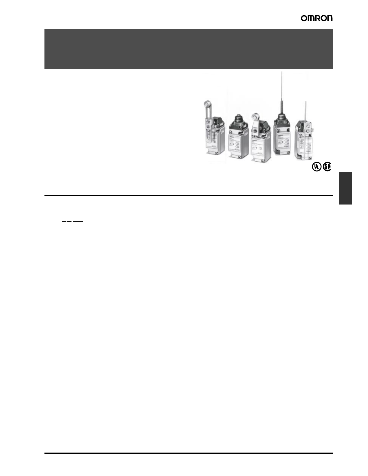
General-purpose Limit Switch
D4A-
@N
The Limit Switch with Better Seal, Shock
Resistance, and Strength
• A double seal on the head, a complete gasket cover, and other
features ensure a better seal (meets UL NEMA 3, 4, 4X, 6P, 12,
13).
• Block mounting method to reduce weight to 290 g.
• Block mounting method also reduces downtime for mainte-
nance.
• Wide standard operating temperature range:
–40°C to 100°C (standard type).
• Models with fluoro-rubber available for greater resistance to
chemicals.
• DPDT, double-break models available for complex operations.
Model Number Structure
■
Model Number Legend
1. Receptacle Box
1: 1/2-14 NPT conduit (SPDT, double-break)
2: 1/2-14 NPT conduit (DPDT, double-break)
3: G 1/2 conduit (SPDT, double-break)
4: G 1/2 conduit (DPDT, double-break)
5: M20 x 1.5 conduit (SPDT, double-break)
6: M20 x 1.5 conduit (DPDT, double-break)
2. Switch Box
1: SPDT, double-break, without indicator
3: SPDT, double-break, neon lamp
A: SPDT, double-break, LED (12 VDC)
C: SPDT, double-break, LED
(24 VDC, leakage current: 4 mA)
E: SPDT, double-break, LED
(24 VDC, leakage current: 1.3 mA)
G: SPDT, double-break, LED (48 VDC)
5: DPDT, double-break, simultaneous operation, without indi-
cator
7: DPDT, double-break, sequential operation, without indicator
(See note 1.)
9: DPDT, double-break, center neutral operation, without indi-
cator (See note 2.)
L: DPDT, double-break, simultaneous operation, neon lamp
M: DPDT, double-break, sequential operation, neon lamp
(See note 1.)
N: DPDT, double-break, center neutral operation, neon lamp
(See note 2.)
P: DPDT, double-break, simultaneous operation, LED
Q: DPDT, double-break, sequential operation, LED
(See note 1.)
R: DPDT, double-break, center neutral operation, LED
(See note 2.)
3. Head
01: Roller lever, standard
02: Roller lever, high-sensitivity
03: Roller lever, low torque
04: Roller lever, high-sensitivity, low torque
05: Roller lever, maintained
17: Roller lever, sequential operation
18: Roller lever, center neutral operation
06: Side plunger, standard
07-V: Side plunger, vertical roller
07-H: Side plunger, horizontal roller
08: Side plunger, adjustable
09: Top plunger, standard
10: Top plunger, roller
11: Top plunger, adjustable
12: Flexible rod, spring wire
14: Flexible rod, plastic rod
15: Flexible rod, cat whisker
16: Flexible rod, coil spring
Note: 1.
Use the D4A-0017N Special Head.
2.
Use the D4A-0018N Special Head.
3.
Fluoro-rubber sealed type is also available.
1 2 3
D4A-@@@@N
Page 2
F-10
General-purpose Limit Switch
D4A-
@N
Ordering Information
■
List of Models
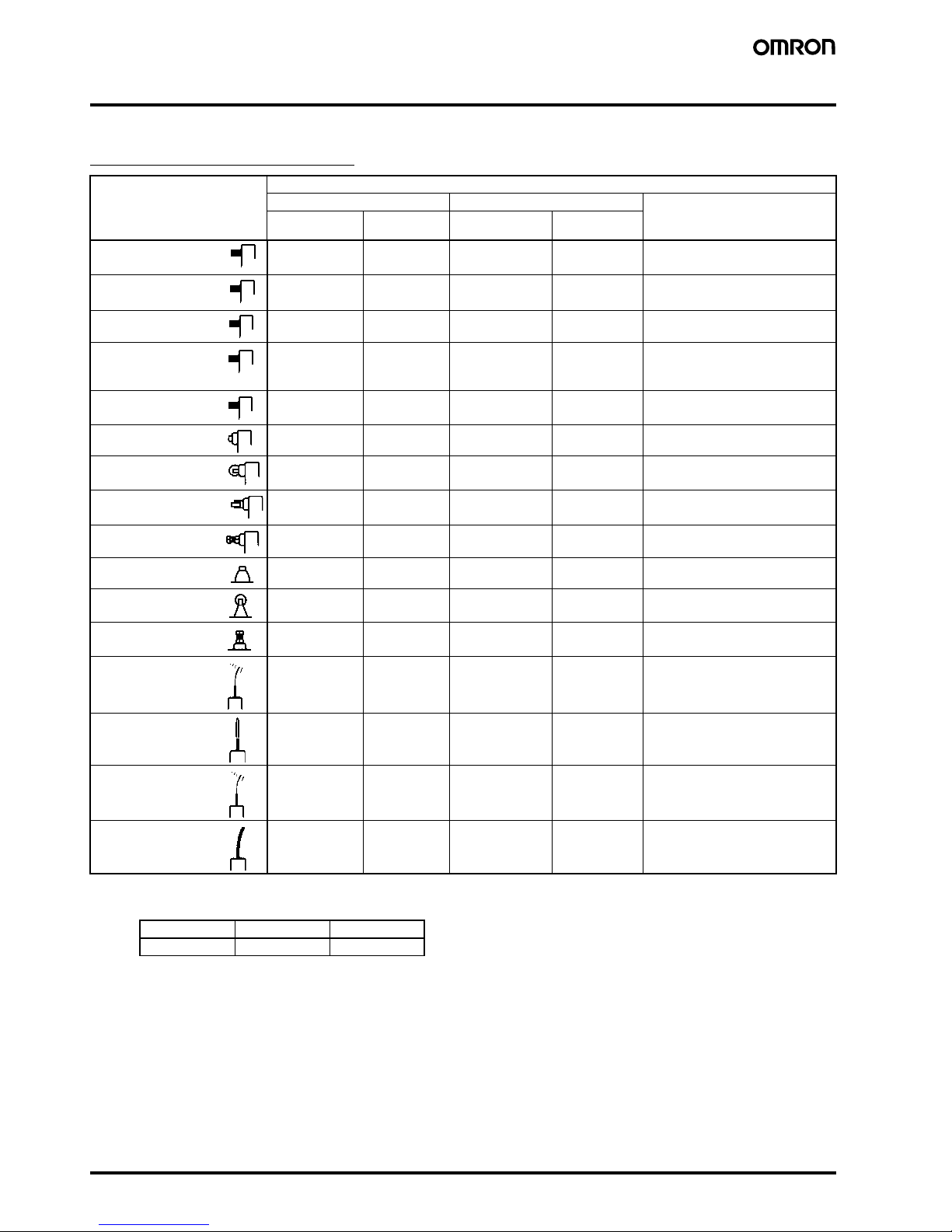
SPDT Double-break Switches
Note: 1.
The Switches listed above with an optional G1/2 or M20 x 1.5 conduit can be supplied upon request. To order, change the conduit identifier in the model number as follows:
2.
Switches with fluoro-rubber seals (with an operating temperature range of –10°C to 120°C) may be ordered by adding an “F” suffix to the
model number. (Example: D4A-3101N-F for D4A-3101N) Contact your OMRON representative for details.
3.
Switches with silicon rubber seals that have high weather-proof performance are also available and may be ordered by adding an “T”
suffix to the model number. (Example: D4A-3112N-T for D4A-3112N) Contact your OMRON representative for details.
4.
Levers for Roller Lever Switches are optionally available. Select the lever from those listed in this datasheet (refer to
Levers
on pages 28
and 29) and order.
5.
“Roller lever: maintained” refers to actuators that possess a lock mechanism for switching operations. Use a Fork Lever Lock (D4A-E@@)
as the lever.
Actuator 1/2-14NPT conduit
Without indicator With neon lamp indicator (AC) With LED indicator (DC)
Model Approved
standards
Model Approved
standards
D4A-1101N UL, CSA D4A-1301N UL, CSA D4A-1A01N, D4A-1C01N,
D4A-1E01N, D4A-1G01N
D4A-1102N UL, CSA D4A-1302N UL, CSA D4A-1A02N, D4A-1C02N,
D4A-1E02N, D4A-1G02N
D4A-1103N UL, CSA D4A-1303N UL, CSA D4A-1A03N, D4A-1C03N,
D4A-1E03N, D4A-1G03N
D4A-1104N UL, CSA D4A-1304N UL, CSA D4A-1A04N, D4A-1C04N,
D4A-1E04N, D4A-1G04N
D4A-1105N UL, CSA D4A-1305N UL, CSA D4A-1A05N, D4A-1C05N,
D4A-1E05N, D4A-1G05N
D4A-1106N UL, CSA D4A-1306N UL, CSA D4A-1A06N, D4A-1C06N,
D4A-1E06N, D4A-1G06N
D4A-1107-VN UL, CSA D4A-1307-VN UL, CSA D4A-1A07-VN, D4A-1C07-VN,
D4A-1E07-VN, D4A-1G07-VN
D4A-1107-HN UL, CSA D4A-1307-HN UL, CSA D4A-1A07-HN, D4A-1C07-HN,
D4A-1E07-HN, D4A-1G07-HN
D4A-1108N UL, CSA D4A-1308N UL, CSA D4A-1A08N, D4A-1C08N,
D4A-1E08N, D4A-1G08N
D4A-1109N UL, CSA D4A-1309N UL, CSA D4A-1A09N, D4A-1C09N,
D4A-1E09N, D4A-1G09N
D4A-1110N UL, CSA D4A-1310N UL, CSA D4A-1A10N, D4A-1C10N,
D4A-1E10N, D4A-1G10N
D4A-1111N UL, CSA D4A-1311N UL, CSA D4A-1A11N, D4A-1C11N,
D4A-1E11N, D4A-1G11N
D4A-1112N UL, CSA D4A-1312N UL, CSA D4A-1A12N, D4A-1C12N,
D4A-1E12N, D4A-1G12N
D4A-1114N UL, CSA D4A-1314N UL, CSA D4A-1A14N, D4A-1C14N,
D4A-1E14N, D4A-1G14N
D4A-1115N UL, CSA D4A-1315N UL, CSA D4A-1A15N, D4A-1C15N,
D4A-1E15N, D4A-1G15N
D4A-1116N UL, CSA D4A-1316N UL, CSA D4A-1A16N, D4A-1C16N,
D4A-1E16N, D4A-1G16N
1/2-14NPT G1/2 M20 x 1.5
D4A-1
@@@
ND4A-3
@@@
ND4A-5
@@@
N
Roller lever: standard
(See note 4.)
Roller lever: highsensitivity (See note 4.)
Roller lever: low torque
(See note 4.)
Roller lever: highsensitivity/low torque
(See note 4.)
Roller lever: maintained
(See note 4 and 5.)
Side plunger
Side-roller plunger:
vertical roller
Side-roller plunger:
horizontal roller
Side plunger:
adjustable
Top plunger
Top plunger:
roller
Top plunger:
adjustable
Flexible rod:
Spring wire
Flexible rod:
Plastic rod
Flexible rod:
Cat whisker
Flexible rod:
Coil spring
Page 3
General-purpose Limit Switch
D4A-
@N
F-11
Limit
Switches
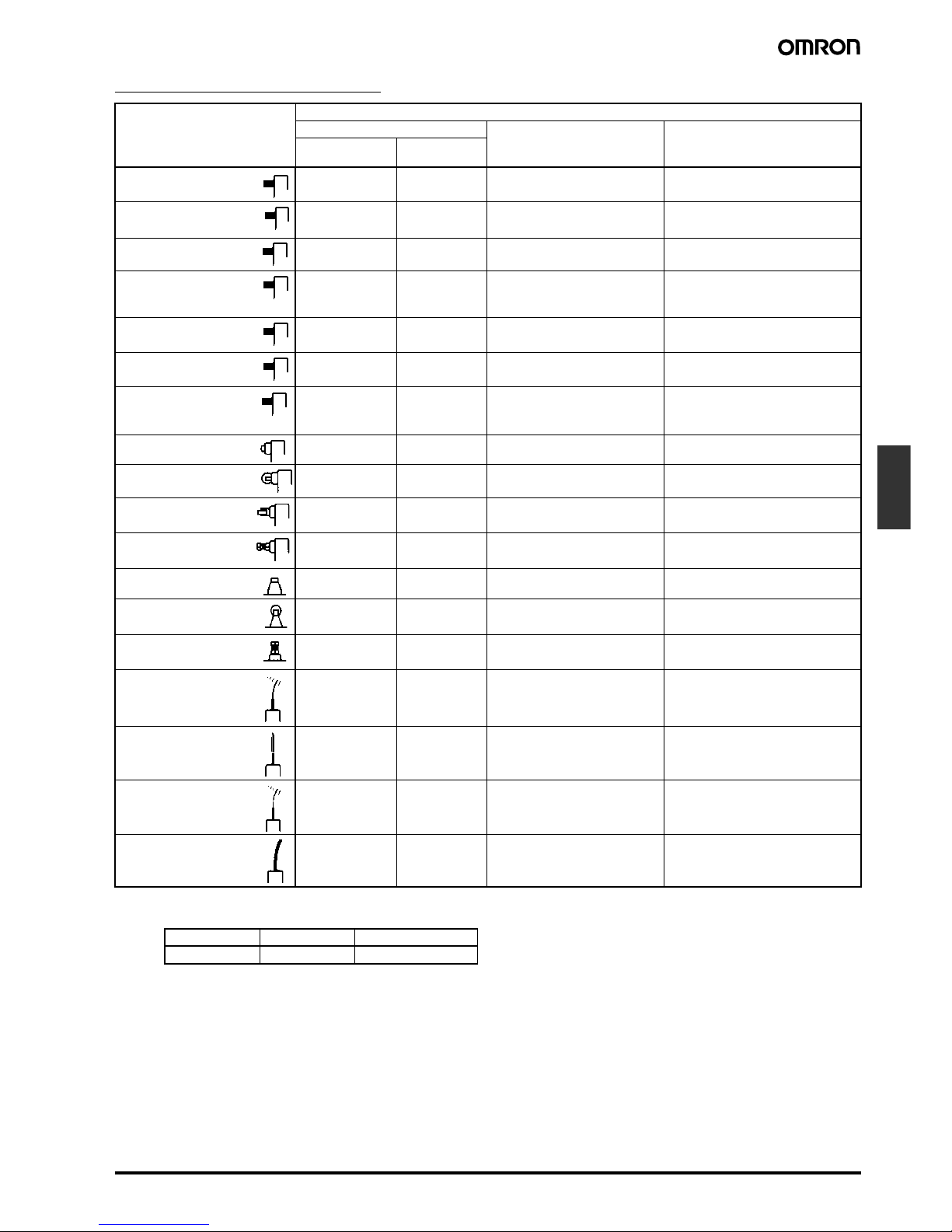
DPDT Double-break Switches
Note: 1.
The Switches listed above with an optional G1/2 or M20 x 1.5 conduit can be supplied upon request. To order, change the conduit iden-
tifier in the model number as follows:
2.
Switches with fluoro-rubber seals (with an operating temperature range of –10°C to 120°C) may be ordered by adding an “F” suffix to the
model number. (Example: D4A-3101N-F for D4A-3101N) Contact your OMRON representative for details.
3.
Levers for Roller Lever Switches are optionally available. Select the lever from those listed in this data sheet (refer to
Levers
on pages 28
and 29) and order.
4.
“Roller lever: maintained” refers to actuators that possess a lock mechanism for switching operations. Use a Fork Lever Lock (D4A-E@@)
as the lever.
Actuator 1/2-14NPT conduit
Without indicator With neon lamp indicator
(AC)
With LED indicator
(DC)
Model Approved
standards
D4A-2501N UL, CSA D4A-2L01N D4A-2P01N
D4A-2502N UL, CSA D4A-2L02N D4A-2P02N
D4A-2503N UL, CSA D4A-2L03N D4A-2P03N
D4A-2504N UL, CSA D4A-2L04N D4A-2P04N
D4A-2505N UL, CSA D4A-2L05N D4A-2P05N
D4A-2717N UL, CSA D4A-2M17N D4A-2Q17N
D4A-2918N UL, CSA D4A-2N18N D4A-2R18N
D4A-2506N UL, CSA D4A-2L06N D4A-2P06N
D4A-2507-VN UL, CSA D4A-2L07-VN D4A-2P07-VN
D4A-2507-HN UL, CSA D4A-2L07-HN D4A-2P07-HN
D4A-2508N UL, CSA D4A-2L08N D4A-2P08N
D4A-2509N UL, CSA D4A-2L09N D4A-2P09N
D4A-2510N UL, CSA D4A-2L10N D4A-2P10N
D4A-2511N UL, CSA D4A-2L11N D4A-2P11N
D4A-2512N UL, CSA D4A-2L12N D4A-2P12N
D4A-2514N UL, CSA D4A-2L14N D4A-2P14N
D4A-2515N UL, CSA D4A-2L15N D4A-2P15N
D4A-2516N UL, CSA D4A-2L16N D4A-2P16N
1/2-14NPT G 1/2 M20 x 1.5
D4A-2
@@@
ND4A-4
@@@
ND4A-6
@@@
N
Roller lever: standard
(See note 3.)
Roller lever: highsensitivity (See note 3.)
Roller lever: low
torque (See note 3.)
Roller lever: highsensitivity/low torque
(See note 3.)
Roller lever: maintained
(See note 3 and 4.)
Roller lever: sequential
operating (See note 3.)
Roller lever: center
neutral operating
(See note 3.)
Side plunger
Side-roller plunger:
vertical roller
Side-roller plunger:
horizontal roller
Side plunger:
adjustable
Top plunger
Top plunger:
roller
Top plunger:
adjustable
Flexible rod:
Spring wire
Flexible rod:
Plastic rod
Flexible rod:
Cat whisker
Flexible rod:
Coil spring
Page 4

F-12
General-purpose Limit Switch
D4A-
@N
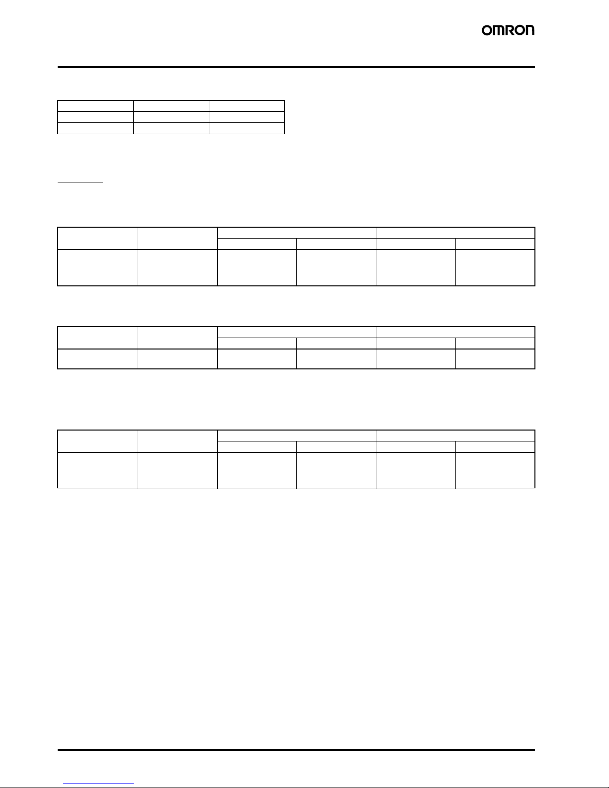
Individual Parts
Replacement of Parts
Because the D4A-@N employs block mounting construction, the
switch body, receptacle, and operating head may be ordered as a
complete assembly or individually as replacement parts.
Receptacle Box
Note: 1.
M6-screw mounting (standard mounting)
2.
10-32UNF-screw mounting (standard mounting)
Switch Box
Receptacle Switch box Head Lever
D4A-1101N D4A-1000N D4A-0100N D4A-0001N
Levers for Roller Lever Switches are optionally
available. Select the lever from those listed in
this datasheet and order (refer to Levers on
pages 20 and 21).
Type Appearance 1/2-14NPT conduit (See note 2.) G1/2 conduit (See note 1.) M20 x 1.5 (See note 1.)
Model Approved
standards
Model Approved
standards
Model Approved
standards
SPDT
doublebreak
D4A-1000N UL, CSA D4A-3000N UL, CSA D4A-5000N UL, CSA
DPDT
doublebreak
D4A-2000N UL, CSA D4A-4000N UL, CSA D4A-6000N UL, CSA
Type Appearance Without indicator With neon lamp indicator
(AC)
With LED
indicator (DC)
Model Approved
standards
Model Approved
standards
Model
SPDT
double-break
D4A-0100N UL, CSA D4A-0300N UL, CSA D4A-0A00N
D4A-0C00N
D4A-0E00N
D4A-0G00N
DPDT
double-break
Simultaneous
operation
D4A-0500N UL, CSA D4A-0L00N --- D4A-0P00N
Sequential operation
D4A-0700N UL, CSA D4A-0M00N --- D4A-0Q00N
Center neutral
operation
D4A-0900N UL, CSA D4A-0N00N --- D4A-0R00N
(Without indicator lamp)
(Without indicator lamp)
Page 5

General-purpose Limit Switch
D4A-
@N
F-13
Limit
Switches
Heads
Note: 1.
Levers for Roller Lever Switches are optionally available. Select the lever from those listed in this data sheet and order (refer to
Levers
on pages 28 and 29).
2.
The D4A-C00 adjustable roller lever is too heavy and long for these heads and it should not be used or mechanical malfunction will result.
3.
These heads cannot be used for double break operations.
Type Appearance Approved standards
Roller lever
(See note 1.)
UL, CSA
UL, CSA
Side plunger
UL, CSA
Top plunger
UL, CSA
Flexible rod
UL, CSA
Standard: D4A-0001N
High-sensitivity: D4A-0002N
Low torque: D4A-0003N (see note 2)
High-sensitivity/low torque: D4A-0004N (see note 2)
Sequential operation: D4A-0017N (see note 3)
Center neutral operation: D4A-0018N (see note 3)
Maintained: D4A-0005N
Standard:
D4A-0006N
Horizontal roller:
D4A-0007-HN
Vertical roller:
D4A-0007-VN
Side adjustable:
D4A-0008N
Standard:
D4A-0009N
Roller plunger:
D4A-0010N
Plunger adjustable:
D4A-0011N
Spring wire
D4A-0012N
Plastic rod
D4A-0014N
Cat whisker
D4A-0015N
Coil spring
D4A-0016N
Page 6
F-14
General-purpose Limit Switch
D4A-
@N
Specifications
■
Approved Standards
■
Approved Standard Ratings
UL/CSA
A600
D4A-@1@@N (SPDT, Double-break, Without Indicator)
A300
D4A-@3@@N (SPDT, Double-break, With Neon Lamp)
B600
D4A-@5@@N (DPDT, Double-break, Simultaneous Operation)
D4A-@7@@N (DPDT, Double-break, Sequential Operation)
D4A-@9@@N (DPDT, Double-break, Center Neutral Operation)
Agency Standard File No.
UL UL508 E76675
CSA CSA C22.2 No. 14 LR45746
Rated voltage Carry current Current Volt-amperes
Make Break Make Break
120 VAC
240 VAC
480 VAC
600 VAC
10 A 60 A
30 A
15 A
12 A
6 A
3 A
1.5 A
1.2 A
7,200 VA 720 VA
Rated voltage Carry current Current Volt-amperes
Make Break Make Break
120 VAC
240 VAC
10 A 60 A
30 A
6 A
3 A
7,200 VA 720 VA
Rated voltage Carry current Current Volt-amperes
Make Break Make Break
120 VAC
240 VAC
480 VAC
600 VAC
5 A 30 A
15 A
7.5 A
6.0 A
3 A
1.5 A
0.75 A
0.6 A
3,600 VA 360 VA
Page 7
General-purpose Limit Switch
D4A-
@N
F-15
Limit
Switches
■
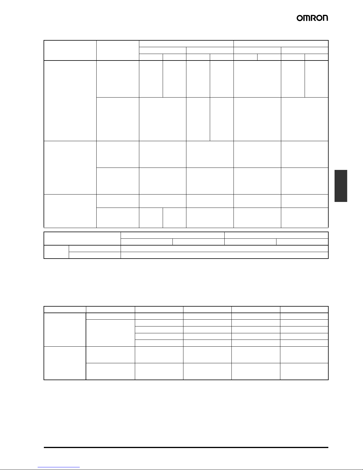
Ratings
Note: 1.
The above current ratings are for steady-state current.
2.
Inductive loads have a power factor of 0.4 min. (AC) and a time constant of 7 ms max. (DC).
3.
Lamp loads have an inrush current of 10 times the steady-state current.
4.
Motor loads have an inrush current of 6 times the steady-state current.
5.
For those with indicators, refer to the following rated voltages.
Indicators
Type Rated voltage Non-inductive load Inductive load
Resistive load Lamp load Inductive load Motor load
NC NO NC NO NC NO NC NO
SPDT double-break
(with/without
indicator)
125 VAC (See note
5.)
10 A 10 A 3 A 1.5 A 10 A 5 A 2.5 A
250 VAC (See note
5.)
10 A 10 A 2 A 1 A 10 A 3 A 1.5 A
480 VAC 10 A 10 A 1.5 A 0.8 A 3 A 1.5 A 0.8 A
600 VAC 3 A 1 A 1 A 0.5 A 1.5 A 1 A 0.5 A
8 VDC 10 A 6 A 3 A 10 A 6 A
14 VDC 10 A 6 A 3 A 10 A 6 A
30 VDC 6 A 4 A 3 A 6 A 4 A
125 VDC (See note
5.)
0.8 A 0.2 A 0.2 A 0.8 A 0.2 A
250 VDC (See note
5.)
0.4 A 0.1 A 0.1 A 0.4 A 0.1 A
DPDT double-break
(without indicator)
125 VAC 5 A 2 A 4 A 3 A
250 VAC 3 A 1 A 2 A 1.5 A
480 VAC 1.5 A 0.5 A 1 A 0.8 A
600 VAC 1 A 0.4 A 0.7 A 0.5 A
14 VDC 5 A 2 A 4 A 3 A
30 VDC 3 A 1 A 2 A 1.5 A
125 VDC 0.4 A 0.1 A 0.4 A 0.1 A
250 VDC 0.2 A 0.05 A 0.2 A 0.05 A
DPDT double-break
(with indicator)
125 VAC 5 A 2 A 4 A 3 A
250 VAC 3 A 1 A 2 A 1.5 A
12 VDC 5 A --- --- --- --24 VDC 3 A
48 VDC 1 A
Type SPDT, double-break DPDT, double-break
Without indicator With indicator Without indicator With indicator
Inrush
current
Normally closed
30 A max.
Normally open
20 A max.
Classification Indicator Model Rated voltage Carry current Internal resistance
SPDT
double-break
Neon lamp D4A-0300N 125 VAC, 250 VAC Approx. 0.47 mA 150 k
Ω
LED D4A-0A00N 12 VDC Approx. 3.2 mA 2.2 k
Ω
D4A-0C00N 24 VDC Approx. 4 mA 4.7 k
Ω
D4A-0E00N 24 VDC Approx. 1.3 mA 15 k
Ω
D4A-0G00N 48 VDC Approx. 2 mA 22 k
Ω
DPDT
double-break
Neon lamp D4A-0L00N
D4A-0M00N
D4A-0N00N
125 VAC, 250 VAC Approx. 0.28 mA 240 k
Ω
LED D4A-0P00N
D4A-0Q00N
D4A-0R00N
48 VDC Approx. 1.4 mA ---
Page 8

F-16
General-purpose Limit Switch
D4A-
@N
■
Characteristics
Note: 1.
The above figures are initial values.
2.
Excluding maintained models.
3.
The values are calculated at an operating temperature of 5°C to 35°C, and an operating humidity of 40% to 70%. Contact your OMRON
sales representative for more detailed information on other operating environments.
4.
1,500 VAC is applied to the indicator lamp type.
5.
Not including wobble levers (cat whisker, plastic rod, coil spring, and spring wire types).
5-1.
Excluding low-torque and high-sensitivity models.
5-2.
Including roller lever low-torque and high-sensitivity operating models.
5-3.
Should not cause icing.
Degree of protection
IP67
Durability (See note 3.)
Mechanical: SPDT, double-break, roller lever: 50,000,000 operations min. (See note 2.)
DPDT, double-break, roller lever: 30,000,000 operations min. (See note 2.)
Electrical: SPDT, double-break: for 125 VAC, 10 A resistive load: 1,000,000 operations min.
DPDT, double-break: for 125 VAC, 5 A resistive load: 750,000 operations min.
Operating speed
1 mm to 2 m/s (for D4A-3101N roller lever model)
Operating frequency
Mechanical: 300 operations/minute
Electrical: 30 operations/minute
Rated frequency
50/60 Hz
Insulation resistance
100 MΩ min. (at 500 VDC) between terminals of the same polarity, between current-carrying metal parts and
ground, and between each terminal and non-current-carrying metal part
Contact resistance
25 mΩ max. (initial value)
Temperature rise
50°C max.
Dielectric strength
1,000 VAC, 50/60 Hz for 1 min. between terminals of same polarity
2,200 VAC, 50/60 Hz for 1 min. between current-carrying metal parts and ground, and between each terminal
and non-current-carrying metal part (See note 4.)
Pollution degree
(operating environment)
3
Protection against electric
shock
Class I (with grounding terminal)
Vibration resistance
Malfunction: 10 to 55 Hz, 1.5-mm double amplitude (See note 5.)
Shock resistance
Destruction: 1,000 m/s
2
min.
Malfunction: SPDT, double-break, roller lever: 600 m/s
2
min. (See note 5.)
DPDT, double-break, roller lever: 300 m/s
2
min. (See note 5.)
Ambient operating humidity
95% max. (with no icing)
Weight
Approx. 290 g (for D4A-3101N roller lever model)
Type Roller lever
(See note 5-1.)
Plunger, flexible rod
(See note 5-2.)
With indicator Fluoro-rubber seal
Ambient temperature
(See note 5-3.)
–40°C to 100°C –20°C to 100°C –10°C to 80°C –10°C to 120°C
Page 9

General-purpose Limit Switch
D4A-
@N
F-17
Limit
Switches
■
Operating Characteristics
Note:
The figures in the parentheses are average values.
Roller Lever Switches
SPDT Double-break
DPDT Double-break
The figures in the parentheses are average values.
Side Plunger Switches
Top Plunger Switches
Flexible Rod Switches
Model D4A-1@01N D4A-1@02N D4A-1@03N D4A-1@04N D4A-1@05N
OF max.
0.39 N·m 0.39 N·m0.2 N·m0.2 N·m 0.39 N·m
RF min.
0.05 N·m 0.05 N·m --- --- ---
PT max.
15° (12°)7
°
(6°)15
°
(12°)7
°
(6°)65
°
(60°)
OT min.
70
°
75
°
70
°
75
°
20
°
MD max.
5° (4°)4
°
(3°)5
°
(4°)4
°
(3°)35
°
(30°)
Model D4A-2@01N D4A-2@02N D4A-2@03N D4A-2@04N D4A-2@05N D4A-2@17N D4A-2@18N
OF max.
0.39 N·m 0.39 N·m0.2 N·m 0.2 N·m0.39 N·m 0.39 N·m 0.39 N·m
RF min.
0.05 N·m 0.05 N·m --- --- --- 0.05 N·m 0.02 N·m
PT max.
15° (12°)7
°
(6°)15
°
(12°)7
°
(6°)65
°
(60°) 1-stage: 12° (10°)
2-stage: 20° (17°)
19° (15°)
OT min.
70
°
75
°
70
°
75
°
20
°
65
°
65
°
MD max.
7° (6°)5
°
(4°)7
°
(6°)5
°
(4°)35
°
(30°)6
°
(5°)5
°
(4°)
Model SPDT double-break DPDT double-break
D4A-1@06N D4A-1@07-HN D4A-1@07-VN D4A-1@08N D4A-2@06N D4A-2@07-HN D4A-2@07-VN D4A-2@08N
OF max.
19.61 N 19.61 N 19.61 N 19.61 N 19.61 N 19.61 N 19.61 N 19.61 N
RF min.
4.90 N 4.90 N 4.90 N 4.90 N 4.90 N 4.90 N 4.90 N 4.90 N
PT max.
2.4 mm 2.4 mm 2.4 mm 2.4 mm 2.4 mm 2.4 mm 2.4 mm 2.4 mm
OT min.
5.1 mm 5.1 mm 5.1 mm 5.1 mm 5.1 mm 5.1 mm 5.1 mm 5.1 mm
MD max.
0.6 mm 0.6 mm 0.6 mm 0.6 mm 1.0 mm 1.0 mm 1.0 mm 1.0 mm
OP
34±0.8 mm 44±0.8 mm 44±0.8 mm 41 to 47.5 mm 34±0.8 mm 44±0.8 mm 44±0.8 mm 41 to 47.5 mm
Model SPDT double-break DPDT double-break
D4A-1@09N D4A-1@10N D4A-1@11N D4A-2@09N D4A-2@10N D4A-2@11N
OF max.
17.65 N 17.65 N 17.65 N 17.65 N 17.65 N 17.65 N
RF min.
4.90 N 4.90 N 4.90 N 4.90 N 4.90 N 4.90 N
PT max.
1.6 mm 1.6 mm 1.6 mm 1.6 mm 1.6 mm 1.6 mm
OT min.
5.1 mm 5.1 mm 5.1 mm 5.1 mm 5.1 mm 5.1 mm
MD max.
0.4 mm 0.4 mm 0.4 mm 1.0 mm 1.0 mm 1.0 mm
OP
46±0.8 mm 56±0.8 mm 55.5 to 62 mm 46±0.8 mm 56±0.8 mm 55.5 to 62 mm
Model SPDT double-break DPDT double-break
D4A-1@12N D4A-1@14N
D4A-1@15N
D4A-1@16N D4A-2@12N D4A-2@14N
D4A-2@15N
D4A-2@16N
OF max.
0.98 N 1.47 N 0.98 N 1.47 N
PT max.
15° (5°)15
°
(5°)15
°
(5°)15
°
(5°)
Page 10

F-18
General-purpose Limit Switch
D4A-
@N
■
Contact Form (Switch Box)
SPDT Double-break Switches
Note:
Indicator setting is made before shipping so that it will light when the Limit Switch is not being operated.
DPDT Double-break Switches
Note: 1.
Use the D4A-0017N Special Head.
2.
Use the D4A-0018N Special Head.
3.
Indicator lamp setting is made before shipping so that it will light when the Limit Switch is not being operated.
Without indicator With neon lamp indicator (See note.) With LED indicator (See note.)
D4A-0100N
4
(NO)
1
(NC)
3
(NO)
2
(NC)
D4A-0300N
NO-ON
NC-ON
Neon lamp
Resistor
Internal circuit
Lamp
unit
Lamp
unit
4
(NO)
1
(NC)
3
(NO)
2
(NC)
Resistor
LED
Bridge rectifier
Internal circuit
NO-ON
NC-ON
Lamp
unit
Lamp
unit
4
(NO)
1
(NC)
3
(NO)
2
(NC)
D4A-0A00N, D4A-0C00N,
D4A-0E00N, D4A-0G00N
Type Simultaneous operation Sequential operation Center neutral operation Internal circuit of indicator
Without
indicator
---
With neon
lamp
indicator
(See note 3.)
With LED
indicator
(See note 3.)
4
1
8
5
3
2
7
6
D4A-0500N
4
1
8
5
3
2
7
6
D4A-0700N
(See note 1.)
4
1
8
5
3
2
7
6
D4A-0900N
(See note 2.)
4
1
8
5
3
2
7
6
D4A-0L00N
Lamp
unit
Lamp
unit
Lamp
unit
Lamp
unit
4
1
8
5
3
2
7
6
D4A-0M00N
Lamp
unit
Lamp
unit
Lamp
unit
Lamp
unit
4
1
8
5
3
2
7
6
D4A-0N00N
Lamp
unit
Lamp
unit
Lamp
unit
Lamp
unit
Neon lamp
Resistor
4
1
8
5
3
2
7
6
D4A-0P00N
Lamp
unit
Lamp
unit
Lamp
unit
Lamp
unit
4
1
8
5
3
2
7
6
D4A-0Q00N
Lamp
unit
Lamp
unit
Lamp
unit
Lamp
unit
4
1
8
5
3
2
7
6
D4A-0R00N
Lamp
unit
Lamp
unit
Lamp
unit
Lamp
unit
LED
Bridge rectifier
Constant
current
diode
Page 11

General-purpose Limit Switch
D4A-
@N
F-19
Limit
Switches
■
Contacts
The D4A-@N saves installation space, simplifies wiring methods, and lowers operation costs because only a single D4A-@N is required for the
control of the speeds of a factory machine or selection of CW or CCW rotation of a motor, for which two conventional limit switches are required.
Engineering Data
■
Electrical Durability (SPDT Double-bread)
Pole1
Pole2
Pole1
Pole2
Pole1
Pole2
Pole1
Pole2
Pole 1
Pole 2
Simultaneous Operation Sequential Operating
Use the D4A-0017N head.
Pole 1 operates first and pole 2 operates second.
Center Neutral Operating
Use the D4A-0018N head.
Pole 1 operates on CW and pole 2 operates CCW.
Free position (FP) Operating Pole 1 operates first Pole 2 operates second
D4A-@ center neutral type
Pole1
Pole2
Pole1
Pole2
This head is compatible with a SPDT type
head.
Free position
(FP)
Pole 1 and pole 2 are actuated simultaneously.
Operates either CW, CCW, or both.
Pole 2 operates
on CCW
Free position
(FP)
Pole 1 operates
on CW
Note: The contact configuration of the center neutral operating
model is different from that of any other D4A-@ Switch.
Pole 2 operates
on CCW
Free position
(FP)
Pole 1 operates
on CW
125 VAC
250 VAC
480 VAC
125 VAC
250 VAC
480 VAC
(Ambient temperature: 5°C to 35°C; ambient humidity: 40% to 70%)
Switching current (A)
Durability (x 10
4
operations)
Durability (x 10
4
operations)
Switching current (A)
Operating frequencies:
30 operations/min,
cosφ = 1
Operating frequencies:
30 operations/min,
cosφ = 0.4
Page 12

F-20
General-purpose Limit Switch
D4A-
@N
Electrical Durability (DPDT Double-break)
Nomenclature
DPDT Double-break
Note: 1.
NBR is used in rubber components.
2.
Fluoro-rubber sealed types use fluoro-rubber.
125 VAC
250 VAC
480 VAC
125 VAC
250 VAC
480 VAC
Durability (x 10
4
operations)
Durability (x 10
4
operations)
Switching current (A) Switching current (A)
Operating frequencies:
30 operations/min,
cosφ = 1
Operating frequencies:
30 operations/min,
cosφ = 0.4
Head
Operating Position Mark
(arrow)
Bearings
Receptacle
Conduit Opening
Roller
The roller actuator is made of hardened
stainless steel and excels in resistance to
wear.
Lever
With the Roller Lever Switch, the lever can be
installed anywhere in a 360° range (180° if the
lever is reversed and attached to the shaft).
Oil Seal
Improved sealing property is ensured with a
double-seal construction (a oil seal plus an
X-ring seal).
Switch Box
Boasts long life expectancy (50 million mechanical
operations or more with the 2-pole Double-break
Switches and 30 million mechanical operations or
more with the DPDT Double-break Switches).
Ground Terminal Screw
A ground terminal is provided to enhance safety.
Switch Box Screw
Sealed Gasket
With the Roller Lever and Side Plunger Switches, the
direction of the switch head can be varied to any of the four
directions by loosing the roller lever switch screws at the
four corners of the head.
The Roller Lever Switch
employs a system which
allows selection of the
operation of only one side
(left or right) or both sides
without use of any tools.
The copper-alloy bearings ensure long life expectancy.
The plug-in type receptacle provides adequate
space for wiring.
G 1/2 conduit threads featuring high sealing
property are used. (Consult your OMRON
representative for details on SC connectors).
A terminal box with 1/2-14NPT conduit threads
is also available on request.
The employed full-cover method
prevents the gasket from direct
exposure to oil or water spray.
A Phillips screw is used to secure the switch
housing for ease of use, and features a measure to prevent the screw from coming off.
Page 13

General-purpose Limit Switch
D4A-
@N
F-21
Limit
Switches
Easy-maintenance Block Mounting
Block mounting makes it possible to easily assemble or disassemble
the head, switch body, and receptacle of the D4A-@N by tightening or
loosening the attached screws.
Installation
■
Operation
Changing the Operating Direction
The head of the side rotary type can be converted in seconds to CW,
CCW, or both-way operation. Follow the procedures on the right
hand side for conversion (not applicable to the Maintained, Sequential Operating, Center Neutral Operating Switches).
Operating Part (Rear of Head)
Procedures
1.
Dismount the head by loosening the four screws that secure it.
2.
Turn over the head to set the desired operation (CW, CCW, or
both). The desired side can be selected by setting the mode
selector knob shown in the figure. This knob is factory set to the
“CW+CCW” (both-way operation) position.
3.
When set to the CW position, the head rotates in clockwise direction.
When set to the CCW position, the head rotates in counterclockwise direction.
In either case, be sure to accurately align the arrow mark to the
setting position.
Actuator
Head
Receptacle
Switch box
Operating position
arrow marks
Page 14

F-22
General-purpose Limit Switch
D4A-
@N
Head and Lever Positions
The operating head can be positioned and locked in any of four 90° positions and a lever can lock in any position through 360° around the shaft of
the Limit Switch. Furthermore, the lever can be reversed and attached to the shaft (refer to the figures below on the right hand side). Therefore the
roller is compatible with a wide movement range of a dog. A Fork Lever Lock can be used with maintained models (D4A-0005N) only.
Lighting Mode Selection of Indicators
The lighting mode of the operation indicator can be changed easily between two modes: lighting when the Switch is operating and lighting when
the Switch is not operating.
Loosen the screw
to adjust the
length of the rod.
Loosen the bolt to
adjust the length
of the lever.
Adjustable
between 33
and 91 mm
D4A-E00 D4A-E10
D4A-E20 D4A-E30
Four, M4 x 12
Remove the head from the Switch by
loosening the screws (the screws can be
loosened but not removed from the
head).
The operating head can be
positioned and locked in
any of four 90° positions.
The lever can lock in any position through 360° around
the shaft. The lever can be reversed and attached to the
shaft, in which case the switching operation should complete in a range of 0° to 180°.
By loosening the Allen-head bolt on an adjustable roller lever
or rod lever, the length of the lever can be adjusted.
D4A-C00
D4A-D00
180° operating
position
360°
operating
position
There are four kinds of fork lever locks. The position of each
roller is different. It is possible to use D4A-E00 through
D4A-E30 levers instead, if they are reversed before attaching.
They can be used with D4A-@@05N models only.
43
1
2
43
1
2
Load
NO
NC
NO
NC
Power supply
Load
Power supply
Lights When Not Operating Lights When Operating
Lamp
unit
Lamp
unit
Built-in
switch
Note: 1. The lamp is lit when the actuator is at the free position.
The lamp will be off when the contacts of the Limit
Switch have been actuated and snapped to each other
at the operating position.
2. The lamp is lit when the contacts have been released
and snapped only from the operating position.
Built-in
switch
(See note 1.) (See note 2.)
Page 15

General-purpose Limit Switch
D4A-
@N
F-23
Limit
Switches
Change the lighting mode as follows:
Lever Position
■
Nameplate
■
Compatibility with D4A-
@
The D4A-@N is compatible with the D4A-@ when the following accessories are attached to the D4A-@N.
Note:
The D4A-@N without the above accessories is not compatible with the D4A-@.
Push the claw securing
the lamp section to the
right (do not push
strongly).
Remove the
lamp section.
Mount the lamp section
so that legend "NC-ON"
or "NO-ON" will appear
in the display window.
Note:
In either case, the lamp will
not light when the load is ON.
86.9 to 92.4
73 to 78.5
38.9 to 44.4
67 to 72.5
44.9 to 50.4
59 to 64.5
52.9 to 58.4
D4A-A00 D4A-A10 D4A-A20 D4A-A30
25 to
30.5
The type of switch box is printed.
(The type is also indicated on the
head and receptable.)
The whole switch model without
lever is printed.
D4A-@
Receptacle box
D4A-@N
Switch box
D4A-@N
Head
Page 16

F-24
General-purpose Limit Switch
D4A-
@N
Dimensions
Note: 1.
All units are in millimeters unless otherwise indicated.
2.
Insert the model number code in @ for the switch body.
3.
Unless otherwise specified, a tolerance of ±0.4 mm applies to all dimensions.
Roller Lever Switches
Note:
Levers of the side rotary type are optionally available.
5.2
6
0.8
70.5
19.1
38.1
42
62
47.5
21
75.5
16.5
28
44
59.5±0.2
2.6R
2.6R
29.4±0.2
19
24.5
34
70.5
5.2
42
0.8
6
62.5
48
21
16.5
44
75.5
2.6R
2.6R
29.4±0.2
59.5±0.2
28
29.5
29.5
7.25 dia.
7.25 dia.
Standard
D4A-1@01N, D4A-2@01N
High-sensitivity
D4A-1@02N, D4A-2@02N
Center Neutral Operating
D4A-2@18N
Low Torque
D4A-1@03N, D4A-2@03N
High-sensitivity/Low Torque
D4A-1@04N, D4A-2@04N
Sequential Operation
D4A-2@17N
Maintained
D4A-1@05N, D4A-2@05N
Four, M4 (length: 12)
screws for head
0
5.2
+0.2
dia.
mounting holes
Two, M5 (length: 20)
screws for box
1/2-14NPT
conduit
Two, No.10-32UNF
(depth: 10) screws for
back-mounting
Four, M4 (length: 12)
screws for head
0
5.2
+0.2
dia.
mounting holes
Two, M5 (length: 20)
screws for box
1/2-14NPT
conduit
Two, No.10-32UNF
(depth: 10) screws for
back-mounting
Page 17

General-purpose Limit Switch
D4A-
@N
F-25
Limit
Switches
Side Plunger Switches
6
5.2
44
16.5
28
29.5
75.5
42
19
70.5
0.8
21
OPPT
29.4±0.2
59.5±0.2
2.6R
2.6R
21.5
31.1
5.2
16.5
28
29.5
44
42
21.5
19
31.1
70.5
75.5
6
0.8
21
OP
PT
29.4±0.2
59.5±0.2
2.6R
2.6R
42
5.2
6
0.8
21.5
19
31.1
70.5
75.5
21
16.5
28
29.5
44
OP
PT
59.5±0.2
2.6R
2.6R
29.4±0.2
70.5
19
6
0.8
21.5
31.1
5.2
42
75.5
16.5
28
29.5
44
21
59.5±0.2
2.6R
2.6R
OP
PT
29.4±0.2
10 dia.
Standard
D4A-1@06N, D4A-2@06N
Horizontal Roller
D4A-1@07-HN, D4A-2@07-HN
Vertical Roller
D4A-1@07-VN, D4A-2@07-VN
Adjustable
D4A-1@08N, D4A-2@08N
Four, M4 (length: 12)
screws for head
Stainless
steel
plunger
0
5.2
+0.2
dia.
mounting holes
Two, M5 (length: 20)
screws for box
1/2-14NPT
conduit
Two, No.10-32UNF
(depth: 10) screws for
back-mounting
Four, M4 (length: 12)
screws for head
11 dia.x 5 stainless
steel roller
0
5.2
+0.2
dia.
mounting holes
Two, M5 (length: 20)
screws for box
1/2-14NPT
conduit
Two, No.10-32UNF
(depth: 10) screws
for back-mounting
Four, M4 (length: 12)
screws for head
11 dia.x 5 stainless
steel roller
0
5.2
+0.2
dia.
mounting holes
Two, M5 (length: 20)
screws for box
1/2-14NPT
conduit
Two, No.10-32UNF
(depth: 10) screws for
back-mounting
Four, M4 (length: 12)
screws for head
M5 x 0.8 (length: 14
Allen-head bolt
0
5.2
+0.2
dia.
mounting holes
Two, M5 (length: 20)
screws for box
1/2-14NPT
conduit
Two, No.10-32UNF
(depth: 10) screws for
back-mounting
Page 18

F-26
General-purpose Limit Switch
D4A-
@N
Top Plunger Switches
6
42
5.2
70.5
27
0.8
75.5
16.5
28
29.5
44
21
OP
PT
2.6R
2.6R
29.4±0.2
59.5±0.2
6
42
5.2
70.5
27
0.8
16.5
28
29.5
44
21
75.5
2.6R
OP
PT
2.6R
29.4±0.2
59.5±0.2
6
42
5.2
21
75.5
16.5
28
29.5
44
70.5
27
OP
PT
2.6R
2.6R
29.4±0.2
59.5±0.2
0.8
M5 x 0.8 (length:14) Allen-head bolt
11 dia. x 5 stainless steel roller
Stainless steel plunger
10 dia.
Standard
D4A-1@09N, D4A-2@09N
Roller Plunger
D4A-1@10N, D4A-2@10N
Adjustable
D4A-1@11N, D4A-2@11N
Four, M4 (length: 12)
screws for head
0
5.2
+0.2
dia.
mounting holes
Two, M5 (length: 20)
screws for box
1/2-14NPT
conduit
Two, No.10-32UNF
(depth: 10) screws for
back-mounting
Four, M4 (length: 12)
screws for head
0
5.2
+0.2
dia.
mounting holes
Two, M5 (length: 20)
screws for box
1/2-14NPT
conduit
Two, No.10-32UNF
(depth: 10) screws for
back-mounting
Four, M4 (length: 12)
screws for head
0
5.2
+0.2
dia.
mounting holes
Two, M5 (length: 20)
screws for box
1/2-14NPT
conduit
Two, No.10-32UNF
(depth: 10) screws for
back-mounting
Page 19

General-purpose Limit Switch
D4A-
@N
F-27
Limit
Switches
Flexible Rod Switches
(124)
27
0.8
6
42
5.2
93.5
170.5
70.5
16.5
28
29.5
44
75.5
21
PT
2.6R
2.6R
29.4±0.2
59.5±0.2
5.2
42
6
0.8
27
70.5
(106.5)
150
88.5
44
29.5
28
16.5
75.5
21
PT
2.6R
2.6R
29.4±0.2
59.5±0.2
5.2
42
6
0.8
88
27
70.5
(287)
44
29.5
28
16.5
75.5
PT
2.6R
2.6R
29.4±0.2
59.5±0.2
21
330
1.4 dia.
Stainless steel wire rod
(see note 1)
(see note 2)
Plastic rod
7 dia.
(see note 1)
(see note 2)
Stainless steel wire rod
8 dia. max.
1.8 dia.
(see note 1)
(see note 2)
Note: 1. The stainless rod can be operated from any direction except the axial direction (i.e., from the top).
2. The optimum operating range of the stainless rod is within 1/3 of the entire length from the top end.
Spring Wire
D4A-1@12N, D4A-2@12N
Plastic Rod
D4A-1@14N, D4A-2@14N
Cat Whisker
D4A-1@15N, D4A-2@15N
Four, M4 (length: 12)
screws for head
0
5.2
+0.2
dia.
mounting
holes
Two, M5 (length: 20)
screws for box
1/2-14NPT
conduit
Two, No.10-32UNF
(depth: 10) screws for
back-mounting
Four, M4 (length: 12)
screws for head
0
5.2
+0.2
dia.
mounting holes
Two, M5 (length: 20)
screws for box
1/2-14NPT
conduit
Two, No.10-32UNF
(depth: 10) screws for
back-mounting
Four, M4 (length: 12)
screws for head
0
5.2
+0.2
dia.
mounting
holes
Two, M5 (length: 20)
screws for box
1/2-14NPT
conduit
Two, No.10-32UNF
(depth: 10) screws for
back-mounting
Page 20

F-28
General-purpose Limit Switch
D4A-
@N
Levers (for Roller Lever Switches)
Note:
No D4A-0003N or D4A-0004N head should be used with the adjustable roller lever or mechanical malfunctioning could result because the
total weight of the adjustable roller lever is comparatively large. Use a standard-load head (D4A-0001N or D4A-0002N) instead.
27
0.8
6
42
5.2
70.5
16.5
28
29.5
44
75.5
21
150
(106.5)
PT
2.6R
2.6R
29.4±0.2
59.5±0.2
6.5 dia.
Stainless steel coil spring
(see note 1)
(see note 2)
Note: 1. The stainless rod can be operated from any direction except the axial direction (i.e., from the top).
2. The optimum operating range of the stainless rod is within 1/3 of the entire length from the top end.
Coil Spring
D4A-1@16N, D4A-2@16N
Four, M4 (length: 12)
screws for head
0
5.2
+0.2
dia.
mounting holes
Two, M5 (length: 20)
screws for box
1/2-14NPT
conduit
Two, No.10-32UNF
(depth: 10) screws for
back-mounting
7.9
38.1
18
39.4
7.9
38.1
18
916.5
19.5
38.1
18
9
7.9
11.5
7.9
38.1
18
9
21
15
33.7
18
9
9
M5 Allen bolt
19.1 dia.
7.3 dia.
M5 Allen bolt
19.1 dia.
7.3 dia.
M5 Allen bolt
19.1 dia.
7.3 dia.
M5 Allen bolt
19.1 dia.
7.3 dia.
M5 Allen bolt
17.5 dia.
7.3 dia.
Note: Stainless sintered roller
(see note)
Note: Stainless sintered roller
Roller Lever
D4A-A00
Roller Lever
D4A-A10
Roller Lever
D4A-A20
Roller Lever
D4A-A30
Roller Lever
D4A-B06
Stainless
sintered
roller
Stainless
sintered
roller
Stainless
sintered
roller
(see
note)
Page 21

General-purpose Limit Switch
D4A-
@N
F-29
Limit
Switches
Note:
A Fork Lever Lock can be used with D4A-@@05N models only.
90°
17
38.1
(2)
3.6
7.9
38.1
9
90°
17
(2)
7.9
3.6
38.1
9
38.1
10.5
160
20
13
7.5
21.2
4.5
113
13
18
21.2
2.5
4.5
147.9
M5 Allen bolt
19.1 dia.
7.3 dia.
19.1 dia.
7.3 dia.
M5 Allen bolt
3 dia.
7.3 dia.
Stainless rod
M5 Allen bolt
6.4 graduation
19.1 dia.
7.3 dia.
M5 Allen bolt
Adjustable Roller Lever
D4A-C00
Adjustable Rod Lever
D4A-D00
Fork Lever Lock
D4A-E30
Fork Lever Lock
D4A-E20
33 to 91
(adjustable)
Stainless
sintered
roller
150 max.
(adjustable)
Stainless
sintered
roller
Stainless
sintered
roller
Stainless
sintered
roller
Stainless sintered
roller
(See note.)
(See note.)
90°
38.1
(2)
3.6
7.9
9
6.2
38.1
26
22
26
38.1
(2)
3.6
7.9
9
90°
22
6.2
38.1
M5 Allen bolt
19.1 dia.
7.3 dia.
M5 Allen bolt
19.1 dia.
7.3 dia.
Fork Lever Lock
D4A-E10
Fork Lever Lock
D4A-E00
Stainless
sintered
roller
Stainless
sintered
roller
Stainless
sintered
roller
Stainless
sintered
roller
(See note.)
(See note.)
M5 Allen bolt
M5 Allen bolt
Nylon
7.3 dia.
25 max.
Nylon Loop Lever
D4A-F00
Page 22

F-30
General-purpose Limit Switch
D4A-
@N
Precautions
■
Correct Use
Mounting
Tightening Torque
To maintain the high sealing capability of the Limit Switch, tighten the
screws for the head and switch body with the following torques:
Head (four 12-mm M4 screws): 1.2 to 1.4 N·m
Switch body (two 20-mm M5 screws): 2.4 to 2.7 N·m
Solderless Terminals
The D4A-@N with DPDT double-break incorporates solderless terminals.
Operation
The operating methods, cam and dog shapes, operating frequency,
and overtravel (OT) have a significant effect on the service life and
accuracy of the Limit Switch. The shape of the cam should be as
smooth as possible.
A marginal overtravel (OT) value should be set. The ideal value is the
rated OT value x 0.7.
The actuator should not be remodeled to change the operating position.
Connectors
To satisfy IP67, apply sealing tape to the connector conduit.
Appropriate outer diameter of cables is 5.5 to 14 dia.
Use OMRON’s SC-@M Series.
Tighten the Connectors to a torque of 1.8 to 2.2 N·m.
Maintenance and Repair
The user must not maintain or repair equipment incorporating any
D4A-N model. Contact the manufacturer of the equipment for any
maintenance or repairs required.
Tightening Torque
A loose screw may cause malfunctions. Be sure to tighten each
screw to the proper tightening torque as shown in the table.
Note:
When using M5 Allen-head bolts, particularly when the head direction has been changed, check the torque of each screw and
make sure that the screws are free of foreign substances, and
that each screw is tightened to the proper torque.
Model 1/2-14NPT Conduit
D4A-1
@@@
N
D4A-2
@@@
N
Front Mounting
Rear Mounting
(Rear View)
59.5±0.15
29.4±0.15
0
Two, 5.2
+0.2
dia. holes
or M5 tapped holes
59.5±0.15
29.4±0.15
0
Two, 6.2
+0.2
dia. holes
(Recommended mounting screws: M6.
Switch Box depth: 10.)
No. Type Appropriate tightening
torque
1 Terminal screws (M3.5 screws)
(including grounding terminals)
0.78 to 0.88 N·m
2 Head mounting screws 1.18 to 1.37 N·m
3 Switch and box mounting
screws
2.35 to 2.75 N·m
4 Body mounting screws
(See note.)
4.90 to 5.88 N·m
5 Connectors 1.77 to 2.16 N·m
6 Actuator mounting screws 2.45 to 2.65 N·m
In the interest of product improvement, specifications are subject to change without notice.
ALL DIMENSIONS SHOWN ARE IN MILLIMETERS.
To convert millimeters into inches, multiply by 0.03937. To convert grams into ounces, multiply by 0.03527.
Cat. No. C092-E1-03
 Loading...