

Page 1
D
2
H
W
D2HW
D2HW -
@@@@@@@
1. Mounting Structure
A : Without posts (base-mounting)
BR : Long post on right
BL : Long post on left
C : M3-screw mounting models
ER : Short post on right
EL : Short post on left
2. Raitings
2 : 5 VDC 1mA to 12 VDC 2A
3. Actuator
0 : Pin plunger
1 : Hinge lever
2 : Long hinge lever
3 : Simulated roller lever
4 : Hinge roller lever
5 : Straight leaf lever
6 : Leaf lever
7 : Simulated roller leaf lever
8 : Long leaf lever
4. Contact form
1 : SPDT
2 : SPST-NC (Molded lead wire models only)
3 : SPST-NO (Molded lead wire models only)
5. Terminals
D, DS : PCB terminals (Straight)
DR, DRS : PCB Terminals (Right-angled)
DL, DLS : PCB Terminals (Left-angled)
H, HS : Solder terminals
M, MS : Molded lead wires downwards
MR, MRS : Molded lead wires on right-side
ML, MLS : Molded lead wires on left-side
Note. UL/CSA approved versions are available.
In this case, a "S" will be added to the end of the model number.
The Lead wire is a UL approved wire (AWG24, UL1007).
6. Special Specification
7. Special Industry Specification
1234 --567
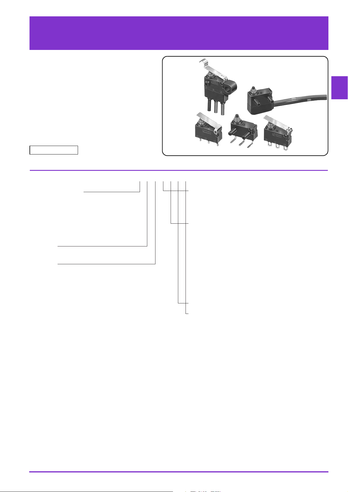
Sealed Ultra Subminiature Basic Switch
Smallest sealed snap-action
switch in the industry with a
very long stroke for reliable
ON/OFF action
● The case dimensions are 78% of conventional
models, contributing to down-sizing of
mechanical modules.
● Extra-long stroke even without levers.
(OT reference value: 1.4 mm).
● Made of environmentally-friendly materials.
All models are lead-free, including molded lead
wire models.
RoHS Compliant
Model Number Legend
1
Page 2
D2HW Sealed Ultra Subminiature Basic Switch
D
2
H
W
List of Models
●PCB-mounted Models
Actuator Terminals Contact form
Pin plunger
Hinge lever
Long hinge
lever
Simulated roller
hinge lever
For PCB
Straight
Angled
Straight
Angled
Straight
Angled
Straight
Angled
List of Models
SPDT
Long post on right
--
D2HW-BR201DR D2HW-ER201DR
--
D2HW-BR211DR D2HW-ER211DR
--
D2HW-BR221DR D2HW-ER221DR
--
D2HW-BR231DR D2HW-ER231DR
Short post
on right
List of Models
Actuator Terminals Contact form
Pin plunger
Hinge lever
Long hinge
lever
Simulated roller
hinge lever
Note1. Angled terminals and posts are the same direction.
Note2. "S" is added to the end of the model number for the UL/CSA-approved version Consult your OMRON sales representative for details.
For PCB
Straight
Angled
Straight
Angled
Straight
Angled
Straight
Angled
SPDT
Long post on left
- - D2HW-A201D
D2HW-BL201DL D2HW-EL201DL -
- - D2HW-A211D
D2HW-BL211DL D2HW-EL211DL -
- - D2HW-A221D
D2HW-BL221DL D2HW-EL221DL -
- - D2HW-A231D
D2HW-BL231DL D2HW-EL231DL -
Short post
on left
Without posts
2
Page 3
D2HW Sealed Ultra Subminiature Basic Switch
D
2
H
W
●Models with Solder Terminals or Molded Lead Wires
List of Models
Actuator Terminals Contact form
Pin plunger
Hinge lever
Long hinge lever
Simulated roller
hinge lever
Hinge roller
lever
Straight leaf
lever
Leaf lever
Simulated roller
leaf lever
Long leaf lever
Note1. The length of standard lead wires (AVSS 0.5) for molded lead wire models shown above is 30 cm.
Note2. "S" is added to the end of the model number for the UL/CSA-approved version The lead wire models are UL approved wires (AWG24, UL1007).
Consult your OMRON sales representative for details.
Solder SPDT D2HW-BR201H D2HW-ER201H
Downwards
Molded
lead wires
Solder SPDT D2HW-BR211H D2HW-ER211H
Molded
lead wires
Solder SPDT D2HW-BR221H D2HW-ER221H
Molded
lead wires
Solder SPDT D2HW-BR231H D2HW-ER231H
Molded
lead wires
Solder SPDT D2HW-BR241H D2HW-ER241H
Molded
lead wires
Solder SPDT D2HW-BR251H D2HW-ER251H
Molded
lead wires
Solder SPDT D2HW-BR261H D2HW-ER261H
Molded
lead wires
Solder SPDT D2HW-BR271H D2HW-ER271H
Molded
lead wires
Solder SPDT D2HW-BR281H D2HW-ER281H
Molded
lead wires
Right-side
Left-side
Downwards
Right-side
Left-side
Downwards
Right-side
Left-side
Downwards
Right-side
Left-side
Downwards
Right-side
Left-side
Downwards
Right-side
Left-side
Downwards
Right-side
Left-side
Downwards
Right-side
Left-side
Downwards
Right-side
Left-side
SPDT D2HW-BR201M D2HW-ER201M
SPST-NC D2HW-BR202M D2HW-ER202M
SPST-NO D2HW-BR203M D2HW-ER203M
SPST-NC D2HW-BR202MR D2HW-ER202MR
SPST-NO D2HW-BR203MR D2HW-ER203MR
SPST-NC D2HW-BR202ML D2HW-ER202ML
SPST-NO D2HW-BR203ML D2HW-ER203ML
SPDT D2HW-BR211M D2HW-ER211M
SPST-NC D2HW-BR212M D2HW-ER212M
SPST-NO D2HW-BR213M D2HW-ER213M
SPST-NC D2HW-BR212MR D2HW-ER212MR
SPST-NO D2HW-BR213MR D2HW-ER213MR
SPST-NC D2HW-BR212ML D2HW-ER212ML
SPST-NO D2HW-BR213ML D2HW-ER213ML
SPDT D2HW-BR221M D2HW-ER221M
SPST-NC D2HW-BR222M D2HW-ER222M
SPST-NO D2HW-BR223M D2HW-ER223M
SPST-NC D2HW-BR222MR D2HW-ER222MR
SPST-NO D2HW-BR223MR D2HW-ER223MR
SPST-NC D2HW-BR222ML D2HW-ER222ML
SPST-NO D2HW-BR223ML D2HW-ER223ML
SPDT D2HW-BR231M D2HW-ER231M
SPST-NC D2HW-BR232M D2HW-ER232M
SPST-NO D2HW-BR233M D2HW-ER233M
SPST-NC D2HW-BR232MR D2HW-ER232MR
SPST-NO D2HW-BR233MR D2HW-ER233MR
SPST-NC D2HW-BR232ML D2HW-ER232ML
SPST-NO D2HW-BR233ML D2HW-ER233ML
SPDT D2HW-BR241M D2HW-ER241M
SPST-NC D2HW-BR242M D2HW-ER242M
SPST-NO D2HW-BR243M D2HW-ER243M
SPST-NC D2HW-BR242MR D2HW-ER242MR
SPST-NO D2HW-BR243MR D2HW-ER243MR
SPST-NC D2HW-BR242ML D2HW-ER242ML
SPST-NO D2HW-BR243ML D2HW-ER243ML
SPDT D2HW-BR251M D2HW-ER251M
SPST-NC D2HW-BR252M D2HW-ER252M
SPST-NO D2HW-BR253M D2HW-ER253M
SPST-NC D2HW-BR252MR D2HW-ER252MR
SPST-NO D2HW-BR253MR D2HW-ER253MR
SPST-NC D2HW-BR252ML D2HW-ER252ML
SPST-NO D2HW-BR253ML D2HW-ER253ML
SPDT D2HW-BR261M D2HW-ER261M
SPST-NC D2HW-BR262M D2HW-ER262M
SPST-NO D2HW-BR263M D2HW-ER263M
SPST-NC D2HW-BR262MR D2HW-ER262MR
SPST-NO D2HW-BR263MR D2HW-ER263MR
SPST-NC D2HW-BR262ML D2HW-ER262ML
SPST-NO D2HW-BR263ML D2HW-ER263ML
SPDT D2HW-BR271M D2HW-ER271M
SPST-NC D2HW-BR272M D2HW-ER272M
SPST-NO D2HW-BR273M D2HW-ER273M
SPST-NC D2HW-BR272MR D2HW-ER272MR
SPST-NO D2HW-BR273MR D2HW-ER273MR
SPST-NC D2HW-BR272ML D2HW-ER272ML
SPST-NO D2HW-BR273ML D2HW-ER273ML
SPDT D2HW-BR281M D2HW-ER281M
SPST-NC D2HW-BR282M D2HW-ER282M
SPST-NO D2HW-BR283M D2HW-ER283M
SPST-NC D2HW-BR282MR D2HW-ER282MR
SPST-NO D2HW-BR283MR D2HW-ER283MR
SPST-NC D2HW-BR282ML D2HW-ER282ML
SPST-NO D2HW-BR283ML D2HW-ER283ML
Long post on right
Short post
on right
3
Page 4
D2HW Sealed Ultra Subminiature Basic Switch
D
2
H
W
●Models with Solder Terminals or Molded Lead Wires
List of Models
Actuator Terminals Contact form
Pin plunger
Hinge lever
Long hinge lever
Simulated roller
hinge lever
Hinge roller
lever
Straight leaf
lever
Leaf lever
Simulated roller
leaf lever
Long leaf lever
Note1. The length of standard lead wires (AVSS 0.5) for molded lead wire models shown above is 30 cm.
Note2. "S" is added to the end of the model number for the UL/CSA-approved version The lead wire models are UL approved wires (AWG24, UL1007).
Consult your OMRON sales representative for details.
Solder SPDT D2HW-BL201H D2HW-EL201H D2HW-C201H
Downwards
Molded
lead wires
Solder SPDT D2HW-BL211H D2HW-EL211H D2HW-C211H
Molded
lead wires
Solder SPDT D2HW-BL221H D2HW-EL221H D2HW-C221H
Molded
lead wires
Solder SPDT D2HW-BL231H D2HW-EL231H D2HW-C231H
Molded
lead wires
Solder SPDT D2HW-BL241H D2HW-EL241H D2HW-C241H
Molded
lead wires
Solder SPDT D2HW-BL251H D2HW-EL251H D2HW-C251H
Molded
lead wires
Solder SPDT D2HW-BL261H D2HW-EL261H D2HW-C261H
Molded
lead wires
Solder SPDT D2HW-BL271H D2HW-EL271H D2HW-C271H
Molded
lead wires
Solder SPDT D2HW-BL281H D2HW-EL281H D2HW-C281H
Molded
lead wires
Right-side
Left-side
Downwards
Right-side
Left-side
Downwards
Right-side
Left-side
Downwards
Right-side
Left-side
Downwards
Right-side
Left-side
Downwards
Right-side
Left-side
Downwards
Right-side
Left-side
Downwards
Right-side
Left-side
Downwards
Right-side
Left-side
SPDT D2HW-BL201M D2HW-EL201M D2HW-C201M
SPST-NC D2HW-BL202M D2HW-EL202M D2HW-C202M
SPST-NO D2HW-BL203M D2HW-EL203M D2HW-C203M
SPST-NC D2HW-BL202MR D2HW-EL202MR D2HW-C202MR
SPST-NO D2HW-BL203MR D2HW-EL203MR D2HW-C203MR
SPST-NC D2HW-BL202ML D2HW-EL202ML -
SPST-NO D2HW-BL203ML D2HW-EL203ML -
SPDT D2HW-BL211M D2HW-EL211M D2HW-C211M
SPST-NC D2HW-BL212M D2HW-EL212M D2HW-C212M
SPST-NO D2HW-BL213M D2HW-EL213M D2HW-C213M
SPST-NC D2HW-BL212MR D2HW-EL212MR D2HW-C212MR
SPST-NO D2HW-BL213MR D2HW-EL213MR D2HW-C213MR
SPST-NC D2HW-BL212ML D2HW-EL212ML -
SPST-NO D2HW-BL213ML D2HW-EL213ML -
SPDT D2HW-BL221M D2HW-EL221M D2HW-C221M
SPST-NC D2HW-BL222M D2HW-EL222M D2HW-C222M
SPST-NO D2HW-BL223M D2HW-EL223M D2HW-C223M
SPST-NC D2HW-BL222MR D2HW-EL222MR D2HW-C222MR
SPST-NO D2HW-BL223MR D2HW-EL223MR D2HW-C223MR
SPST-NC D2HW-BL222ML D2HW-EL222ML -
SPST-NO D2HW-BL223ML D2HW-EL223ML -
SPDT D2HW-BL231M D2HW-EL231M D2HW-C231M
SPST-NC D2HW-BL232M D2HW-EL232M D2HW-C232M
SPST-NO D2HW-BL233M D2HW-EL233M D2HW-C233M
SPST-NC D2HW-BL232MR D2HW-EL232MR D2HW-C232MR
SPST-NO D2HW-BL233MR D2HW-EL233MR D2HW-C233MR
SPST-NC D2HW-BL232ML D2HW-EL232ML -
SPST-NO D2HW-BL233ML D2HW-EL233ML -
SPDT D2HW-BL241M D2HW-EL241M D2HW-C241M
SPST-NC D2HW-BL242M D2HW-EL242M D2HW-C242M
SPST-NO D2HW-BL243M D2HW-EL243M D2HW-C243M
SPST-NC D2HW-BL242MR D2HW-EL242MR D2HW-C242MR
SPST-NO D2HW-BL243MR D2HW-EL243MR D2HW-C243MR
SPST-NC D2HW-BL242ML D2HW-EL242ML -
SPST-NO D2HW-BL243ML D2HW-EL243ML -
SPDT D2HW-BL251M D2HW-EL251M D2HW-C251M
SPST-NC D2HW-BL252M D2HW-EL252M D2HW-C252M
SPST-NO D2HW-BL253M D2HW-EL253M D2HW-C253M
SPST-NC D2HW-BL252MR D2HW-EL252MR D2HW-C252MR
SPST-NO D2HW-BL253MR D2HW-EL253MR D2HW-C253MR
SPST-NC D2HW-BL252ML D2HW-EL252ML -
SPST-NO D2HW-BL253ML D2HW-EL253ML -
SPDT D2HW-BL261M D2HW-EL261M D2HW-C261M
SPST-NC D2HW-BL262M D2HW-EL262M D2HW-C262M
SPST-NO D2HW-BL263M D2HW-EL263M D2HW-C263M
SPST-NC D2HW-BL262MR D2HW-EL262MR D2HW-C262MR
SPST-NO D2HW-BL263MR D2HW-EL263MR D2HW-C263MR
SPST-NC D2HW-BL262ML D2HW-EL262ML -
SPST-NO D2HW-BL263ML D2HW-EL263ML -
SPDT D2HW-BL271M D2HW-EL271M D2HW-C271M
SPST-NC D2HW-BL272M D2HW-EL272M D2HW-C272M
SPST-NO D2HW-BL273M D2HW-EL273M D2HW-C273M
SPST-NC D2HW-BL272MR D2HW-EL272MR D2HW-C272MR
SPST-NO D2HW-BL273MR D2HW-EL273MR D2HW-C273MR
SPST-NC D2HW-BL272ML D2HW-EL272ML -
SPST-NO D2HW-BL273ML D2HW-EL273ML -
SPDT D2HW-BL281M D2HW-EL281M D2HW-C281M
SPST-NC D2HW-BL282M D2HW-EL282M D2HW-C282M
SPST-NO D2HW-BL283M D2HW-EL283M D2HW-C283M
SPST-NC D2HW-BL282MR D2HW-EL282MR D2HW-C282MR
SPST-NO D2HW-BL283MR D2HW-EL283MR D2HW-C283MR
SPST-NC D2HW-BL282ML D2HW-EL282ML -
SPST-NO D2HW-BL283ML D2HW-EL283ML -
Long post on left
Short post
on left
M3-screw
mounting
4
Page 5

D2HW Sealed Ultra Subminiature Basic Switch
D
2
H
W
●SPDT ● SPST-NC, (Molded Lead Wire
Models Only)
● SPST-NO, (Molded Lead Wire
Models Only)
COM
(Black)NO(Blue)NC(Red)
COM
(Black)NC(Red)
COM
(Black)NO(Blue)
Molded lead wire colors
are indicated in
parentheses.
Contact form
Contact Specifications
Specification Crossbar
Contact
Minimum applicable load (see note) 5 VDC 1mA
Material Gold alloy
Gap (standard value) 0.5 mm
Ratings
Rated voltage Resistive load
125 VAC 0.1A
12 VDC
24 VDC
42 VDC
Note. The above rating values apply under the following test conditions.
(1) Ambient temperature: 20±2°C
(2) Ambient humidity: 65±5 %
(3) Operating frequency: 30 operations/min
2A
1A
0.5A
Approved Safety Standard
Consult your OMRON sales representative for specific models
with standard approvals.
UL (UL1054/CSA C22.2 No.55)
Model D2HW
Rated voltage Item Resistive load
125 VAC 0.1A
12 VDC 2A
24 VDC 1A
42 VDC 0.5A
Characteristics
Permissible operating speed
Permissible operating frequency
Insulation resistance
Contact
resistance
(initial value)
Dielectric
strength
Vibration
resistance * 1
Shock
resistance
Durability * 2
Degree of
protection
Ambient operating temperature
Ambient operating humidity
Weight
Note. The data given above are initial values.
*1. For the pin plunger models, the above values apply for use at the free
*2. For testing conditions, consult your OMRON sales representative.
Terminals
Molded lead wire models
Between terminals of the
same polarity
Between current-carrying
metal parts and ground
Between terminals and
non-current-carrying metal
parts
Malfunction
Durability
Malfunction * 1
Mechanical
Electrical
Terminals
molded lead wire models
position, operating position, and total travel position. For the lever models,
they apply at the total travel position. Close or open circuit of the contact
is 1ms max.
1 mm to 500 mm/s (for pin plunger models)
30 operations/min
100 MΩ min. (at 500 VDC with insulation tester)
100 mΩ max.
150 mΩ max.
600 VAC 50/60 Hz 1min
1,500 VAC 50/60 Hz 1 min
1,500 VAC 50/60 Hz 1 min
10 to 55 Hz, 1.5 mm double amplitude
1,000 m/s2 {approx. 100G} max.
300 m/s2 {approx. 30G} max.
1,000,000 operations min. (30 operations/min)
100,000 operations min. (20 operations/min)
IEC IP67 (excluding the terminals on terminal models)
IEC IP67
-40 to +85°C (at ambient humidity of 60% max.)
(with no icing or condensation)
95% max. (for +5 to +35°C)
Approx. 0.7 g (for pin plunger models with terminals)
5
Page 6

D2HW Sealed Ultra Subminiature Basic Switch
D
2
H
W
FP
OP
TTP
7
Standard Position
4
1.7 dia.
13.3
5.3
FP
OP
TTP
3
6.5
8
±0.1
1.7 dia.
Standard
Position
13.3
5.3
2.6
±0.05
5
0
-0.2
8
±0.1
2.6
2.4
+0.1
0
2.4
+0.1
dia. holes
0
(depth:
D2HW-E@: 1.5 mm min.
D2HW-B@: 5 mm min.)
FP
OP
2.65
13
±0.1
TTP
3.1
+0.13
-0.03
6
6.5
Standard
Position
3.3
±0.15
dia.
18.5
1.5
0
-0.1
1.5
0
-0.1
3 0 dia.
-0.1
5.3
13
±0.1
M3 Tap
3
+0.1
dia. holes
0
(depth: 1.5 mm min.)
Mounting Structure and Reference Positions for Operating Characteristics (Unit: mm)
●Without posts
D2HW-A@
●Short post
D2HW-E@
FP
OP
TTP
3
6.5
±0.1
8
1.7 dia.
±0.05
2.6
●Long post
D2HW-B@
Mounting Hole Dimensions (Reference)
●M3-screw Mounting Models
D2HW-C@
Mounting Hole Dimensions (Reference)
+0
1.5
13.3
-0.2
5.3
Note. The reference positions used for Free Position (FP), Operating Position (OP), and Total Travel Position (TTP) values are as shown above for each type of
mounting.
6
Page 7

D2HW Sealed Ultra Subminiature Basic Switch
D
2
H
W
5.08 5.08
3-0.6
2.5
0.5
5.08
±0.1
5.08
±0.1
3-1
+0.1
dia. holes
0
5.08 5.08
3-0.6
6
0.5
(3.1)
5.08
±0.1
5.08
±0.1
2.6
2.4
+0.1
dia. holes
0
(depth: 5 mm min.)
8
±0.1
6
±0.1
2.4
+0.1
0
3-1
+0.1
dia. holes
0
5.08 5.08
3-0.6
6
0.5
(3.1)
1.8
4.38
1.2 3-2
3.5
0.5
4.38
300
±10
(13.3)
(12)
(5)
COM AVSS 0.5 (Black)
NC AVSS 0.5 (Red)*
Or
NO AVSS 0.5 (Blue)
UL approved wires (AWG24, UL1007) are
used for UL/CSA standard approved items.
*
Terminals/Appearances (Unit: mm)
●PCB terminals (Straight)
<PCB Mounting Dimensions (Reference)>
●Solder terminals
●PCB Terminals (Left-angled)
<PCB Cutout Dimensions (Reference)>
●PCB terminals (Right-angled)
●Molded Lead Wires on Left-side ●Molded Lead Wires on Right-side ●Molded Lead Wires Downwards
COM AVSS 0.5 (Black)*
NC AVSS 0.5 (Red)
or
NO AVSS 0.5 (Blue)
(5)
UL approved wires (AWG24, UL1007) are
*
used for UL/CSA standard approved items.
300
±10
(13.3)
(12)
(12)
±10
300
(5)
UL approved wires (AWG24, UL1007) are
*
used for UL/CSA standard approved items.
COM AVSS 0.5 (Black)
*
NO AVSS 0.5 (Blue)
NC AVSS 0.5 (Red)
7
Page 8

D2HW Sealed Ultra Subminiature Basic Switch
D
2
H
W
4
1.7 dia.
FP
OP
TTP
7
5.3
A
●Pin plunger
D2HW-@20@@
Operating characteristics Type
Without
posts
Models with
Posts
M3-screw
Mounting
Models
Operating Force OF Max.
Releasing Force RF Min.
0.75N {76 gf}
0.10N {10 gf}
Overtravel OT
Movement Differential MD Max.
1.4 mm (reference value)
0.25 mm
Free Position FP Max.
Operating Position OP
Total Travel Position TTP Max.
11.2 mm
10.4
±
0.2 mm
9.1 mm
7.2 mm
6.4±0.2 mm
5.1 mm
●Hinge Lever
D2HW-@21@@
Operating characteristics Type
Without
posts
Models
with Posts
M3-screw
Mounting
Models
Operating Force OF Max.
Releasing Force RF Min.
0.75N {76 gf}
0.07N {7 gf}
Overtravel OT
Movement Differential MD Max.
1.6 mm (reference value)
0.5 mm
Free Position FP Max.
Operating Position OP
Total Travel Position TTP Max.
12.8 mm
11.5±0.5 mm
10 mm
8.8 mm
7.5±0.5 mm
6 mm
FP
OP
TTP
7
(0.4)
13
t0.3
Stainless-steel lever
(1.15)
3.4
A
Operating
characteristics
Type
Without
posts
Models
with Posts
M3-screw
Mounting
Models
Operating Force OF Max.
Releasing Force RF Min.
0.5N {50 gf}
0.03N {3 gf}
Overtravel OT
Movement Differential MD Max.
2.5 mm (reference value)
0.8 mm
Free Position FP Max.
Operating Position OP
Total Travel Position TTP Max.
15.5 mm
13.3
±
0.8 mm
11 mm
11.5 mm
9.3±0.8 mm
7 mm
FP
OP
TTP
7
(0.4)
20
t0.3
Stainless-steel lever
(1.15)
3.4
A
●Long Hinge Lever
D2HW-@22@@
●Simulated Roller Lever
D2HW-@23@@
Operating
characteristics
Type
Without
posts
Models
with Posts
M3-screw
Mounting
Models
Operating Force OF Max.
Releasing Force RF Min.
0.65N {66 gf}
0.05N {5 gf}
Overtravel OT
Movement Differential MD Max.
1.9 mm (reference value)
0.5 mm
Free Position FP Max.
Operating Position OP
Total Travel Position TTP Max.
16.5 mm
15.2±0.5 mm
13.5 mm
12.5 mm
11.2±0.5 mm
9.5 mm
FP
OP
TTP
7
(0.4)
15
R2
t0.3
Stainless-steel lever
(1.15)
3.4
A
●Hinge Roller Lever
D2HW-@24@@
Operating
characteristics
Type
Models with
Posts
M3-screw
Mounting
Models
Operating Force OF Max.
Releasing Force RF Min.
0.65N {66 gf}
0.03N {3 gf}
Overtravel OT
Movement Differential MD Max.
1.9 mm (reference value)
0.6 mm
Free Position FP Max.
Operating Position OP
Total Travel Position TTP Max.
15.3 mm
14±0.6 mm
12.3 mm
8
±0.1
TTP
FP
OP
t0.3
Stainless-steel
lever
4.8×2.8 dia.
Polyacetal resin roller
(4.6)
A
(0.4)
(1.15)
3
6.5
15
Dimensions (Unit: mm) /Operating Characteristics
The following illustrations and drawings are representative models. When ordering, replace @ with the code for the mounting structure, contact form and terminal that
you need.
See the "■List of Models" for available combinations of appearances.
Refer to page 3 to 4 for the mounting structures and terminal forms.
Note1. Unless otherwise specified, a tolerance of ±0.2mm applies to all dimensions.
Note2. The operating characteristics are for operation in the A direction ( ).
8
Page 9

D2HW Sealed Ultra Subminiature Basic Switch
D
2
H
W
●Leaf straight lever
D2HW-@25@@
Operating
characteristics
Type
Models with
Posts
M3-screw
Mounting
Models
Operating Force OF Max.
Releasing Force RF Min.
1.2N {122 gf}
0.05N {5 gf}
Overtravel OT
Movement Differential MD Max.
2.5 mm (reference value)
0.7 mm
Free Position FP Max.
Operating Position OP
Total Travel Position TTP Max.
11.9 mm
8.1±0.8 mm
6.0 mm
FP
OP
TTP
3
6.5
8
±0.1
1.7 dia.
13.3
5.3
2.6
±0.05
1.5
+0
-0.2
●Leaf Lever
D2HW-@26@@
Operating
characteristics
Type
Models with
Posts
M3-screw
Mounting
Models
Operating Force OF Max.
Releasing Force RF Min.
1.8N {183 gf}
0.20N {20 gf}
Overtravel OT
Movement Differential MD Max.
1.8 mm (reference value)
0.5 mm
Free Position FP Max.
Operating Position OP
Total Travel Position TTP Max.
9.3 mm
7.4±0.5 mm
5.8 mm
3
(1.7)
6.5
TTP
8
±0.1
FP
OP
2.65
14
t0.3 Stainless-steel lever
3.4
A
●Simulated Roller Lever
D2HW-@27@@
Operating
characteristics
Type
Models with
Posts
M3-screw
Mounting
Models
Operating Force OF Max.
Releasing Force RF Min.
1.8N {183 gf}
0.20N {20 gf}
Overtravel OT
Movement Differential MD Max.
2.0 mm (reference value)
0.5 mm
Free Position FP Max.
Operating Position OP
Total Travel Position TTP Max.
13.0 mm
10.8±0.5 mm
8.9 mm
●Long Leaf Lever
D2HW-@28@@
Operating
characteristics
Type
Models with
Posts
M3-screw
Mounting
Models
Operating Force OF Max.
Releasing Force RF Min.
0.9N {92 gf}
0.05N {5 gf}
Overtravel OT
Movement Differential MD Max.
2.8 mm (reference value)
0.7 mm
Free Position FP Max.
Operating Position OP
Total Travel Position TTP Max.
19 mm
15.4±1.5 mm
12.8 mm
Note1. Unless otherwise specified, a tolerance of ±0.2mm applies to all dimensions.
Note2. The operating characteristics are for operation in the A direction ( ).
A
R2
t0.3 Stainless-steel lever
16
2.65
±0.1
8
FP
OP
TTP
3
6.5
2.65
20.85
(13.3)
±1
A
t0.2 Stainless-steel lever
FP
OP
TTP
3
(12)
0
3
dia.
-0.1
±10
300
(5)
UL approved wires (AWG24, UL1007) are used for UL/CSA
*
standard approved items.
13
18.5
±0.1
(1.7)
3.3
3.1
COM AVSS 0.5 (Black)
NO AVSS 0.5 (Blue)
NC AVSS 0.5 (Red)
±0.15
+0.13
-0.03
3.4
dia.
6
*
0
1.5
-0.1
1.5
5.3
0
-0.1
9
Page 10

D2HW Sealed Ultra Subminiature Basic Switch
D
2
H
W
Precautions
★Please refer to "General Information" for correct use.
Cautions Correct Use
●Degree of Protection
• Do not use this product underwater.
Although molded lead wire models satisfy the test conditions
for the standard given below, this test is to check the ingress of
water into the switch enclosure after submerging the Switch in
water for a given time. Satisfying this test condition does not
mean that the Switch can be used underwater.
JIS C0920:
Degrees of protection provided by enclosures of electrical
apparatus (IP Code)
IEC 60529:
Degrees of protection provided by enclosures (IP Code)
Degree of protection: IP67
(check water intrusion after immersion
for 30 min. submerged 1m underwater)
• Do not operate the Switch when it is exposed to water spray,
or when water drops adhere to the Switch surface, or during
sudden temperature changes, otherwise water may intrude
into the interior of the Switch due to a suction effect.
• Prevent the Switch from coming into contact with oil and
chemicals.
Otherwise, damage to or deterioration of Switch materials may
result.
• Do not use the Switch in areas where it is exposed to silicon
adhesives, oil, or grease. Otherwise faulty contact may result
due to the generation of silicon oxide.
●Soldering
When soldering the lead wire to the terminal, first insert the
lead wire conductor through the terminal hole and then
conduct soldering.
Make sure that the temperature of the soldering iron tip does
not exceed 300°C, and complete the soldering within 3
seconds. Do not apply any external force for 1 minute after
soldering.
Soldering at an excessively high temperature or soldering for
more than 3 seconds may deteriorate the characteristics of the
Switch.
In case of automatic soldering, please do not apply the heat
beyond 260°C within 5 seconds. Pay careful attention so that
flux or solder liquid does not flow over the edge of the PCB
panel.
●Side-actuated (Cam/Dog) Operation
• When using a cam or dog to operate the Switch, factors such
as the operating speed, operating frequency, push-button
indentation, and material and shape of the cam or dog will
affect the durability of the Switch. Confirm performance
specifications under actual operating conditions before using
the Switch in applications.
●Mounting
• Turn OFF the power supply before mounting or removing the
Switch, wiring, or performing maintenance or inspection.
Failure to do so may result in electric shock or burning.
• For M3-screw mounting models, use M3 mounting screws with
plane washers or spring washers to securely mount the
Switch.
Tighten the screws to a torque of 0.27 to 0.29 N·m {27.5 to
29.5 gf}. Exceeding the specified torque may result in
deterioration of the sealing or damage.
• For models with posts, secure the posts by thermal caulking or
by pressing into an attached device. When pressed into an
attached device, provide guides on the opposite ends of the
posts to ensure that they do not fall out or rattle.
Thermal caulking conditions varies according to the equipment,
jig and base used for switch mounting. Consult your OMRON
sales representative for details.
●Operating Body
• Use an operating body with low frictional resistance and of a
shape that will not interfere with the sealing rubber, otherwise
the plunger may be damaged or the sealing may deteriorate.
●Handling
• Do not handle the Switch in a way that may cause damage to
the sealing rubber.
• When handling the Switch, ensure that pressure is not applied
to the posts in the directions shown in the following diagram.
Also, ensure that uneven pressure or pressure in a direction
other than the operating direction is not applied to the Actuator
as shown in the following diagram. Otherwise, the post,
Actuator, or Switch may be damaged, or the service life may
be reduced.
●Wiring Molded Lead Wire Models
• When wiring molded lead wire models, ensure that there is no
weight applied on the wire or that there are no sharp bends
near the parts where the wire is drawn out.
Otherwise, damage to the Switch or deterioration in the
sealing may result.
●Using Micro Loads
• Even when using micro load models within the operating
range shown below, if inrush/surge current occurs, it may
increase the contact wear and so decrease durability.
Therefore, insert a contact protection circuit where necessary.
10
Page 11

D2HW Sealed Ultra Subminiature Basic Switch
D
2
H
W
• Application examples provided in this document are for reference only. In actual applications, confirm equipment functions and safety before using the product.
• Consult your OMRON representative before using the product under conditions which are not described in the manual or applying the product to nuclear control systems, railroad
systems, aviation systems, vehicles, combustion systems, medical equipment, amusement machines, safety equipment, and other systems or equipment that may have a serious
influence on lives and property if used improperly. Make sure that the ratings and performance characteristics of the product provide a margin of safety for the system or
equipment, and be sure to provide the system or equipment with double safety mechanisms.
Cat. No. B105-E1-08
0517(0207)(O)
Note: Do not use this document to operate the Unit.
OMRON Corporation
Electronic and Mechanical Components Company
Contact: www.omron.com/ecb
11
 Loading...