

Page 1
D2AW
D2AW-
@@@@@-@
12345 6
1. Mounting Structure
A: Without posts
BR: Long post on right
BL: Long post on left
C: M3-screw mounting model
ER: Short post on right
EL: Short post on left
2. Ratings
0: 0.1 A at 12 VDC
3. Actuator
0: Pin plunger
5: Long straight leaf lever
6: Leaf lever
7: Simulated roller leaf lever
8: Long leaf lever
4. Contact Form
2: SPST-NC
3: SPST-NO
5. Terminals
D: Straight PCB terminals
H: Solder terminals
6. Option Code
Customized Code
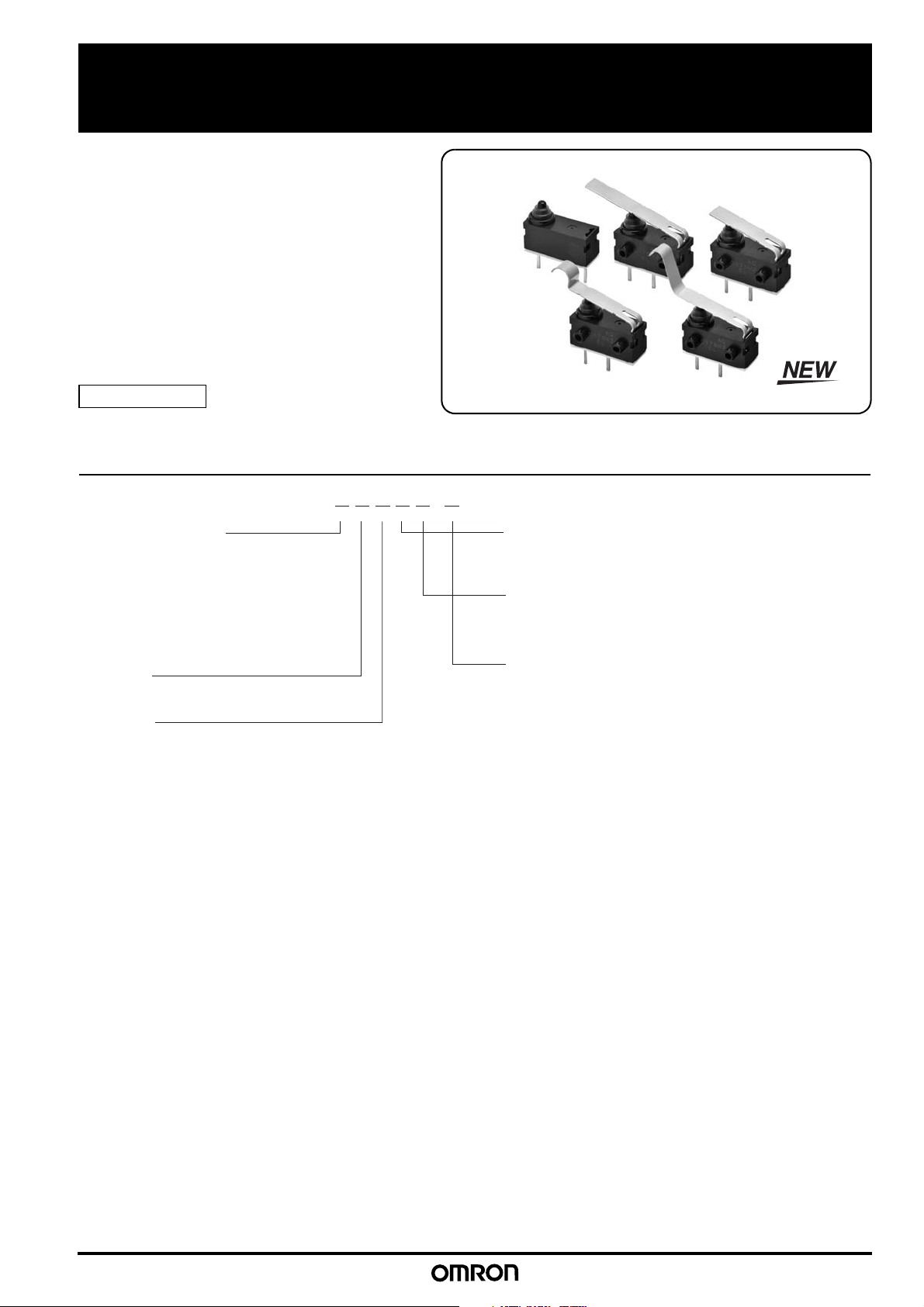
Sealed Ultra Subminiature Basic Switch
Long stroke seal switch with high reliability and high insulation performance
● <Clipping contact> Double reliability by twin contacts (=Clipping contact). Foreign materials are cleaned out by the sliding contacts.
● <Quiet operation> Quiet operating sound by sliding contact construction is needed for high grade car.
● <High insulation performance> High performance of Insulation resistance by unique contact structure.
RoHS Compliant
Model Number Legend
1
Page 2

D2AW Sealed Ultra Subminiature Basic Switch
Due to the idiosyncrasies of the automotive parts industry, a business decision is required on individual items to determine when to start supply. Contact your OMRON representative for information on individual models.
List of Models
Actuator
Pin plunger
Long straight leaf
lever
Leaf lever
Simulated roller
leaf lever
Long leaf lever
Model Without posts Long post on
Terminals Contact Form
Solder
terminals
PCB terminals
Solder
terminals
PCB terminals
Solder
terminals
PCB terminals
Solder
terminals
PCB terminals
Solder
terminals
PCB terminals
SPST-NC D2AW-A002H
SPST-NO D2AW-A003H
SPST-NC D2AW-A002D
SPST-NO D2AW-A003D
SPST-NC D2AW-A052H
SPST-NO D2AW-A053H
SPST-NC D2AW-A052D
SPST-NO D2AW-A053D
SPST-NC D2AW-A062H
SPST-NO D2AW-A063H
SPST-NC D2AW-A062D
SPST-NO D2AW-A063D
SPST-NC D2AW-A072H
SPST-NO D2AW-A073H
SPST-NC D2AW-A072D
SPST-NO D2AW-A073D
SPST-NC D2AW-A082H
SPST-NO D2AW-A083H
SPST-NC D2AW-A082D
SPST-NO D2AW-A083D
right
D2AW-BR002H D2AW-BL002H D2AW-C002H
D2AW-BR003H D2AW-BL003H D2AW-C003H
D2AW-BR002D D2AW-BL002D D2AW-C002D
D2AW-BR003D D2AW-BL003D D2AW-C003D
D2AW-BR052H D2AW-BL052H D2AW-C052H
D2AW-BR053H D2AW-BL053H D2AW-C053H
D2AW-BR052D D2AW-BL052D D2AW-C052D
D2AW-BR053D D2AW-BL053D D2AW-C053D
D2AW-BR062H D2AW-BL062H D2AW-C062H
D2AW-BR063H D2AW-BL063H D2AW-C063H
D2AW-BR062D D2AW-BL062D D2AW-C062D
D2AW-BR063D D2AW-BL063D D2AW-C063D
D2AW-BR072H D2AW-BL072H D2AW-C072H
D2AW-BR073H D2AW-BL073H D2AW-C073H
D2AW-BR072D D2AW-BL072D D2AW-C072D
D2AW-BR073D D2AW-BL073D D2AW-C073D
D2AW-BR082H D2AW-BL082H D2AW-C082H
D2AW-BR083H D2AW-BL083H D2AW-C083H
D2AW-BR082D D2AW-BL082D D2AW-C082D
D2AW-BR083D D2AW-BL083D D2AW-C083D
Long post on
left
M3-screw
mounting model
Short post on
right
D2AW-ER002H D2AW-EL002H
D2AW-ER003H D2AW-EL003H
D2AW-ER002D D2AW-EL002D
D2AW-ER003D D2AW-EL003D
D2AW-ER052H D2AW-EL052H
D2AW-ER053H D2AW-EL053H
D2AW-ER052D D2AW-EL052D
D2AW-ER053D D2AW-EL053D
D2AW-ER062H D2AW-EL062H
D2AW-ER063H D2AW-EL063H
D2AW-ER062D D2AW-EL062D
D2AW-ER063D D2AW-EL063D
D2AW-ER072H D2AW-EL072H
D2AW-ER073H D2AW-EL073H
D2AW-ER072D D2AW-EL072D
D2AW-ER073D D2AW-EL073D
D2AW-ER082H D2AW-EL082H
D2AW-ER083H D2AW-EL083H
D2AW-ER082D D2AW-EL082D
D2AW-ER083D D2AW-EL083D
Short post on
left
Contact Specifications
Contact
Minimum applicable load ( see note ) 5 VDC 1 mA
Note: For more information on the minimum applicable load, refer to Using Micro Loads.
Specification Slide
Material Sliver Plated
Ratings
Rating voltage Resistive load
12 VDC 0.1 A
Note: The rating values apply under the following test conditions.
1. Ambient temperature: 20 ± 2°C
2. Ambient humidity: 65 ± 5%
3. Operating frequency: 20 operations/min
2
Page 3

D2AW Sealed Ultra Subminiature Basic Switch
4
1.7 dia.
FP
OP
TTP
13.3
7
5.3
13.3
3
6.5
FP
OP
TTP
1.7 dia.
5.3
2.6
±0.05
1.5
–0.2
0
8
±0.1
8
±0.1
2.6
2.4
+0.1
0
2.4
+0.1
dia. holes
0
(depth:
D2AW-E@: 1.5 mm min.
D2AW-B@: 5 mm min.)
8±0.1
1.7 dia.
FP
OP
TTP
13.3
6.5
3
5.3
2.6±0.05
5
0
-0.2
FP
OP
TTP
18.5
6
2.65
13±0.1
1.5
0
-0.1
1.5
0
-0.1
5.3
6.5
3.1
+0.13
-0.03
3 dia.
3.3 dia. ±0.15
0
-0.1
Characteristics
Permissible operating speed 30 mm to 500 mm/s (pin plunger models)
Permissible operating
frequency
Insulation resistance 100 MΩ min. (at 500 VDC)
Contact resistance (initial value) 100 mΩ max.
Dielectric strength *1
Vibration resistance Malfunction 10 to 55 Hz, 1.5 mm double amplitude
Shock resistance
Durability *2
Degree of protection IEC IP67
Ambient operating temperature -40 to 85°C (at 60%RH max.) (with no icing or condesenation)
Ambient operation humidity 95%RH max. (for +5 to +35°C)
Weight Approx. 0.7 g (for pin plunger models with terminals)
Note: The data given above are initial values.
*1. The values for dielectric strength shown are for models with a Separator.
Refer to your OMRON website.
*2. For testing conditions, consult your OMRON sales representative.
Mechanical 30 operations/min max.
Electrical 20 operations/min max
Between terminals of the same polarity 600 VAC 50/60 Hz 1min
Between current-carrying metal parts and ground 1,500 VAC 50/60 Hz 1min
Between terminals and non-current-carrying
metal parts
1,500 VAC 50/60 Hz 1min
Destruction 1,000 m/s2 max.
Malfunction 300 m/s2 max.
Mechanical 200,000 operations min. (30 operations/min)
Electrical 200,000 operations min. (20 operations/min)
Mounting Structure and Reference Positions for Operating Characteristics (Unit: mm)
● Without posts
D2AW-A@
● Long post
D2AW-B@
● Short post
D2AW-E@
● M3-screw Mounting Models
D2AW-C@
Mounting Hole Dimensions (Reference)
3
Page 4

D2AW Sealed Ultra Subminiature Basic Switch
5.08
2-0.6
2.5
0.4
SPST-NCSPST-NO
4.38
2-1.22-2
1.8
0.4
Terminals (Unit: mm)
● PCB terminals
SPST-NO SPST-NC
● Solder terminals
SPST-NO SPST-NC
1.8
10.16
8.76
<PCB Mounting Dimensions
(Reference)>
+0.1
2-1
dia. holes
0
±0.1
2.5
2-0.6
3.5
2-1.22-2
0.4
0.4
5.08
2-1
+0.1
0
10.16
dia. holes
±0.1
4
Page 5

D2AW Sealed Ultra Subminiature Basic Switch
● Pin plunger
D2AW-@00@@
Operating
characteristics
Type
Without
posts
Models with
Posts
Operating Force OF Max.
Releasing Force RF Min.
1.00N {101 gf}
0.10N {10 gf}
Overtravel OT
Movement Differential MD Max.
1.4 mm (reference value)
0.25 mm
Free Position FP Max.
Operating Position OP
Total Travel Position TTP
11.2 mm
10.4 ± 0.3 mm
9.1 mm
7.2 mm
6.4 ± 0.3 mm
5.1 mm
20
2.65
3.4
6.5
3
8
±0.1
(1.7)
FP
OP
TTP
A
(0.35)
●Long straight leaf lever
D2AW-@05@@
Operating characteristics Type
Without
posts
Models with
Posts
Operating Force OF Max.
Releasing Force RF Min.
1.50N {152 gf}
0.10N {10 gf}
Overtravel OT
Movement Differential MD Max.
2.5 mm (reference value)
0.7 mm
Free Position FP Max.
Operating Position OP
Total Travel Position TTP
15.9 mm
12.1 ± 0.8 mm
10.0 mm
11.9 mm
8.1 ± 0.8 mm
6.0 mm
2.65A
14
(1.7)
8
±0.1
6.5
3
FP
OP
TTP
3.4
(0.35)
●Leaf lever
D2AW-@06@@
Operating
characteristics
Type
Without
posts
Models with
Posts
Operating Force OF Max.
Releasing Force RF Min.
2.00N {203 gf}
0.20N {20 gf}
Overtravel OT
Movement Differential MD Max.
1.8 mm (reference value)
0.5 mm
Free Position FP Max.
Operating Position OP
Total Travel Position TTP
13.3 mm
11.4 ± 0.5 mm
9.8 mm
9.3 mm
7.4 ± 0.5 mm
5.8 mm
16
R2
(1.7)
3.4
6.5
3
FP
OP
TTP
2.65
8
±0.1
(0.35)
A
●Simulated roller leaf lever
D2AW-@07@@
Operating
characteristics
Type
Without
posts
Models with
Posts
Operating Force OF Max.
Releasing Force RF Min.
1.80N {183gf}
0.20N {20 gf}
Overtravel OT
Movement Differential MD Max.
2.0 mm (reference value)
0.5 mm
Free Position FP Max.
Operating Position OP
Total Travel Position TTP
17.0 mm
14.8 ± 0.5 mm
12.9 mm
13.0 mm
10.8 ± 0.5 mm
8.9 mm
●Long leaf lever
D2AW-@08@@
Operating
characteristics
Type
Without
posts
Models with
Posts
Operating Force OF Max.
Releasing Force RF Min.
0.90N {91 gf}
0.05N {5 gf}
Overtravel OT
Movement Differential MD Max.
2.8 mm (reference value)
0.7 mm
Free Position FP Max.
Operating Position OP
Total Travel Position TTP
23.0 mm
19.4 ± 1.5 mm
16.8 mm
19.0 mm
15.4 ± 1.5 mm
12.8 mm
Dimensions (Unit: mm) / Operating Characteristics
The following illustrations and drawings are for solder terminal models. PCB terminal models are omitted from the drawings. Refer to Terminals for these terminals.
When ordering, replace @ with the code for the rating that you need. For the combination of models, refer to List of Models.
1.7 dia.
FP
OP
TTP
4
A
7
Note1. Unless otherwise specified, a tolerance of ±0.2 mm applies to all dimensions.
Note2. The operating characteristics are for operation in the A direction ( ).
A
FP
OP
TTP
6.5
(18)
2.65
3
±1
8
(0.45)
(1.7)
3.4
5
Page 6

D2AW Sealed Ultra Subminiature Basic Switch
Precautions
Please refer to "Safety Precautions for All Detection Switches" for correct use.
Cautions Correct Use
●Degree of Protection
• Do not use this product underwater.
Although molded lead wire models satisfy the test conditions
for the standard given below, this test is to check the ingress of
water into the switch enclosure after submerging the Switch in
water for a given time. Satisfying this test condition does not
mean that the Switch can be used underwater.
JIS C0920:
Degrees of protection provided by enclosures of electrical
apparatus (IP Code)
IEC 60529:
Degrees of protection provided by enclosures (IP Code)
Degree of protection: IP67
(check water intrusion after immersion
for 30 min. submerged 1m underwater)
• Do not operate the Switch when it is exposed to water spray,
or when water drops adhere to the Switch surface, or during
sudden temperature changes, otherwise water may intrude
into the interior of the Switch due to a suction effect.
• Prevent the Switch from coming into contact with oil and
chemicals.
Otherwise, damage to or deterioration of Switch materials may
result.
• Do not use the Switch in areas where it is exposed to silicon
adhesives, oil, or grease. Otherwise faulty contact may result
due to the generation of silicon oxide.
●Mounting
• Turn OFF the power supply before mounting or removing the
Switch, wiring, or performing maintenance or inspection.
Failure to do so may result in electric shock or burning.
• For models with posts, secure the posts by thermal caulking or
by pressing into an attached device. When pressed into an
attached device, provide guides on the opposite ends of the
posts to ensure that they do not fall out or rattle.
Thermal caulking conditions varies according to the equipment,
jig and base used for switch mounting. Consult your OMRON
sales representative for details.
●Operating Body
• Use an operating body with low frictional resistance and of a
shape that will not interfere with the sealing rubber, otherwise
the plunger may be damaged or the sealing may deteriorate.
●Handling
• Do not handle the Switch in a way that may cause damage to
the sealing rubber.
• When handling the Switch, ensure that pressure is not applied
to the posts in the directions shown in the following diagram.
Also, ensure that uneven pressure or pressure in a direction
other than the operating direction is not applied to the Actuator
as shown in the following diagram. Otherwise, the post,
Actuator, or Switch may be damaged, or the service life may
be reduced.
●Soldering
When soldering the lead wire to the terminal, first insert the
lead wire conductor through the terminal hole and then
conduct soldering.
Make sure that the temperature of the soldering iron tip does
not exceed 300°C, and complete the soldering within 3
seconds. Do not apply any external force for 1 minute after
soldering.
Soldering at an excessively high temperature or soldering for
more than 3 seconds may deteriorate the characteristics of the
Switch.
In case of automatic soldering, please do not apply the heat
beyond 260°C within 5 seconds. Pay careful attention so that
flux or solder liquid does not flow over the edge of the PCB
panel.
●Side-actuated (Cam/Dog) Operation
• When using a cam or dog to operate the Switch, factors such
as the operating speed, operating frequency, push-button
indentation, and material and shape of the cam or dog will
affect the durability of the Switch. Confirm performance
specifications under actual operating conditions before using
the Switch in applications.
●Using Micro Loads
• Even when using micro load models within the operating
range shown below, if inrush/surge current occurs, it may
increase the contact wear and so decrease durability.
Therefore, insert a contact protection circuit where necessary.
6
Page 7

MEMO
7
Page 8

• Application examples provided in this document are for reference only. In actual applications, confirm equipment functions and safety before using the product.
• Consult your OMRON representative before using the product under conditions which are not described in the manual or applying the product to nuclear control systems, railroad
systems, aviation systems, vehicles, combustion systems, medical equipment, amusement machines, safety equipment, and other systems or equipment that may have a serious
influence on lives and property if used improperly. Make sure that the ratings and performance characteristics of the product provide a margin of safety for the system or
equipment, and be sure to provide the system or equipment with double safety mechanisms.
OMRON Corporation
Electronic and Mechanical Components Company
Contact: www.omron.com/ecb
Cat. No. B130-E1-02
0517(1115)
Note: Do not use this document to operate the Unit.
 Loading...