

Page 1

New Product
SYSMAC CP-series CP1E CPU Units
CP1E-E@@D@-@
CP1E-N@@D@-@/NA20D@-@
The CP1E Package PLCs: Economical, Easy to use, and Efficient
■ The E-type Basic CPU Units provide cost
performance and easy application with only basic
functionality.
■ The N and NA-types Application CPU Units support
Programmable Terminal connection, position control,
and inverter connection
CP1E-E20DR-A
CP1E-N40DR-A
Features
• Programming, setting, and monitoring with CX-Programmer.
• Easy connection with computers using commercially available USB cables
• With E30/40, N30/40/60 or NA20 CPU Units, Add I/O by Connecting Expansion I/O Units.
• With E30/40, N30/40/60 or NA20 CPU Units, Add Analog I/O or Temperature Inputs by Connecting Expansion Units.
• Quick-response inputs
• Input interrupts
• Complete High-speed Counter Functionality.
• Versatile pulse control for Transistor Output for N14/20/30/40/60 or NA20 CPU Units.
• PWM Outputs for Transistor Output for N14/20/30/40/60 or NA20 CPU Units.
• Built-in RS-232C Port for N/NA-type CPU Units.
• Mounting Serial Option Boards to N30/40/60 or NA20 CPU Units.
• Built-in analog I/O, two inputs and one output, for NA-type CPU Units.
1
Page 2
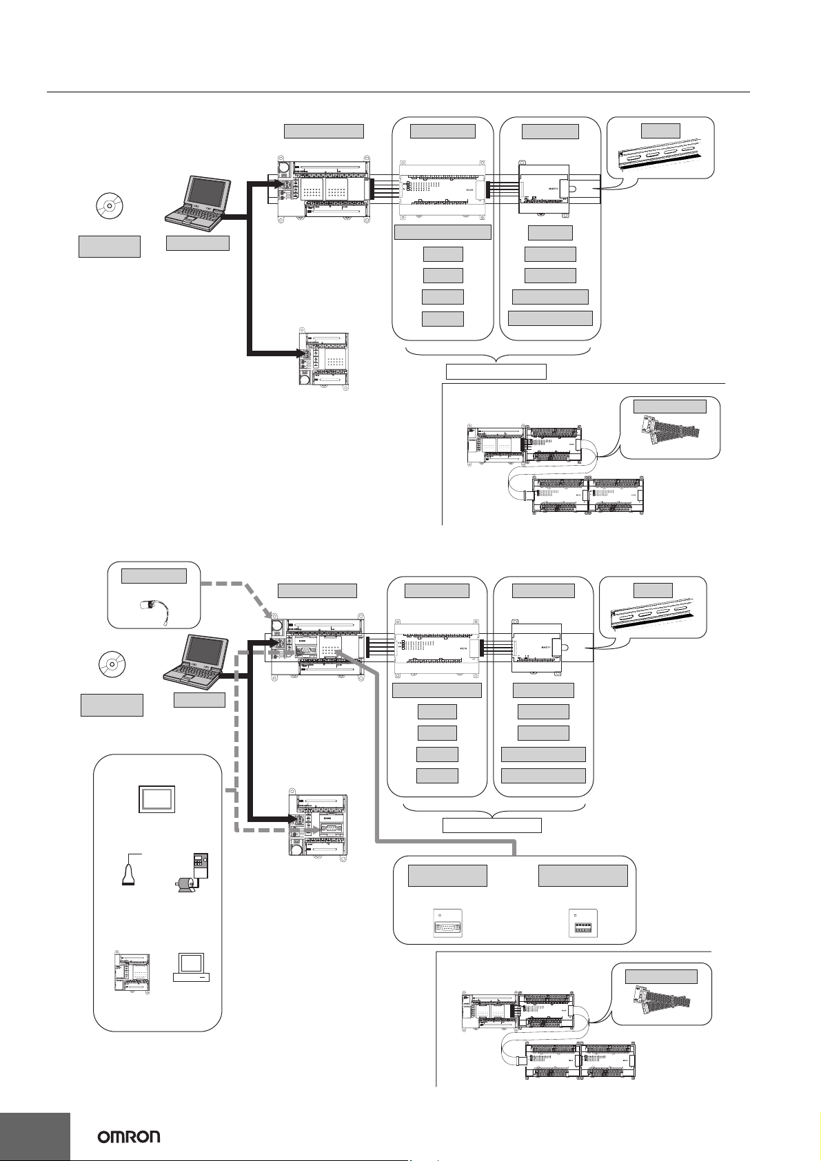
CP1E-E@@D@-@ CP1E-N@@D@-@/NA20D@-@
System Configuration
Basic System Configuration Using an E-type CPU Unit
Support Software
CX-Programmer
Personal computer
IBM PC/AT or equivalent
CP1E CPU Unit Expansion I/O Units Expansion Units
CP1E-E30DR-A
CP1E-E40DR-A
CP1E-E10D@-@
CP1E-E14DR-A
CP1E-E20DR-A
20 or 40 I/O Points
8 inputs
8 outputs
16 outputs
32 outputs
Up to 3 Units can be connected
When a two level layout is created by expansion and distance is required
CP1E CPU Unit
Analog I/O
Analog inputs
Analog outputs
Temperature sensors
CompoBus/S I/O Link Unit
Expansion Units and
Expansion I/O Units
DIN Track
I/O Connecting Cable
CP1W-CN811
Basic System Configuration Using an N/NA-type CPU Unit
Battery
Support Software
CX-Programmer
(NT Link/HOST Link)
General component
(No-protocol mode)
CP-series PLC or
CJ1M PLC
(Serial PLC Link)
CP1W-BAT01
Built in RS-232C
Programmable
Terminal (PT)
(Modbus-RTU)
Personal computer
IBM PC/AT or
equivalent
Inverter
Host computer
(Host Link)
CP1E CPU Unit
CP1E-N30D-
CP1E-N40D-
CP1E-N60D-
CP1E-NA20D-
CP1E-N14D-
CP1E-N20D-
Expansion I/O Units Expansion Units
20 or 40 I/O Points
8 inputs
8 outputs
16 outputs
32 outputs
Up to 3 Units can be connected
RS-232C Option Board
CP1W-CIF01
COMM
When a two level layout is created by expansion and distance is required
CP1E CPU Unit
Temperature sensors
CompoBus/S I/O Link Unit
Or
DIN Track
Analog I/O
Analog inputs
Analog outputs
*Neither the CP1W-DAM01 LCD Option Board nor the CP1W-CIF41
Ethernet Option Board can be used.
RS-422A/485 Option Board
CP1W-CIF11
CP1W-CIF12
COMM
Expansion Units and
Expansion I/O Units
I/O Connecting Cable
CP1W-CN811
2
Page 3
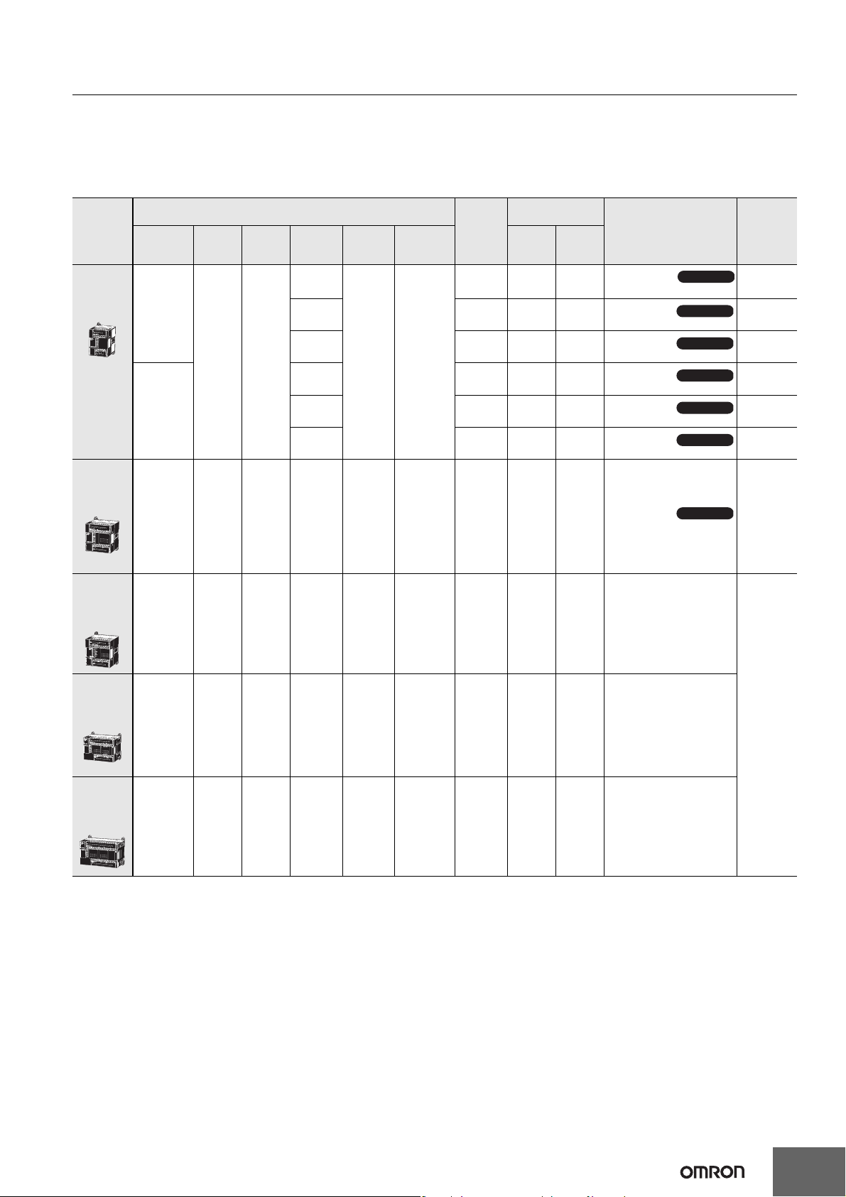
CP1E-E@@D@-@ CP1E-N@@D@-@/NA20D@-@
Ordering Information
International Standards
• The standards are abbreviated as follows: U: UL, U1: UL (Class I Division 2 Products for Hazardous Locations), C: CSA, UC: cULus,
UC1: cULus (Class I Division 2 Products for Hazardous Locations), CU: cUL, N: NK, L: Lloyd, and CE: EC Directives.
• Contact your OMRON representative for further details and applicable conditions for these standards.
E-type CP1E CPU Units (Basic Models)
Current
consumption (A)
Model Standards
5 V 24 V
Available soon
CP1E-E10DR-A
Available soon
CP1E-E10DT-A
Available soon
CP1E-E10DT1-A
Available soon
CP1E-E10DR-D
Available soon
CP1E-E10DT-D
Available soon
CP1E-E10DT1-D
Available soon
CP1E-E14DR-A
Product
name
E-type
CPU Units
with 10 I/O
Points
E-type
CPU Units
with 14 I/O
Points
Power
Supply
100 to 240
VAC
24 VDC
100 to 240
VAC
Specifications
Inputs Outputs
64
8 6 Relay 2K steps 2K words -- 0.16 0.07
Output
Relay
Transistor
(sinking)
Transistor
(sourcing)
Relay -- 0.08 0.04
Transistor
(sinking)
Transistor
(sourcing)
type
Program
capacity
2K
steps
Data
memory
capacity
2K
words
External
power
supply
(24 VDC)
(A)
-- 0.08 0.04
-- 0.11 --
-- 0.11 --
-- 0.11 --
-- 0.11 --
--
--
--
--
--
--
--
E-type
CPU Units
with 20 I/O
Points
E-type
CPU Units
with 30 I/O
Points
E-type
CPU Units
with 40 I/O
Points
100 to 240
VAC
100 to 240
VAC
100 to 240
VAC
12 8 Relay 2K steps 2K words -- 0.17 0.08 CP1E-E20DR-A
18 12 Relay 2K steps 2K words 0.30 0.17 0.07 CP1E-E30DR-A
24 16 Relay 2K steps 2K words 0.30 0.17 0.09 CP1E-E40DR-A
Note: There are no accessories included with E-type CP1E CPU Units. A Battery (CP1W-BAT01) cannot be used.
N, L, CE
3
Page 4
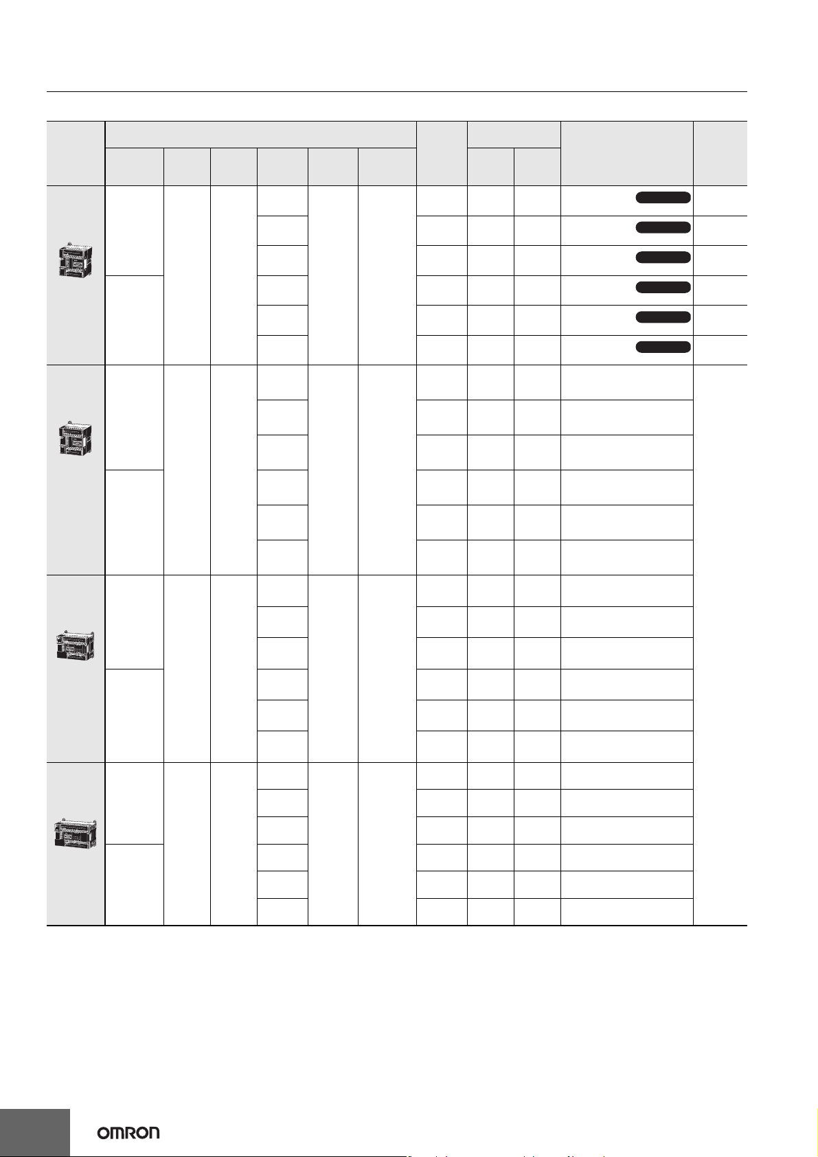
CP1E-E@@D@-@ CP1E-N@@D@-@/NA20D@-@
N/NA-type CP1E CPU Units (Application Models)
External
power
supply
(24 VDC)
(A)
-- 0.17 0.07
-- 0.22 0.02
-- 0.22 0.02
-- 0.22 0.02
-- 0.22 0.02
-- 0.18 0.08 CP1E-N20DR-A
-- 0.23 0.02 CP1E-N20DT-A
Product
name
N-type
CPU Units
with 14 I/O
Points
N-type
CPU Units
with 20 I/O
Points
Power
Supply
100 to 240
VAC
24 VDC
100 to 240
VAC
Specifications
Inputs Outputs
86
Output
Relay
Transistor
(sinking)
Transistor
(sourcing)
Relay -- 0.17 0.07
Transistor
(sinking)
Transistor
(sourcing)
Relay
Transistor
(sinking)
type
Program
capacity
8K
steps
Data
memory
capacity
8K
words
Current
consumption (A)
5 V 24 V
Model
CP1E-N14DR-A
CP1E-N14DT-A
CP1E-N14DT1-A
CP1E-N14DR-D
CP1E-N14DT-D
CP1E-N14DT1-D
Available soon
Available soon
Available soon
Available soon
Available soon
Available soon
Standards
--
--
--
--
--
--
N-type
CPU Units
with 30 I/O
Points
N-type
CPU Units
with 40 I/O
Points
24 VDC
100 to 240
VAC
24 VDC
100 to 240
VAC
24 VDC
12 8
18 12
24 16
Transistor
(sourcing)
Relay -- 0.18 0.08 CP1E-N20DR-D
Transistor
(sinking)
Transistor
(sourcing)
Relay
Transistor
(sinking)
Transistor
(sourcing)
Relay -- 0.21 0.07 CP1E-N30DR-D
Transistor
(sinking)
Transistor
(sourcing)
Relay
Transistor
(sinking)
Transistor
(sourcing)
Relay -- 0.21 0.09 CP1E-N40DR-D
Transistor
(sinking)
Transistor
(sourcing)
8K steps 8K words
8K steps 8K words
8K steps 8K words
-- 0.23 0.02 CP1E-N20DT1-A
-- 0.23 0.02 CP1E-N20DT-D
-- 0.23 0.02 CP1E-N20DT1-D
0.30 0.21 0.07 CP1E-N30DR-A
0.30 0.27 0.02 CP1E-N30DT-A
0.30 0.27 0.02 CP1E-N30DT1-A
-- 0.27 0.02 CP1E-N30DT-D
-- 0.27 0.02 CP1E-N30DT1-D
0.30 0.21 0.09 CP1E-N40DR-A
0.30 0.31 0.02 CP1E-N40DT-A
0.30 0.31 0.02 CP1E-N40DT1-A
-- 0.31 0.02 CP1E-N40DT-D
-- 0.31 0.02 CP1E-N40DT1-D
N, L, CE
4
Page 5
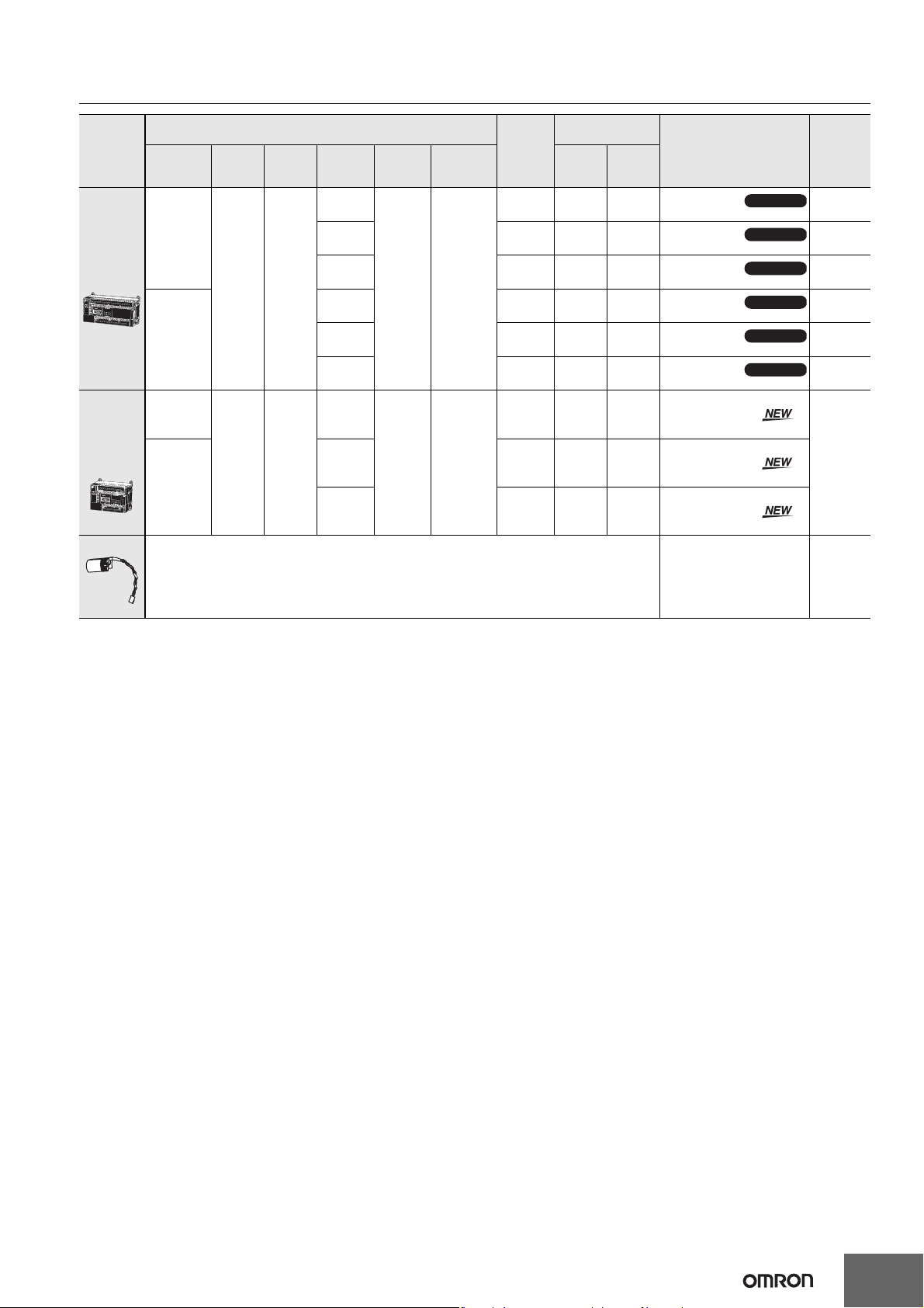
CP1E-E@@D@-@ CP1E-N@@D@-@/NA20D@-@
Product
name
N-type
CPU Units
with 60 I/O
Points
NA-type
CPU Units
with 20 I/O
Points
(Built-in
analog)
Battery Set For N/NA-type CP1E CPU Units
Power
Supply
100 to 240
VAC
24 VDC
100 to 240
VAC
24 VDC
Inputs Outputs
36 24
12
(Built-in
analog
inputs: 2)
Specifications
8
(Built-in
analog
outputs: 1)
External
power
Output
Relay
Transistor
(sinking)
Transistor
(sourcing)
Relay -- 0.21 0.13
Transistor
(sinking)
Transistor
(sourcing)
Relay
Transistor
(sinking)
Transistor
(sourcing)
type
Program
capacity
8K
steps
8K
steps
Data
memory
capacity
8K
words
8K
words
supply
(24 VDC)
(A)
0.30 0.21 0.13
0.30 0.31 0.02
0.30 0.31 0.02
-- 0.31 0.02
-- 0.31 0.02
0.30 0.18 0.11 CP1E-NA20DR-A
-- 0.23 0.09 CP1E-NA20DT-D
-- 0.23 0.09 CP1E-NA20DT1-D
Current
consumption (A)
5 V 24 V
Model
CP1E-N60DR-A
CP1E-N60DT-A
CP1E-N60DT1-A
CP1E-N60DR-D
CP1E-N60DT-D
CP1E-N60DT1-D
Available soon
Available soon
Available soon
Available soon
Available soon
Available soon
Standards
--
--
--
--
--
--
CE
Note: Mount a Battery to an N/NA-type CPU Unit if the data in the following areas must be
backed up for power interruptions.
• DM Area (D) (except backed up words in the DM Area), Holding Area (H), Counter Completion Flags (C),
Counter Present Values (C), Auxiliary Area (A), and Clock Function
(Use batteries within two years of manufacture.)
CP1W-BAT01 CE
Note: There are no accessories included with N/NA-type CP1E CPU Units. RS-232C connectors for the built-in RS-232C port and the Battery
(CP1W-BAT01) are not included.
5
Page 6

CP1E-E@@D@-@ CP1E-N@@D@-@/NA20D@-@
Options (for CP1E N30/40/60 or NA20 CPU Units)
The Options cannot be used for CP1E N14/20 CPU Units and all E-type CPU Units.
Product name Specifications Model Standards
RS-232C Option Board
RS-422A/485 Option Board
RS-422A/485 Isolated-type
Option Board
Note: It is not possible to use a CP-series Ethernet Option Board (CP1W-CIF41), LCD Option Board (CP1W-DAM01), or Memory Card (CP1W-
ME05M) with a CP1E CPU Unit.
Programming Devices
Product name
FA Integrated Tool Package
CX-One Lite
Ver.4.@
CX-One FA Integrated Tool
Package Ver. 4.@
Note: The E20, E30, E40, N20, N30 and N40 CPU Units are supported by CX-Programmer version 8.2 or higher.
The E10, E14, N14, N60, and NA20 CPU Units are supported by CX-Programmer version 9.03 or higher.
When Micro PLC Edition CX-Programmer is used, you need version 9.03 or higher.
* Site licenses are available for the CX-One (3, 10, 30 or 50 licenses).
One RS-232C Option Board can be
mounted to the Option Board slot.
For CP1E N30/40/60 or NA20 CPU
Units only.
One RS-232C connector is included.
One RS-422A/485 Option Board can be
mounted to the Option Board slot.
For CP1E N30/40/60 or NA20 CPU
Units only.
Specifications
CX-One Lite is a subset of the complete CX-One package that
provides only the Support Software required for micro PLC
applications.
CX-One Lite runs on the following OS.
Windows 2000 (Service Pack 4 or higher), XP, Vista, or 7
(except 64-bit edition)
CX-One Lite Ver. 4.@ includes Micro PLC Edition CXProgrammer Ver.9.@.
CX-One is a package that integrates the Support Software for
OMRON PLCs and components. CX-One runs on the
following OS.
OS: Windows 2000 (Service Pack 4 or higher), XP, Vista, or 7
(except 64-bit edition)
CX-One Ver. 4.@ includes CX-Programmer Ver. 9.@.
CP1W-CIF01
CP1W-CIF11
CP1W-CIF12 N, L, CE
Number of
licenses
1 license CD
CD
1 license *
DVD
Media
UC1, N, L, CE
Model Standards
CXONE-LT01C-V4
CXONE-AL01C-V4
CXONE-AL01D-V4
--
--
The following tables lists the Support Software that can be installed from CX-One
Support Software in CX-One
Micro PLC Edition CX-Programmer Ver.9.@ Yes No CX-Drive Ver.1.@ Yes Yes
CX-Programmer Ver.9.@ No Yes CX-Process Tool Ver.5.@ No Yes
CX-Integrator Ver.2.@ Yes Yes Faceplate Auto-Builder for NS Ver.3.@ No Yes
Switch Box Utility Ver.1.@ Yes Yes CX-Designer Ver.3.@ Yes Yes
CX-Protocol Ver.1.@ No Yes NV-Designer Ver.1.@ Yes Yes
CX-Simulator Ver.1.@ Yes Yes CX-Thermo Ver.4.@ Yes Yes
CX-Position Ver.2.@ No Yes CX-ConfiguratorFDT Ver.1.@ Yes Yes
CX-Motion-NCF Ver.1.@ No Yes CX-FLnet Ver.1.@ No Yes
CX-Motion-MCH Ver.2.@ No Yes Network Configurator Ver.3.@ Yes Yes
CX-Motion Ver.2.@ No Yes CX-Server Ver.4.@ Yes Yes
CX-One Lite
Ver.4.@
CX-One
Ver.4.@
Support Software in CX-One
CX-One Lite
Ver.4.@
CX-One
Ver.4.@
Note: For details, refer to the CX-One Catalog (Cat. No. R134).
6
Page 7

CP1E-E@@D@-@ CP1E-N@@D@-@/NA20D@-@
Expansion I/O Units and Expansion Units (for CP1E E30/40, N30/40/60, or NA20 CPU Units)
CP1E E10/14/20 or N14/20 CPU Units do not support Expansion I/O Units and Expansion Units.
Current
consumption (A)
5 V 24 V
Model Standards
Unit type Product name
Input Unit
Specifications
Inputs Outputs
8----0.018--CP1W-8ED
Output
type
CP1W
Expansion I/O
Units
CP1W
Expansion
Units
Output Units
I/O Units
Analog Input Unit
Analog Output Unit
Analog I/O Unit
Temperature
Sensor Unit
CompoBus/S
I/O Link Unit
Relay 0.026 0.044 CP1W-8ER
-- 8
-- 16
-- 32
12 8
24 16
4 analog inputs
Input range: 0 to 5 V, 1 to 5 V, 0 to 10 V,
0 to 20 mA, or 4 to 20 mA.
Resolution: 1/6000
4 analog outputs
Output range: 0 to 5 V, 1 to 5 V, 0 to 10 V,
0 to 20 mA, or 4 to 20 mA.
Resolution: 1/6000
2 analog inputs and 1 analog output
I/O range: 0 to 5 V, 1 to 5 V, 0 to 10 V,
0 to 20 mA, or 4 to 20 mA.
Resolution: 1/6000
2 temperature sensor inputs
Sensor type: Thermocouple (J or K)
4 temperature sensor inputs
Sensor type: Thermocouple (J or K)
2 temperature sensor inputs
Sensor type: Platinum resistance thermometer
4 temperature sensor inputs
Sensor type: Platinum resistance thermometer
CompoBus/S slave
8 inputs and 8 outputs
(Pt100 or JPt100)
(Pt100 or JPt100)
Transistor
(sinking)
Transistor
(sourcing)
Relay 0.042 0.090 CP1W-16ER
Transistor
(sinking)
Transistor
(sourcing)
Relay 0.049 0.131 CP1W-32ER
Transistor
(sinking)
Transistor
(sourcing)
Relay 0.103 0.044 CP1W-20EDR1
Transistor
(sinking)
Transistor
(sourcing)
Relay 0.080 0.090 CP1W-40EDR
Transistor
(sinking)
Transistor
(sourcing)
±10 V,
±10 V,
±10 V,
0.075 -- CP1W-8ET
0.075 -- CP1W-8ET1
0.076 -- CP1W-16ET
0.076 -- CP1W-16ET1
0.113 -- CP1W-32ET
0.113 -- CP1W-32ET1
0.130 -- CP1W-20EDT
0.130 -- CP1W-20EDT1
0.160 -- CP1W-40EDT
0.160 -- CP1W-40EDT1
0.100 0.090 CP1W-AD041
0.080 0.124 CP1W-DA041
0.083 0.110 CP1W-MAD11
0.040 0.059 CP1W-TS001
0.040 0.059 CP1W-TS002
0.054 0.073 CP1W-TS101
0.054 0.073 CP1W-TS102
0.029 -- CP1W-SRT21
U, C, N, L, CE
N, L, CE
N, L, CE
U, C, N, L, CE
N, L, CE
UC1, N, L, CE
U, C, N, L, CE
I/O Connecting Cable
Product name Specifications Model Standards
I/O Connecting Cable
Note: An I/O Connecting Cable (approx. 6 cm) for horizontal connection is provided with CP1W Expansion I/O Units and Expansion Units.
80 cm (for CP1W Expansion I/O Units and Expansion Units)
Only one I/O Connecting Cable can be used in each PLC.
CP1W-CN811 UC1, N, L, CE
7
Page 8

CP1E-E@@D@-@ CP1E-N@@D@-@/NA20D@-@
General Specifications
Type AC power supply models DC power supply models
Model CP1E-@@@D@-A CP1E-@@@D@-D
Enclosure Mounted in a panel
CPU Unit with 10 I/O points (CP1E-E10D@-@): 90mm *1 ×85mm *2 × 66 mm
CPU Unit with 14 or 20 I/O points (CP1E-@14D@-@/@20D@-@): 90mm *1 × 85mm *2 × 86 mm
Dimensions (H × D × W)
Weight
Supply voltage 100 to 240 VAC 50/60 Hz 24 VDC
Operating voltage
range
Power consumption
Electrical
specifications
Application
environment
Terminal block Fixed (not removable)
Terminal screw size M3
Applicable standards Conforms to EC Directive
Grounding method Ground to 100 Ω or less.
Inrush current
External power supply
*3
Insulation resistance
Dielectric strength
Power OFF detection
time
Ambient operating
temperature
Ambient humidity 10% to 90%
Atmosphere No corrosive gas.
Ambient storage
temperature
Altitude 2,000 m max.
Pollution degree 2 or less: Conforms to JIS B3502 and IEC 61131-2.
Noise resistance 2 kV on power supply line (Conforms to IEC61000-4-4.)
Overvoltage category Category II: Conforms to JIS B3502 and IEC 61131-2.
EMC Immunity Level Zone B
Vibration resistance
Shock resistance
* 1 Total of 110 mm with mounting brackets.
* 2 Excluding cables.
* 3 Use the external power supply to power input devices. Do not use it to drive output devices.
* 4 This is the rated value for the maximum system configuration. Use the following formula to calculate power consumption for CPU Units with
DC power.
Formula: DC power consumption = (5V current consumption ✕ 5 V/70% (internal power efficiency) + 24V current consumption) ✕ 1.1(current
fluctuation factor)
The above calculation results show that a DC power supply with a greater capacity is required.
CPU Unit with 30 I/O points (CP1E-@30D@-@): 90mm *1 × 85mm *2 × 130 mm
CPU Unit with 40 I/O points (CP1E-@40D@-@): 90mm *1 × 85mm *2 × 150 mm
CPU Unit with 60 I/O points (CP1E-N60D@-@): 90mm *1 ×85mm *2 × 195 mm
CPU Unit with 20 I/O points and built-in analog (CP1E-NA20D@-@): 90mm *1 ×85mm *2 × 130 mm
CPU Unit with 10 I/O points (CP1E-E10D@-@): 300g max.
CPU Unit with 14 I/O points (CP1E-@14D@-@): 360g max.
CPU Unit with 20 I/O points (CP1E-@20D@-@): 370g max.
CPU Unit with 30 I/O points (CP1E-@30D@-@): 600g max.
CPU Unit with 40 I/O points (CP1E-@40D@-@): 660g max.
CPU Unit with 60 I/O points (CP1E-N60D@-@): 850g max.
CPU Unit with 20 I/O points and built-in analog (CP1E-NA20D@-@): 680g max.
85 to 264 VAC 20.4 to 26.4 VDC
15 VA/100 VAC max.
25 VA/240 VAC max.
(CP1E-E10D@-A/@14D@-A/@20D@-A)
50 VA/100 VAC max.
70 VA/240 VAC max.
(CP1E-NA20D@-A/@30D@-A/@40D@-A/N60D@-A)
120 VAC, 20 A for 8 ms max. for cold start at room
temperature
240 VAC, 40 A for 8 ms max. for cold start at room
temperature
Not provided.
(CP1E-E10D@-A/@14D@-A/@20D@-A)
24 VDC, 300 mA
(CP1E-NA20D@-A/@30D@-A/@40D@-A/N60D@-A)
20 MΩ min. (at 500 VDC) between the external AC
terminals and GR terminals
2,300 VAC 50/60Hz for 1 min between AC external
and GR terminals Leakage current: 5 mA max.
10 ms min. 2 ms min.
0 to 55 °C
-20 to 75 °C (excluding battery)
Conforms to JIS 60068-2-6.
5 to 8.4 Hz with 3.5-mm amplitude, 8.4 to 150 Hz
Acceleration of 9.8 m/s
Conforms to JIS 60068-2-27.
2
, 3 times in X, Y, and Z directions
147 m/s
2
for 100 min in X, Y, and Z directions (10 sweeps of 10 min each = 100 min total)
9 W max. (CP1E-E10D@-D)
13 W max. (CP1E-N14D@-D/N20D@-D)
20 W max.
(CP1E-NA20D@-D/N30D@-D/N40D@-D/N60D@-D) *4
24 VDC, 30 A for 20 ms max. for cold start at room
temperature
Not provided
Except between DC primary current and DC
secondary current
Except between DC primary current and DC
secondary current
8
Page 9

Performance Specifications
CP1E-E@@D@-@ CP1E-N@@D@-@/NA20D@-@
Item CP1E-@@D@-@
Program capacity
Control method Stored program method
I/O control method Cyclic scan with immediate refreshing
Program language Ladder diagram
Instructions Approximately 200
Processing
speed
Number of CP1W-series Expansion Units
connected
Maximum number of I/O points
Built-in I/O
Built-in input
functions
Built-in output
functions
Built-in analog
Analog adjusters 2 adjusters (Setting range: 0 to 255)
Overhead processing time 0.4 ms
Instruction execution times
High-speed
counter mode/
maximum
frequency
High-speed
counters
Input interrupts
Quick-response Inputs
Normal input
Pulse outputs
(Models with
transistor
outputs only)
Pulse outputs
(Models with
transistor
outputs only)
Counting
mode
Count value 32 bits
Counter reset
modes
Control
method
Input
constants
Pulse output
method and
output
frequency
Output mode
Number of
output pulses
Acceleration/
deceleration
curves
Changing SVs
during
instruction
execution
Origin
searches
Frequency
Duty factor
Output mode Continuous Mode
Analog input
Analog output Setting range: 0 to 6,000 (1 channels only for NA-type)
2 K steps (8 Kbytes) including the symbol table,
comments, and program indices of the CX-Programmer
Basic instructions (LD): 1.19 µs min.
Special instructions (MOV): 7.9 µs min.
CP1E-E10D@-@/@14D@-@/@20D@-@: None
CP1E-@30D@-@/@40D@-@/N60D@-@/NA20D@-@: 3 units
CP1E-E10D@-@ : 10
CP1E-@14D@-@ : 14
CP1E-@20D@-@ : 20
CP1E-@30D@-@ : 150 (30 built in, 40 × 3 expansion)
CP1E-@40D@-@ : 160 (40 built in, 40 × 3 expansion)
CP1E-N60D@-@ : 180 (60 built in, 40 × 3 expansion)
CP1E-NA20D@-@: 140 (20 built in, 40 × 3 expansion)
CP1E-E10D@-@ : 10 (6 inputs, 4 outputs)
CP1E-@14D@-@ : 14 (8 inputs, 6 outputs)
CP1E-@20D@-@ : 20 (12 inputs, 8 outputs)
CP1E-@30D@-@ : 30 (18 inputs, 12 outputs)
CP1E-@40D@-@ : 40 (24 inputs, 16 outputs)
CP1E-N60D@-@ : 60 (36 inputs, 24 outputs)
CP1E-NA20D@-@: 20 (12 inputs, 8 outputs)
Incremental Pulse Inputs
10 kHz: 6 counters
5 counters (only for 10 I/O points)
Up/Down Inputs
10 kHz: 2 counters
Pulse + Direction Inputs
10 kHz: 2 counters
Differential Phase Inputs (4x)
5 kHz: 2 counters
Linear mode
Ring mode
Phase Z and software reset (excluding increment pulse input)
Software reset
Target Matching
Range Comparison
6 inputs (4 inputs only for 10 I/O points)
Interrupt input pulse width: 50 µs min.
6 inputs (4 inputs only for 10 I/O points)
Input pulse width: 50 µs min.
Delays can be set in the PLC Setup (0 to 32 ms, default: 8 ms).
Set values: 0, 1, 2, 4, 8, 16, or 32 ms
Pulse output function not included
PWM output function not included
Analog function not included
CP1E-N@@D@-@
CP1E-NA@@D@-@
8 K steps (32 Kbytes) including the symbol table,
comments, and program indices of the CX-Programmer
Incremental Pulse Inputs
100 kHz: 2 counters,10 kHz: 4 counters
Up/Down Inputs
100 kHz: 1 counters,10 kHz: 1 counters
Pulse + Direction Inputs
100 kHz: 2 counters
Differential Phase Inputs (4x)
50 kHz: 1 counter, 5 kHz: 1 counter
Pulse + Direction Mode
1 Hz to 100 kHz: 2 outputs
Continuous mode (for speed control)
Independent mode (for position control)
Relative coordinates: 0000 0000 to 7FFF FFFF hex
(0 to 2147483647)
Absolute coordinates: 8000 0000 to 7FFF FFFF hex
(-2147483647 to 2147483647)
Trapezoidal acceleration and deceleration
(Cannot perform S-curve acceleration and
deceleration.)
Only target position can be changed.
Included
2.0 to 6,553.5 Hz (in increments of 0.1 Hz) with 1 output
or 2 Hz to 32,000 Hz (in increments of 1 Hz) with 1 output
0.0% to 100.0% (in increments of 0.1%)
Accuracy: +1%/-0% at 2 Hz to 10,000 Hz and
Setting range: 0 to 6,000 (2 channels only for NA-type)
+5%/-0% at 10,000 Hz to 32,000 kHz
9
Page 10
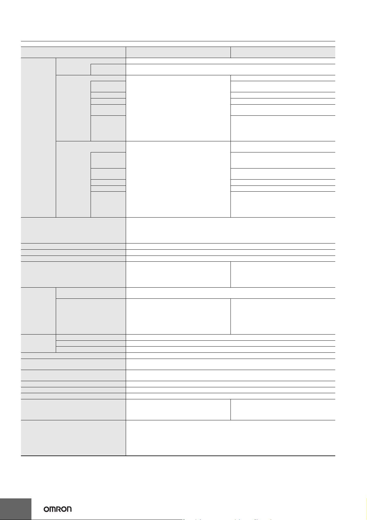
CP1E-E@@D@-@ CP1E-N@@D@-@/NA20D@-@
Item CP1E-E@@D@-@
B-type Peripheral USB Port Conforming to USB 2.0 B type connector
Built-in RS-232C port
Communications
Serial Option port
Number of tasks
Maximum subroutine number 128
Maximum jump number 128
Scheduled interrupt tasks 1 interrupt task
Clock
Built-in EEPROM
Memory
backup
CIO Area
Work Area (W) 1,600 bits (100 words): W0.00 to W99.15 (W0 to W99)
Holding Area (H)
Auxiliary Area (A)
Temporary Relay Area (TR) (TR Area) 16 bits: TR0 to TR15
Timer Area (T) 256 timer numbers (T0 to T255 (separate from counters))
Counter Area (C) 256 counter numbers (C0 to C255 (separate from timers))
Data Memory Area (D)
Operating modes
Battery backup With
CP1W-BAT01 Battery
(Sold separately)
Input Bits 1,600 bits (100 words): CIO 0.00 to CIO 99.15 (CIO 00 to CIO 99)
Output Bits 1,600 bits (100 words): CIO 100.00 to CIO 199.15 (CIO 100 to CIO 199)
Serial PLC Link Words 1,440 bits (90 words): CIO 200.00 to CIO 289.15 (words CIO 200 to CIO 289)
Transmission
distance
Communications
method
synchronization
Baud rate 1.2, 2.4, 4.8, 9.6, 19.2, 38.4, 57.6, or 115.2 kbps
Transmission
distance
Supported
protocol
Mountable
Option Boards
Communications
method
synchronization
Baud rate 1.2, 2.4, 4.8, 9.6, 19.2, 38.4, 57.6, or 115.2 kbps
Compatible
protocols
5 m max.
Interface: Conforms to EIA RS-232C.
Half duplex
Start-stop
No built-in RS-232C port
Option Board cannot be mounted.
17
• One cyclic execution task
• One scheduled interrupt task (always interrupt task 1)
• Six input interrupt tasks (interrupt tasks 2 to 7)
• Sixteen high-speed counter interrupt tasks (interrupt tasks 1 to 16)
Clock function not included.
The time of error occurrence displays 01-01-01
01:01:01 Sunday
Ladder programs and parameters are automatically saved to built-in EEPROM
A section of the Data Memory Area can be saved to the built-in EEPROM.
Battery cannot be mounted.
800 bits (50 words): H0.00 to H49.15 (H0 to H49)
Bits in this area maintain their ON/OFF status when operating mode is changed.
Read-only: 7,168 bits (448 words) A0 to A447
Read/write: 4,896 bits (306 words) in words A448 to A753
2 Kwords: D0 to D2047
Of these, 1,500 words can be saved to the backup
memory (built-in EEPROM) using settings in the
Auxiliary Area.
PROGRAM mode: Program execution is stopped.
MONITOR mode: Programs are executed.
RUN mode: Programs are executed.
Preparations can be executed prior to program execution in this mode.
Some operations, such as online editing, and changes to present values in I/O memory, are
enabled in this mode.
This is the normal operating mode.
15 m max.
1 port (Option Board can be mounted only to N30/40/
60 and NA20 CPU Units.)
Depends on Option Board.
Depends on Option Board.
Included.
Accuracy (monthly deviation):
-4.5 min to -0.5 min at ambient temperature of 55
-2.0 min to +2.0 min at ambient temperature of 25
-2.5 min to +1.5 min at ambient temperature of 0
CP1W-BAT01 can be used.
Maximum battery service life: 5 years
Backup Time
Guaranteed value (ambient temperature: 55
13,000 hours (approx. 1.5 years)
Effective value (ambient temperature: 25
43,000 hours (approx. 5 years)
8 Kwords: D0 to D8191
Of these, 7,000 words can be saved to the backup
memory (built-in EEP-ROM) using settings in the
Auxiliary Area
CP1E-N@@D@-@
CP1E-NA@@D@-@
• Host Link
• 1:N NT Link
• No-protocol mode
• Serial PLC Links (master, slave)
• Modbus-RTU Easy Master
• One RS-232C port: CP1W-CIF01
•
One RS-422A/485 port (not isolated): CP1W-CIF11
• One RS-422A/485 port (isolated): CP1W-CIF12
• Host Link
• 1:N NT Link
• No-protocol mode
• Serial PLC Links (master, slave)
• Modbus-RTU Easy Master
o
C):
o
C):
o
C,
o
C,
o
C
10
Page 11
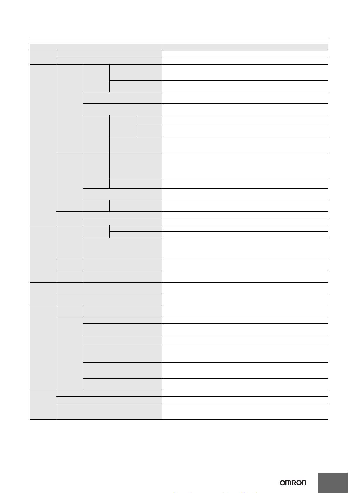
CP1E-E@@D@-@ CP1E-N@@D@-@/NA20D@-@
Function Specifications
Function Function description
Cycle time
management
CPU Unit
built-in
functions
Expansion
I/O Units
and
Expansion
Units
Memory
management
functions
Communic
ations
Interrupt
Minimum cycle time Makes the cycle time consistent.
Monitoring the cycle time Monitors the cycle time.
High-speed
counter
inputs
Interrupt inputs
Inputs
Outputs
Built-in
analog
Functions
supported
by both
Expansion
I/O Unit and
Expansion
Unit
Expansion
I/O Units
Expansion
Units
Holding I/O memory when changing operating modes
Automatic backup to the backup memory
(built-in EEPROM)
Peripheral
USB port
Serial port (N/NA-type only) --
Scheduled interrupts Tasks can be executed at a specified interval (1.0 ms min., Unit: 0.1 ms).
Interrupt inputs Interrupt tasks are processed when the built-in input turns ON or OFF.
High-speed counter interrupts
Quick-response inputs
Normal
inputs
Pulse
outputs
(Models
with
transistor
outputs
only)
PWM outputs
(Models with transistor outputs only)
Normal
outputs
Analog input Convert analog signal into digital value range from 0 to 6,000.
Analog output Convert digital value range from 0 to 6,000 into analog signal.
I/O
refreshing
Load OFF function
Input response times
Unit error detection
Peripheral bus (toolbus) For communications with programming device (CX-Programmer).
Host Link (SYSWAY) communications
No-protocol communications
NT Link communications
Serial PLC Links
Modbus-RTU Easy Master function
High-speed pulse inputs
Input pulse frequency
measurement
Cyclic
I/O
refreshing
Input response times
Pulse control
Origin positioning Origin searches and origin returns
Load OFF function
Cyclic refreshing The Expansion I/O Units and Expansion Units are cyclically refreshed.
Refreshing by IORF I/O refreshing by IORF instruction
refreshing
Immediate
refreshing
High-speed pulses from devices such as a rotary encoder are counted.
The counted values are stored in the Auxiliary Area.
Interrupt tasks can be executed when target is reached or by range comparison.
The frequency of pulses input by the PRV instruction is measured.
Relevant interrupt tasks are executed during the cycle when the CPU Unit built-in inputs
turn ON or turn OFF.
Inputs can be read without being affected by cycle time.
Use the quick-response inputs to read signals shorter than the cycle time.
The CPU Unit’s built-in I/O are cyclically refreshed.
I/O refreshing by immediate refreshing instructions
Input constants can be set for Basic I/O Units.
The response time can be increased to reduce the effects of chattering and noise at input
contacts. The response time can be decreased to enable detecting shorter input pulses.
A pulse signal is output and positioning or speed control is performed with a servo driver
that accepts a pulse input.
Continuous mode for speed control or independent mode for position control can be used.
There are functions for changing to positioning during speed control and for changing the
target value during positioning.
Pulses for which the duty ratio (ratio between ON time and OFF time during one pulse
cycle) can be set are output.
All of the outputs on the CPU Unit’s I/O can be turned OFF when an error occurs in RUN
or MONITOR mode.
All of the outputs on Expansion I/O Units and Expansion Units are turned OFF (0000 hex)
when an error occurs in RUN or MONITOR mode.
The response time can be increased to reduce the effects of chattering and noise at input
contacts. The response time can be decreased to enable detecting shorter input pulses.
Errors in Expansion Units are detected. The CPU Unit is notified that the Expansion Unit
stopped due to an error.
The status of I/O memory can be held when the operating mode is changed.
The forced-set/reset status can be held when the operating mode is changed.
Automatic backup of ladder programs and parameter area to the backup memory
(built-in EEPROM)
Host Link commands can be sent from a PT or a computer to read/write I/O memory, and
perform other operations for PLC.
I/O instructions for communications ports (TXD/RXD instructions) can be used for data
transfer with peripheral devices such as bar code readers.
I/O memory in the PLC can be allocated and directly linked to various PT functions,
including status control areas, status notification areas, touch switches, lamps, memory
tables, and other objects.
Up to ten words per Unit can be shared by up to nine CPU Units, including one Polling Unit
and eight Polled Units.
Note: Programmable Terminal (PT) cannot be connected.
Modbus-RTU commands are sent by the Modbus-RTU Master function. Modbus slaves,
such as inverters, can be easily controlled with serial communications.
This function counts input pulses with the CPU Unit’s built-in high-speed counter and
executes an interrupt task when the count reaches the preset value or falls within a preset
range (target value or zone comparison).
11
Page 12

CP1E-E@@D@-@ CP1E-N@@D@-@/NA20D@-@
Function
Power supply
management
Debugging
Self-diagnosis
and restoration
Maintenance Automatic online connection via network
Security
functions
Memory protection
Number of power interruptions counter The number of times power has been interrupted is counted.
Online editing The program can be changed during operation in MONITOR mode or PROGRAM mode.
Force-set/reset Specified bits can be set or reset.
Differentiate monitoring ON/OFF changes in specified bits can be monitored.
Storing the stop position at errors The location and task number where execution stopped for a program error is recorded.
Program check
Error Log Details and the time of occurrence of error codes predefined by the CPU Unit are stored.
CPU error detection CPU Unit WDT errors are detected.
User-defined failure diagnosis
Load OFF function
System FAL error detection
(User-defined non-fatal error)
Backup memory error detection
Non-fatal error
detection
Fatal Error
Detection
Read protection using password
Write protection from FINS commands This function prohibits writing by using FINS commands sent over the network.
PLC Setup error detection This function detects setting errors in the PLC Setup.
Option Board errors This function detects when the Option Board is malfunctioning or disconnected.
Battery error detection
(N/NA-type CPU Units only)
Built-in analog error
Memory error detection This function detects errors that occur in memory of the CPU Unit.
I/O bus error detection
Too Many I/O Points Error
Detection
Program error detection
Instruction processing error
detection
Indirect DM addressing BCD
error
Illegal area access error
detection
No END error detection This function detects an error when there is no END instruction at the end of the program.
Task error detection
overflow error detection
Invalid instruction error
detection
User program area overflow
error detection
Cycle time exceeded error
detection
System FALS error detection
(user-defined fatal error)
Function description
Holding Area data, DM Area data, Counter Completion Flags, and counter present values
are held even when power is turned OFF.
This function can be used only with an N/NA-type CPU Unit and only when the Battery Set
(sold separately) is mounted.
The programs can be checked for items such as no END instruction and FALS/FAL errors
at startup.
Errors can be generated for user-specified conditions:
Non-fatal errors (FAL) and fatal errors (FALS).
The built-in outputs, Expansion I/O Unit outputs, and Expansion Unit outputs are turned
OFF.
This function generates a non-fatal (FAL) error when the user-defined conditions are met
in program.
This function detects when data in the backup memory (built-in EEPROM) that stores the
ladder program is corrupted.
This function detects when the battery voltage is low or the battery is disconnected.
Note: This function is valid only when a battery is mounted and the Do not detect battery
error Check Box is cleared in the PLC Setup.
This function detects when a built-in analog I/O error occurs and stops the operation of builtin analog I/O.
This function detects errors that occur during data transfer between the CPU Unit and
another Unit.
This function detects when more than the maximum number of CP1W Expansion I/O Units
and Expansion Units are connected to the PLC.
This function detects when there is an error in the program.
See the following for details.
This function detects an error when the given data value is invalid when executing an
instruction, or execution of instruction between tasks was attempted.
This function detects an error when an indirect DM address in BCD mode is not BCD.
This function detects an error when an attempt is made to access an illegal area with an
instruction operand.
The execution condition for an interrupt task was met but there is no interrupt task with the
specified number.
This function detects an error when too many differentiated instructions are entered or
deleted during online editing (131,072 times or more).
This function detects an error when an attempt is made to execute an instruction that is not
defined in the system.
This function detects an error when instruction data is stored after the last address in user
program area.
This function monitors the cycle time (10 to 1,000 ms) and stops the operation when the set
value is exceeded.
This function generates a fatal (FALS) error when the user-defined conditions are met in
program.
This function enables automatically connecting to the PLC online when the CX-Programmer
is directly connected by a serial connection (peripheral USB port or serial port).
This function protects user memory.
Read protection: Set a password using the CX-Programmer.
Overwrite protection is not provided.
12
Page 13

CP1E-E@@D@-@ CP1E-N@@D@-@/NA20D@-@
Internal Memory in the CPU Units
CPU Unit Memory Backup Structure
The internal memory in the CPU Unit consists of built-in RAM and built-in EEPROM. The built-in RAM is used as execution memory and the builtin EEPROM is used as backup memory.
CPU Unit
Built-in EEPROM Built-in RAM
Backup memory
User Program Area
(Backup)
PLC Setup PLC Setup
Backup using bit in Auxiliary Area
DM Area DM Area
DM Area data read at startup
Data is retained even if the power
supply is interrupted for longer
than the backup time of the built-in
capacitor.
Automatic backup
Read at startup
Automatic backup
Read at startup
Execution Memory
User Program Area
I/O Memory Areas
If a CP1W-BAT01 Battery (sold
separately) is mounted to an N/NA-type
CPU Unit, which is normally backed up
by a built-in capacitor, data will be
backed up by the battery.
Area where data is backed up
even if the power supply is
interrupted for longer than the
back-up time of the built-in
capacitor.
Area where data is cleared if
the power supply is
interrupted for longer than the
back-up time of the built-in
capacitor.
●Precautions for Correct Use
Create a system and write the ladder programs so that problems will not occur in the system if the data in these area may be unstable.
• Data in areas such as the DM area (D), Holding Area (H), the Counter Present Values (C) and the status of Counter Completion Flags (C), which
is retained by the battery, may be unstable when the power supply is turned off (Except for the DM area that are retained by the built-in EEPROM using the Auxilliary Area bit.)
• The error log, and clock data (N/NA-type CPU Unit only) in the Auxiliary Area will become unstable. Other words and bits in the Auxiliary Area
will be cleared to their default values.
The built-in capacitor’s backup time varies with the ambient temperature as shown in the following graph.
Backup time of built-in capacitor
50 hours
40 hours
25 hours
20 hours
9 hours
7 hours
CP1E E-type CPU Unit
CP1E N/NA-type CPU Unit
25 40 60
Ambient temperature
13
Page 14

CP1E-E@@D@-@ CP1E-N@@D@-@/NA20D@-@
I/O Memory Areas
Data can be read and written to I/O memory from the ladder programs. I/O memory consists of an area for I/O with external devices, user areas,
and system areas.
System Areas
Input bits (starting from CIO 0)
Work Area (W)
Holding Area (H)
User Areas
DM Area (D)
Timer Area (T)
Counter Area (C)
Auxiliary Area
(A)
Condition Flags
Clock Pulses
Output bits (starting from CIO 100)
I/O Memory Areas
Name No. of bits Word addresses Remarks
Input Bits 1,600 bits (100 words) CIO 0 to CIO 99 For NA-type, CIO90, CIO91 is occupied by analog input 0, 1.
CIO Area
Work Area (W) 1,600 bits (100 words) W0 to W99 --
Holding Area (H) 800 bits (50 words) H0 to H49
Data Memory Area (D)
Timer Area (T)
Counter Area (C)
Auxiliary Area (A)
Output Bits 1,600 bits (100 words) CIO 100 to CIO 199 For NA-type, CIO190 is occupied by analog output 0.
Serial PLC Link Words 1,440 bits (90 words) CIO 200 to CIO 289 --
Data in this area is retained during power interruptions if a
Battery Set (sold separately) is mounted to an N/NA-type CPU
Unit.
Data in specified words of the DM Area can be retained in the
E-type CPU Unit 2K words D0 to D2047
N/NA-type CPU Unit 8K words D0 to D8191
Present values 256
Timer Completion Flags 256 --
Present values 256
Counter Completion Flags 256 --
Read only 7168 bits (448 words) A0 to A447 Data in this area is retained during power interruptions if a
Read-write 4,896 bits (306 words) A448 to A753
T0 to T255
C0 to C255
built-in EEPROM in the backup memory by using a bit in the
Auxiliary Area.
Applicable words: D0 to D1499
Data in specified words of the DM Area can be retained in the
built-in EEPROM in the backup memory by using a bit in the
Auxiliary Area.
Applicable words: D0 to D6999
Data in this area is retained during power interruptions if a
Battery Set (sold separately) is mounted to an N/NA-type CPU
Unit.
Battery Set (sold separately) is mounted to an N/NA-type CPU
Unit.
(One word can be specified at a time.)
(One word can be specified at a time.)
--
14
Page 15
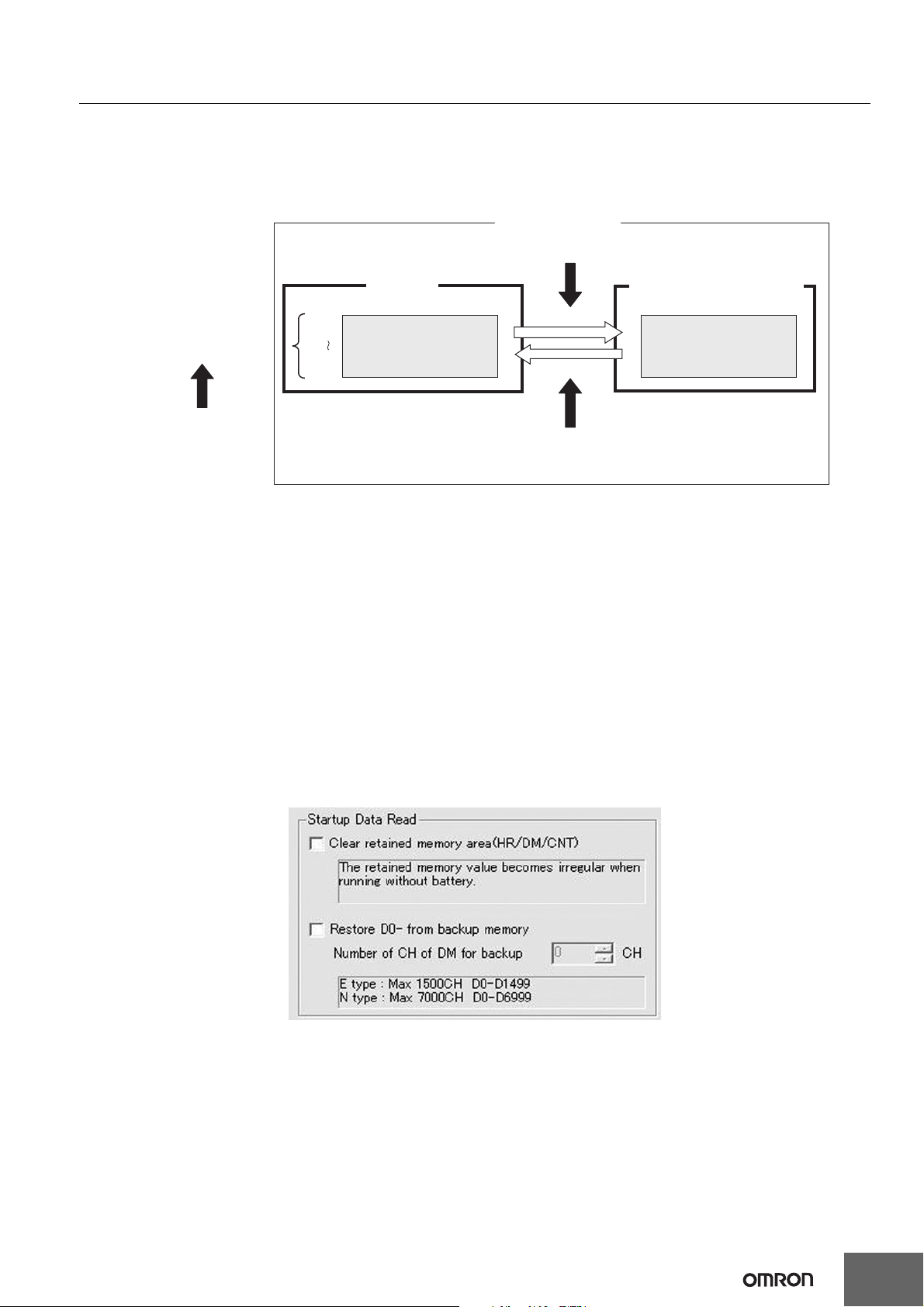
CP1E-E@@D@-@ CP1E-N@@D@-@/NA20D@-@
Backing Up and Restoring DM Area Data
The contents of the DM Area (D) will become unstable if the power supply is interrupted for longer than the backup time of the built-in capacitor
(50 hours for an E-type CPU Unit, 40 hours for an N/NA-type CPU Unit without a Battery).
The contents of the specified words in the DM Area data can be backed up from RAM to the built-in EEPROM backup memory during operation
by turning ON a bit in the Auxiliary Area. The number of DM Area words to back up is specified in the Number of CH of DM for backup Box in the
PLC Setup. If the Restore D0- from backup memory Check Box is selected in the PLC Setup, the backup data will automatically be restored to
RAM when the power is turned back ON so that data is not lost even if power is interrupted.
CP1E CPU Unit
A751.15 (DM Backup Save Start Bit) turned ON
Specified number of words
Specify the number of words starting
from D0 in the Number of CH of DM
for backup Box in the Startup Data
Read Area in PLC Setup.
D0
D(n-1)
Built-in RAM
DM Area (D)
Data backed up
Data restored
DM backup data is restored to the RAM when power supply is
turned ON again if the Restore D0- from backup memory Check
Box is selected in the Startup Data Read Area in the PLC Setup.
Built-in EEPROM Backup Memory
DM backup data
Conditions for Executing Backup
Specified words starting from D0 in the RAM can be saved to the built-in EEPROM backup memory by turning ON A751.15.
(These words are called the DM backup words and the data is called the DM backup data.)
A751.15 (DM Backup Save Start Bit) can be used in any operating mode (RUN, MONITOR, or PROGRAM mode).
Words That Can Be Backed Up
• E-type CP1E CPU Units: D0 to D1499
• N/NA-type CP1E CPU Units: D0 to D6999
Number of Words To Back Up
The number of words to back up starting from D0 is set in the Number of CH of DM for backup Box in the Startup Data Read Area in the PLC Setup.
Restoring DM Backup Data to RAM When Power Is Turned ON
The DM backup data can be restored to RAM when power is turned ON by selecting the Restore D0- from backup memory Check Box in the
Startup Data Read Area in the PLC Setup.
The DM backup data will be read from the backup memory even if the Clear retained memory area (HR/DM/CNT) Check Box is selected in the
PLC Setup.
15
Page 16
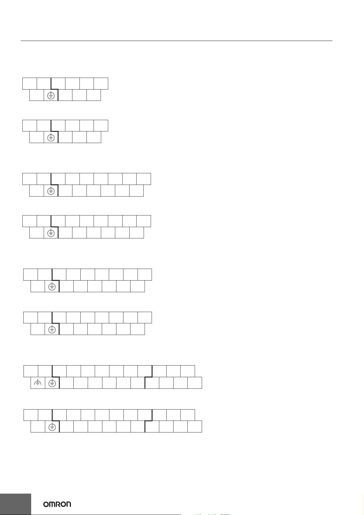
CP1E-E@@D@-@ CP1E-N@@D@-@/NA20D@-@
Built-in Inputs
Terminal Arrangements
●Input Terminal Arrangement for CPU Unit with 10 I/O Points
AC power supply models
CIO 0
L1 L2/N
DC power supply models
+
●Input Terminal Arrangement for CPU Unit with 14 I/O Points
AC power supply models
L1 L2/N
COM 01 03 05
00 02 04NC
CIO 0
−
COM 01 03 05
00 02 04NC
CIO 0
COM 01 03 05 07 NC NC
00 02 04 06 NC NCNC
DC power supply models
CIO 0
+
−
COM 01 03 05 07 NC NC
00 02 04 06 NC NCNC
●Input Terminal Arrangement for CPU Unit with 20 I/O Points
AC power supply models
CIO 0
L1 L2/N
DC power supply models
+−
COM 01 03 05 07 09 11
00 02 04 06 08 10NC
CIO 0
COM 01 03 05 07 09 11
00 02 04 06 08 10NC
●Input Terminal Arrangement for CPU Unit with 30 I/O Points
AC power supply models
CIO 0 CIO 1
L1 L2/N
COMNC01 03 05 07 09 11
01 03 05
DC power supply models
CIO 0 CIO 1
+−
NC
COM
16
00 02 04 06 08 10
01 03 05 07 09 11
00 02 04 06 08 10
00 02 04
01 03 05
00 02 04
NC
Page 17
CP1E-E@@D@-@ CP1E-N@@D@-@/NA20D@-@
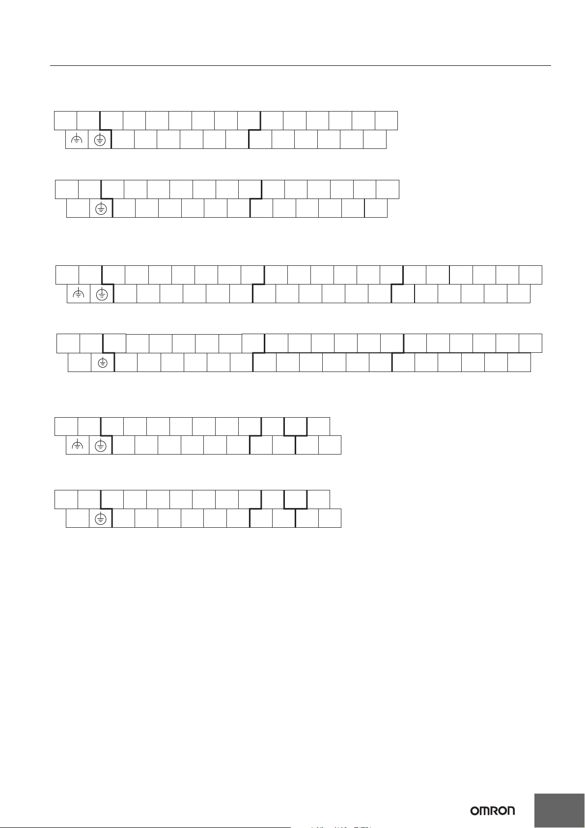
●Input Terminal Arrangement for CPU Unit with 40 I/O Points
AC power supply models
CIO 0 CIO 1
L1 L2/N
COM 01 03 05
07 09 11
01 03 05
07 09
11
00 02 04
DC power supply models
CIO 0 CIO 1
+−
COMNC01 03 05
00 02 04
06 08 10
07 09 11
06 08 10
00 02 04
01 03 05
00 02 04
06 08 10
07 09
06 08 10
11
●Input Terminal Arrangement for CPU Unit with 60 I/O Points
AC power supply models
CIO 0 CIO 1 CIO 2
L1 L2/N
DC power supply models
+
COM 01 03 05
00 02 04
CIO 0 CIO 1 CIO 2
COM
−
01 03 05 07 09 11
02
07 09 11
06 08 10
06 10
04 08
01 03 05
00 02 04
01 03 05 07 09 11
00 0000 02
04
07 09
06 08 10
06
08
11
00 02 04
10
01 03 05
01 03 05 07 09 11
02
●Input Terminal Arrangement for CPU Unit with 20 I/O Points and Built-in Analog
AC power supply models
CIO 0 CIO 90 CIO 91
L1 L2/N
01 03 05 07 09 11
COM
I IN0 AG I IN1
06 08 10
06
04
07 09
08
11
10NC
00 02 04 06 08 10
DC power supply models
CIO 0 CIO 90 CIO 91
+
-
COM
01 03 05 07 09 11
00NC 02 04 06 08 10
VIN0
COM0
I IN0 AG I IN1
VIN0
COM0
VIN1
VIN1
COM1
COM1
17
Page 18
CP1E-E@@D@-@ CP1E-N@@D@-@/NA20D@-@
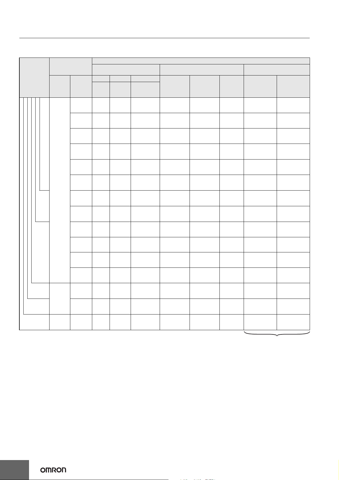
Allocating Built-in Inputs to Functions
Input terminals are allocated functions by setting parameters in the PLC Setup. Set the PLC Setup so that each terminal is used for only one function.
Settings in PLC Setup
High-speed counter 0 to 3 setting on
Built-in Input Tab Page
(increment
Two-phase
(differential
phase x4 or
up/down)
Counter 0, phase
A or up input
Two-phase
(pulse/
direction)
Counter 0,
pulse input
Origin search settings on Pulse
Output 0/1 Tab Page
CPU Unit with
20 to 60 points
-- --
CPU Unit with
14 I/O points
CPU Unit with
I/O Points
Input terminal block
Terminal
block
label
Terminal
number
00
Interrupt input setting on
Built-in Input Tab Page
Normal Interrupt Quick
Normal
input
Normal
input 0
Input
interrupt
-- --
Quick-
response
input
Single-phase
pulse input)
Counter 0,
increment input
01
02
10
03
04
05
CIO 0
06
14
07
08
09
20
10
11
30
CIO 1
40 06 to 11
60 CIO 2 00 to 11
00 to 05
Normal
input 1
Normal
input 2
Normal
input 3
Normal
input 4
Normal
input 5
Normal
input 6
Normal
input 7
Normal
input 8
Normal
input 9
Normal
input 10
Normal
input 11
Normal
input 12
to17
Normal
input 18
to 23
Normal
input 24
to 35
-- --
Interrupt
input 2
Interrupt
input 3
Interrupt
input 4
Interrupt
input 5
Interrupt
input 6
Interrupt
input 7
Quick-response
input 2
Quick-response
input 3
Quick-response
input 4
Quick-response
input 5
Quick-response
input 6
Quick-response
input 7
-- -- -- -- -- -- --
-- -- -- -- -- -- --
-- -- -- -- --
-- -- -- -- --
-- -- -- -- -- -- --
-- -- -- -- -- -- --
-- -- -- -- -- -- --
Counter 1,
increment input
Counter 2,
increment input
--
Counter 3,
increment input
Counter 4,
increment input
Counter 5,
increment input
-- -- --
Counter 0, phase
B or down input
Counter 1, phase
A or up input
Counter 1, phase
B or down input
Counter 0, phase
Z or reset input
Counter 1, phase
Z or reset input
-- --
Counter 1,
pulse input
Counter 0,
direction
Counter 1,
direction
Counter 0,
reset input
Counter 1,
reset input
-- --
-- --
--
-- --
--
Pulse 0: Origin
input signal
Pulse 1: Origin
input signal
Pulse 0: Origin
proximity input signal
Pulse 1: Origin
proximity input signal
Pulse 0, Origin
proximity input
signal
Pulse 1, Origin
proximity input
signal
Pulse 0, Origin
proximity input
signal
Pulse 1, Origin
proximity input
signal
--
--
18
These functions are supported only by
N/NA-type CPU Units with transistor
outputs.
Page 19
CP1E-E@@D@-@ CP1E-N@@D@-@/NA20D@-@
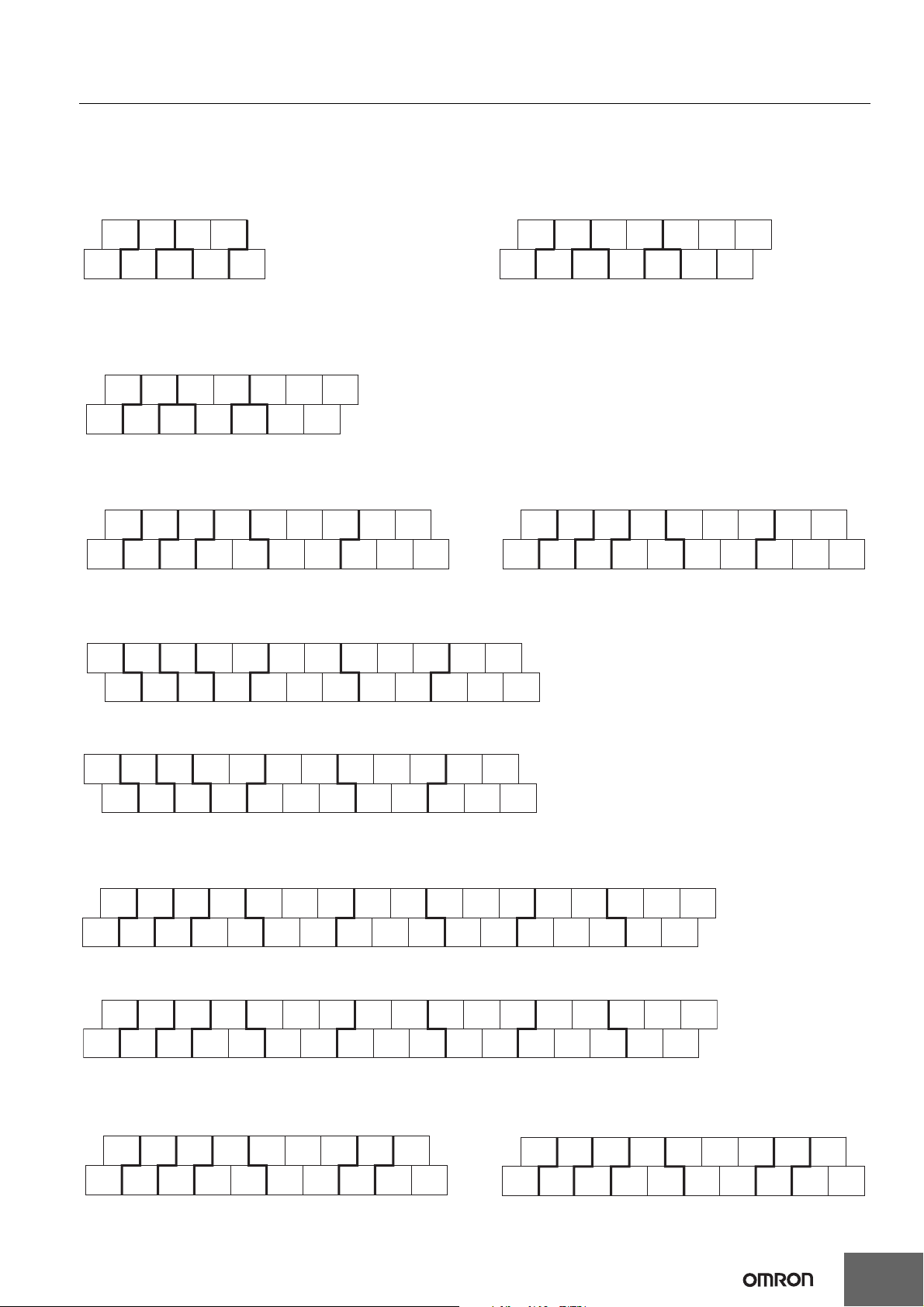
Built-in Outputs
Terminal Arrangements
●Output Terminal Arrangement for CPU Unit
with 10 I/O Points
AC power supply model
DC power supply model
●Output Terminal Arrangement for CPU Unit
with 14 I/O Points
AC power supply model
DC power supply model
00 01 02 03
COM COM NC COM NC
CIO 100
00 01 02 03
COM COM NC COM
CIO 100
●Output Terminal Arrangement for CPU Unit with 20 I/O Points
AC power supply model
DC power supply model
00 01 02 03
COM COM NC COM
CIO 100
04 05 07
06
COMNC
●Output Terminal Arrangement for CPU Unit with 30 I/O Points
AC power supply model DC power supply model
00 01 02 04 05 07 00
+
- COM COMCOM COM COM
CIO 100 CIO 101
03 06
02
01 03
00 01 02 04 05 07 00
NC
NC COM COMCOM COM COM
CIO 100 CIO 101
●Output Terminal Arrangement for CPU Unit with 40 I/O Points
AC power supply model
+0001
02 03 04 06 00 01
03 04 06
04 05 NC
NC
COMNC
03 06
02
01 03
COM COM 05 07 COM
CIO 100 CIO 101
DC power supply model
NC 00 010702 03 04 06 00 01
COM COM 05 07 COM
CIO 100 CIO 101
02 05COMCOMCOM-
03 04 06
02 05
COMCOMCOMNC
07
●Output Terminal Arrangement for CPU Unit with 60 I/O Points
AC power supply model
+ 0001020405070002040507
COMCOM- COM 03 COM 06 COM 01 03 COM 0600COM0201040305COM0706
CIO 100
DC power supply model
NC 00 01 02 04 05 07 00 02 04 05 07
COMCOMNC COM 03 COM 06 COM 01 03 COM 0600COM0201040305COM0706
CIO 100
CIO 101
CIO 101
CIO 102
CIO 102
●Output Terminal Arrangement for CPU Unit with 20 I/O Points and Built-in Analog
AC power supply model DC power supply model
00 01 02 04 05 07 NC
+
COM COMCOM COM NC
−
CIO 100 CIO 190
03 06
IOUT0
VOUT0
COM0
NC
00
NC
COM COM COM COM NC
CIO 100 CIO 190
020104 05 07 NC
03 06
IOUT0
VOUT0
COM0
19
Page 20
CP1E-E@@D@-@ CP1E-N@@D@-@/NA20D@-@
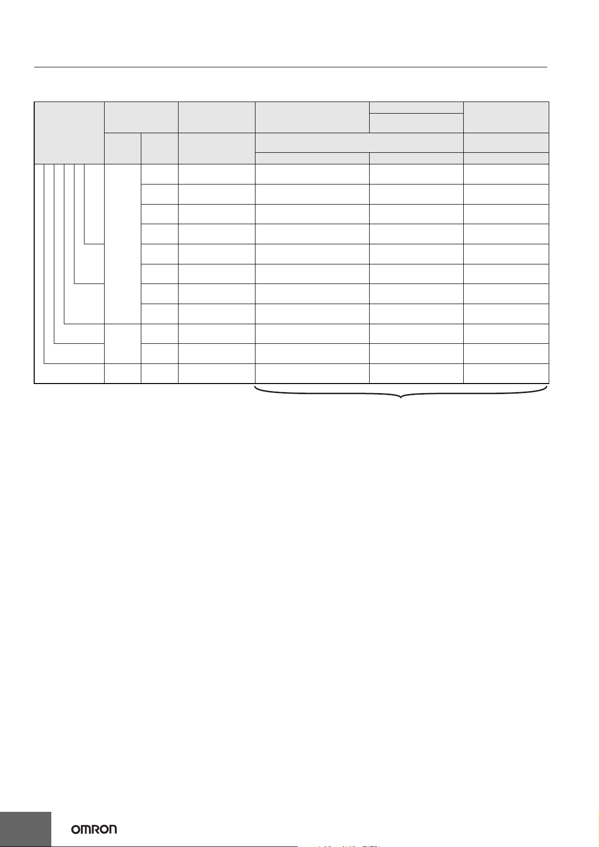
Allocating Built-in Output Terminals to Functions
Output terminals are allocated functions by setting parameters in the PLC Setup. Set the PLC Setup so that each terminal is used for only one function.
Setting in PLC Setup
Origin search setting on
Pulse Output 0/1 Tab Page
When the PWM
instruction is executed
Variable duty ratio
pulse output
CPU Unit with
I/O points
Output terminal
block
Terminal
block label
Terminal
Other than those
shown right
number
00 Normal output 0 Pulse output 0 (pulse) -- --
Normal output
When a pulse output instruction
(SPED, ACC, PLS2, or ORG) is
executed
Fixed duty ratio pulse output
Pulse + direction Use PWM output
10
CIO 100
14
20
30
CIO 101
40 04 to 07 Normal output 12 to 15 -- -- --
60 CIO 102 00 to 07 Normal output 16 to 23 -- -- --
01 Normal output 1 Pulse output 1 (pulse) -- PWM output 0
02 Normal output 2 Pulse output 0 (direction) -- --
03 Normal output 3 Pulse output 1 (direction) -- --
04 Normal output 4 --
05 Normal output 5 --
06 Normal output 6 -- -- --
07 Normal output 7 -- -- --
00 to 03 Normal output 8 to 11 -- -- --
These functions are supported only by N/NA-type CPU Units with transistor outputs.
Pulse 0: Error counter reset
output
Pulse 1: Error counter reset
output
--
--
20
Page 21
CP1E-E@@D@-@ CP1E-N@@D@-@/NA20D@-@
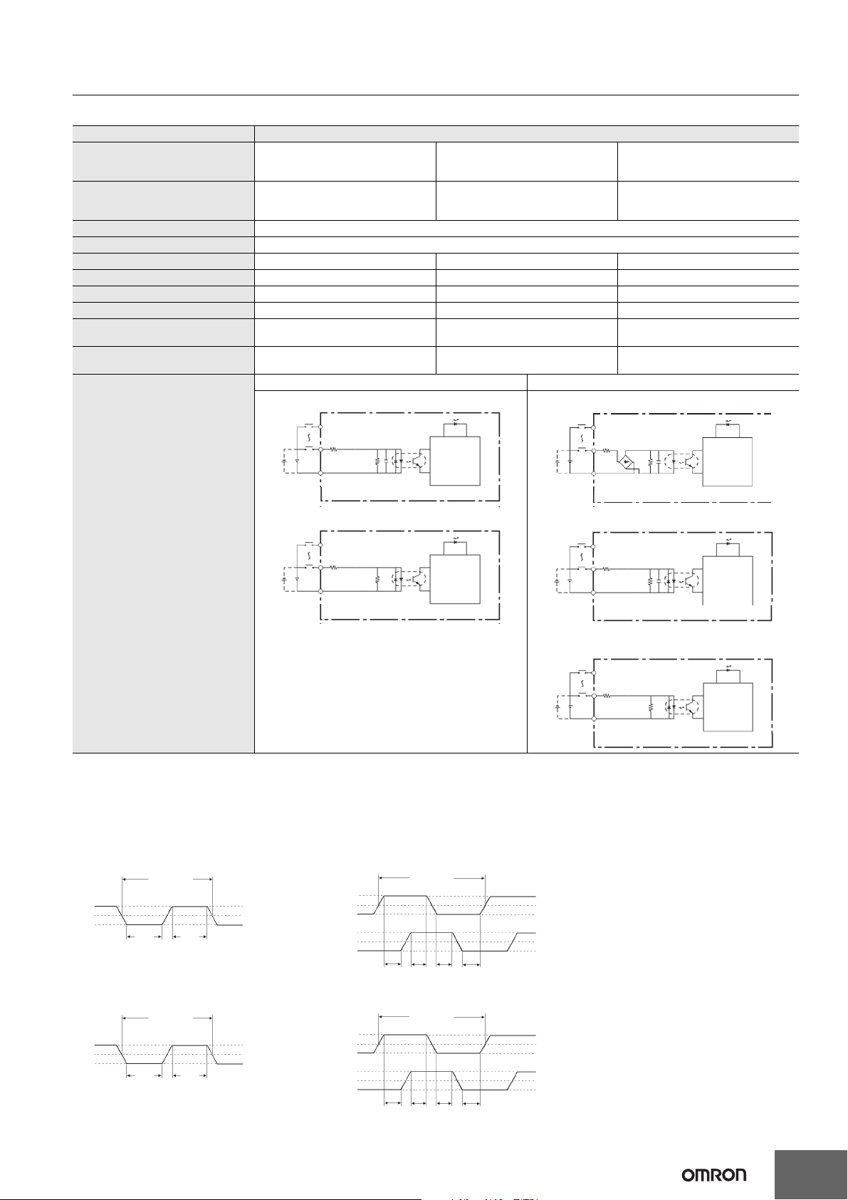
I/O Specifications for CPU Units
Input Specifications
Item Specification
Input type
High-speed counter inputs or Normal
Inputs
Input bits CIO 0.00 to CIO 0.01 CIO 0.02 to CIO 0.07 *1
Input voltage 24 VDC, +10%, -15%
Applicable sensors 2-wire and 3-wire sensors
Input Impedance 3.3 kΩ 3.3 kΩ 4.8 kΩ
Input current 7.5 mA typical 7.5 mA typical 5 mA typical
ON voltage/current 3 mA min. at 17.0 VDC min. 3 mA min. at 17.0 VDC min. 3 mA min. at 14.4 VDC min.
OFF voltage/current 1 mA max. at 5.0 VDC max. 1 mA max. at 5.0 VDC max. 1 mA max. at 5.0 VDC max.
ON response time *2
OFF response time *2
E-type CPU Unit: 50 µs min.
N/NA-type CPU Unit: 2.5 µs min.
E-type CPU Unit: 50 µs min.
N/NA-type CPU Unit: 2.5 µs min.
E-type CPU Unit N/NA-type CPU Unit
Input 0.00 to 0.07
COM
IN
3.3kΩ
IN
Input indicator
1000pF
910Ω
High-speed counter inputs, interrupt
input, quick-response inputs, or Normal
Inputs
Normal inputs
CIO 0.08 to CIO 0.11,
CIO 1.00 to CIO 1.11 and
CIO 2.00 to CIO 2.11 *1
50 µs max. 1 ms max.
50 µs max. 1 ms max.
Input 0.00 to 0.01
Internal
circuits
COM
IN
3.3kΩ
IN
Input indicator
1000pF
4.3kΩ
Internal
circuits
Circuit configuration
Input 0.08 to 0.11, 1.00 to 1.11
COM
IN
4.8kΩ
IN
Input indicator
750Ω
Internal
circuits
Input 0.02 to 0.07
IN
3.3kΩ
IN
COM
Inputs CIO 0.08 to CIO 0.11, CIO 1.00 to CIO 1.11 and
CIO 2.00 to CIO 2.11
IN
4.8kΩ
IN
COM
Input indicator
1000pF
910Ω
Input indicator
750Ω
Internal
circuits
Internal
circuits
* 1 The bits that can be used depend on the model of CPU Unit.
* 2 The response time is the delay caused by hardware. The delay set in the PLC Setup (0 to 32 ms, default: 8 ms) for a normal input must be
added to this value.
Pulse plus direction input mode,
Increment mode
Up/down input mode
Differential phase mode
N/NA-type: 0.00/0.01 N/NA-type: 0.00/0.01
ON
OFF
10.0 μs min.
2.5 μs
min.
2.5 μs
min.
90%
50%
10%
ON
OFF
ON
OFF
20.0 μs min.
T1 T2 T3 T4
90%
50%
10%
90%
50%
T1, T2, T3, T4: 2.5 μs min.
10%
E-type: 0.00 to 0.07
N/NA-type: 0.02 to 0.07
ON
OFF
50 μs
min.
100 μs min.
50 μs
min.
90%
50%
10%
E-type: 0.00 to 0.03
N/NA-type: 0.02/0.03
ON
OFF
ON
OFF
200 μs min.
T1 T2 T3 T4
90%
50%
10%
90%
50%
T1, T2, T3, T4: 50 μs min.
10%
21
Page 22
CP1E-E@@D@-@ CP1E-N@@D@-@/NA20D@-@
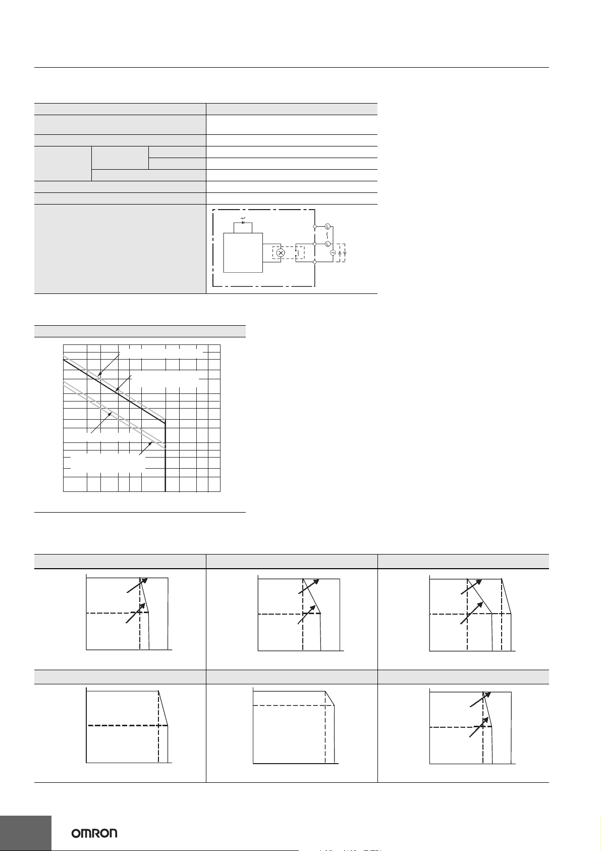
Output Specifications
●Output Specifications for Relay Outputs
Item Specification
Maximum switching capacity
Minimum switching capacity 5 VDC, 10 mA
Service life of
relay
ON delay 15 ms max.
OFF response time 15 ms max.
Electrical
Mechanical 20,000,000 operations
Resistive load 200,000 operations (24 VDC)
Inductive load 70,000 operations (250 VAC, cosφ = 0.4)
250 VAC/2 A (cosφ = 1)
2 A, 24 VDC (4 A/common)
Circuit configuration
Output indicator
Internal
circuits
OUT
OUT
COM
250 VAC, 2A,
24 VDC, 2 A
max.
Estimating the Service Life of Relays
Under normal conditions, the service life of output contacts is as shown above. The service life of relays is as shown in the following diagram as a guideline
CP1E-@@DR-@
1000
700
500
300
200
100
70
)
50
4
30
20
125 VAC cosφ= 0.4
10
Life (x 10
7
5
250 VAC cosφ= 0.4/
3
30 VDC, τ = 7ms
2
1
0.1 0.2 0.3 0.5 0.7 1 2 3 5 7 10
125-VAC resistive load
30-VDC/250-VAC
resistive load
Contact current (A)
Relationship between Continuous Simultaneous ON Rate and Ambient Temperature
There are restrictions on the power supply voltage and output load current imposed by the ambient temperature. Make sure that the power supply
voltage and output load current are within the following ranges.
CP1E-N14DR-D/CP1E-N20DR-D CP1E-N30DR-D CP1E-N40DR-D
100
100%
80%
%
Power voltage
21.6 VDC
50%
Power voltage
20.4 VDC
0%
0%
Ambient temperature
35 45 55˚C
Ambient temperature
50
100%
Power voltage
21.6 VDC
50%
Power voltage
20.4 VDC
0%
100%
Power voltage
50%
Power voltage
55
°C
0%
30 45
Ambient temperature
21.6 VDC
20.4 VDC
Ambient temperature
40
50
55
˚C
˚C
45
55
100%
Power voltage
21.6 VDC
50%
Power voltage
20.4 VDC
0%
Ambient temperature
CP1E-@14DR-A/CP1E-@20DR-A/CP1E-N20DT@-@ CP1E-NA20DR-A CP1E-N60DR-D
100%
50%
0%
Ambient temperature
40
˚C
45
55
˚C
50
55
Note: The above restrictions apply to the relay output load current from the CPU Unit even if Expansion I/O Units are not connected.
22
Page 23
CP1E-E@@D@-@ CP1E-N@@D@-@/NA20D@-@
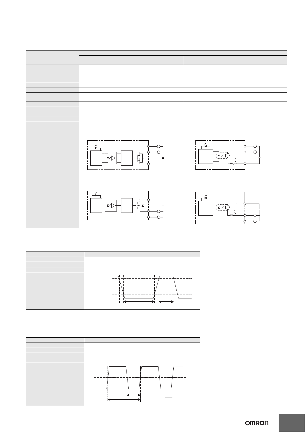
●Output Specifications for Transistor Outputs (Sinking or Sourcing)
Normal Outputs
L
~
L
Specification
24 VDC,
4.5 to 30
VDC
CIO 100.02 to CIO 100.07, CIO 101.00 to CIO 101.07
1.5V max.
1 ms max.
E-type CPU Unit:
Normal outputs CIO 100.00 to CIO 100.03 (sinking)
N/NA-type CPU Unit:
Normal outputs CIO 100.02 to CIO 102.07 (sinking)
E-type CPU Unit:
Normal outputs CIO 100.01 to CIO 100.03 (sourcing)
N/NA-type CPU Unit:
Normal outputs CIO 100.02 to CIO 102.07 (sourcing)
Item
Maximum switching capacity
0.3 A/output, 0.9 A/common *1
4.5 to 30 VDC
CP1E-E10D@-@: 0.9 A/Unit CP1E-N14D@-@: 1.5 A/Unit CP1E-N20D@-@: 1.8 A/Unit CP1E-N30D@-@: 2.7 A/Unit
CP1E-N40D@-@: 3.6 A/Unit CP1E-N60D@-@: 5.4 A/Unit CP1E-NA20D@-@: 1.8 A/Unit
CIO 100.00 and CIO 100.01
Minimum switching capacity 1 mA 4.5 to 30 VDC
Leakage current 0.1mA max.
Residual voltage
E-type CPU Unit: 1.5 V max.
N/NA-type CPU Unit: 0.6 V max.
ON response time 0.1 ms max. 0.1 ms max.
OFF response time
E-type CPU Unit: 1 ms max.
N/NA-type CPU Unit: 0.1 ms max.
Fuse Not provided.
N/NA-type CPU Unit:
Normal outputs CIO 100.00 to CIO 100.01 (sinking)
OUT
OUT
Circuit configuration
Internal
circuits
N/NA-type CPU Unit:
Normal outputs CIO 100.00 to CIO 100.01 (sourcing)
Internal
circuits
COM(–)
and CIO 102.00 to CIO 102.07 *2
Internal
circuits
OUT
OUT
COM(–)
L
~
L
24 VDC,
4.5 to 30
VDC
Internal
circuits
Internal
circuits
COM(+)
OUT
OUT
24 VDC,
4.5 to 30
VDC
L
~
L
Internal
circuits
COM(+)
OUT
OUT
24 VDC,
4.5 to 30
VDC
L
~
L
Note: Do not connect a load to an output terminal or apply a voltage in excess of the maximum switching capacity.
* 1 Also do not exceed 0.9 A for the total for CIO 100.00 to CIO 100.03. (CIO 100.00 to CIO 100.03 is different common.)
* 2 The bits that can be used depend on the model of CPU Unit.
Pulse Outputs (CIO 100.00 and CIO 100.01)
Item Specification
Maximum switching capacity 100 mA/4.5 to 26.4 VDC
Minimum switching capacity 7 mA/4.5 to 26.4 VDC
Maximum output frequency 100 kHz
Output waveform
OFF
ON
90
10
%
%
4μs min.
2μs min.
Note: 1. The load for the above values is assumed to be the resistance load, and does not take into account the impedance for the connecting
cable to the load.
2. Due to distortions in pulse waveforms resulting from connecting cable impedance, the pulse widths in actual operation may be smaller
than the values shown above.
PWM Output (CIO 100.01)
Item Specification
Maximum switching capacity 30 mA/4.5 to 26.4 VDC
Maximum output frequency 32 kHz
PWM output accuracy
For ON duty +1%, .0%:10 kHz output
For ON duty +5%, .0%: 0 to 32 kHz output
OFF
Output waveform
ON
ON
t
T
ON duty=
t
ON
×
100
T
%
23
Page 24
CP1E-E@@D@-@ CP1E-N@@D@-@/NA20D@-@
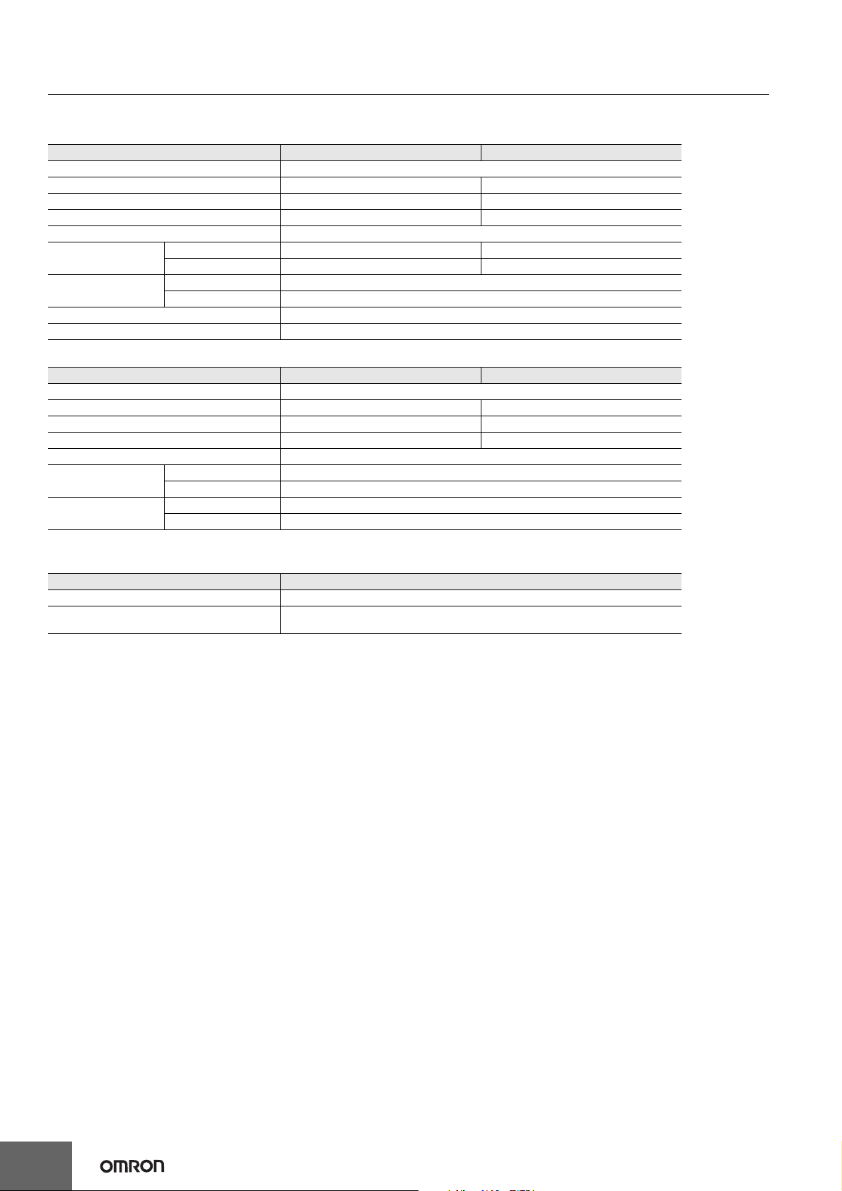
Built-in Analog I/O (NA-type CPU Units)
●Analog Input Specifications
Item Voltage input Current input
Number of inputs 2 inputs (Allocated 2 words: CIO 90 to CIO 91.)
Input signal range 0 to 5 V, 1 to 5 V, 0 to 10 V, or -10 to 10 V 0 to 20 mA or 4 to 20 mA
Max. rated input ±15 V ±30 mA
External input impedance 1 MΩ min. Approx. 250Ω
Resolution 1/6000
Overall accuracy
A/D conversion data
Averaging function Supported (Set for individual inputs in the PLC Setup.)
Open-circuit detection function Supported (Value when disconnected: 8000 hex)
●Analog Output Specifications
Number of outputs 1 output (Allocated 1 word: CIO 190.)
Output signal range 0 to 5 V, 1 to 5 V, 0 to 10 V, or -10 to 10 V 0 to 20 mA or 4 to 20 mA
Allowable external output load resistance 1 kΩ min. 600Ω max.
External input impedance 0.5Ωmax. ---
Resolution 1/6000
Overall accuracy
D/A conversion data
* In 0 to 20 mA mode, accuracy cannot be ensured at 0.2 mA or less.
At 25°C ±0.3% full scale ±0.4% full scale
0 to 55°C ±0.6% full scale ±0.8% full scale
-10 to +10 V F448 to 0BB8 hex FS
Other ranges 0000 to 1770 hex FS
Item Voltage output Current output
At 25°C ±0.4% full scale *
0 to 55°C ±0.8% full scale *
-10 to +10 V F448 to 0BB8 hex FS
Other ranges 0000 to 1770 hex FS
●Shared I/O Specifications
Item Specification
Conversion time 2 ms/point (6 ms total for 2 analog inputs and 1 analog output.)
Isolation method
Photocoupler isolation between analog I/O terminals and internal circuits.
No isolation between analog I/O signals.
24
Page 25
CP1E-E@@D@-@ CP1E-N@@D@-@/NA20D@-@
Specifications of Expansion I/O Units and Expansion Units
Expandable CPU Units
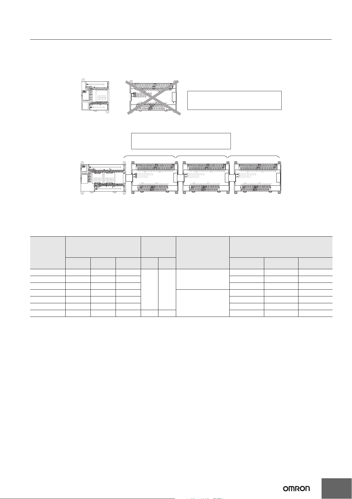
• Expansion I/O Units and Expansion Units cannot be connected to E10/14/20 or N14/20 CPU Units.
• A total of up to three Expansion I/O Units and Expansion Units can be connected to an E30/40, N30/40/60 or NA20 CPU Unit.
●CP1E E10/14/20 or N14/20 CPU Unit
CP-series Expansion Units and Expansion I/O
Units cannot be connected.
●CP1E E30/40, N30/40/60 or NA20 CPU Unit
A total of up to three CP-series Expansion I/O Units
and Expansion Units can be connected.
NCNCNC
COM
01 03 05 07 09 11 01 03 05 07 09 11
NC
00 02 04 06 08 10
CH CH
CH
IN
CH
CH
OUT
CH
CH CH
NC
00 01 02 04 05 07 00 02 04 05 07
NC
COM COM COM COM COM COM03 06 01 03 06
00 02 04 06 08 10
111009080706050403020100
111009080706050403020100
0706050403020100
0706050403020100
40EDR
NCNCNC
COM
01 03 05 07 09 11 01 03 05 07 09 11
NC
00 02 04 06 08 10
00 02 04 06 08 10
CH CH
CH
IN
OUT
EXP
111009080706050403020100
CH
111009080706050403020100
CH
0706050403020100
CH
0706050403020100
CH CH
NC
00 01 02 04 05 07 00 02 04 05 07
NC
COM COM COM COM COM COM03 06 01 03 06
40EDR
NCNCNC
COM
01 03 05 07 09 11 01 03 05 07 09 11
NC
00 02 04 06 08 10
00 02 04 06 08 10
CH CH
CH
IN
OUT
EXP
111009080706050403020100
CH
111009080706050403020100
CH
0706050403020100
CH
0706050403020100
CH CH
NC
00 01 02 04 05 07 00 02 04 05 07
NC
COM COM COM COM COM COM03 06 01 03 06
40EDR
EXP
Connection Methods
Connection cables for the Expansion I/O Units and Expansion Units are used to connect the Units. The length can be extended by using a CP1WCN811 I/O Connection Cable (length: 800 m).
Maximum Number of I/O Points for an Expanded System
Number of inputs: 24
CPU Unit
Built-in I/O on CPU Unit Built-in Analog
Total
Number of
inputs
Number of
outputs
AD DA Total
CP1E-E10D@-@ 10 6 4
CP1E-@14D@-@ 14 8 6 14 8 6
CP1E-@20D@-@ 20 12 8 20 12 8
CP1E-@30D@-@ 30 18 12
None None
CP1E-@40D@-@ 40 24 16 160 96 64
CP1E-N60D@-@ 60 36 24 180 108 72
Total number of
Expansion I/O Units and
Expansion Units that can
be connected
Not possible.
3 Units maximum
Total number of I/O points when three CP1W-40ED@
10 6 4
150 90 60
Number of outputs: 16
Expansion I/O Units are connected
Number of
inputs
Number of
outputs
CP1E-NA20D@-@20 12 8 2 1 140 84 56
Restrictions on External Power Supply Capacity
The following restrictions apply when using the CPU Unit’s external power supply.
●AC-power-supply E30/40, N30/40/60 or NA20 CPU Unit
The power supply capacity is restricted for AC-power-supply E30/40, N30/40/60 or NA20 CPU Units. It may not be possible to use the full 300 mA
of the external power supply, though a CPU Unit can connect any CP-series Expansion I/O Unit or Expansion Unit.
The entire 300 mA from the external power supply can be used if Expansion Units and Expansion I/O Units are not connected.
Refer to the CP1E CPU Unit Hardware Manual (Cat. No. W479) for details.
●AC-power-supply or DC-power-supply E10/14/20, N14/20 CPU Unit
There is no external power supply on AC-power-supply or DC-power-supply E10/14/20, N14/20 CPU Units.
25
Page 26
CP1E-E@@D@-@ CP1E-N@@D@-@/NA20D@-@
r
Specifications of Expansion I/O Units
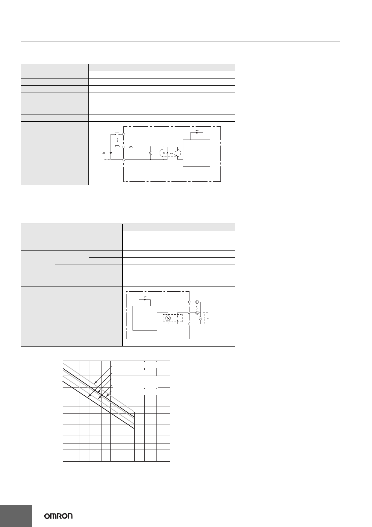
●Input Specifications (CP1W-40EDR/40EDT/40EDT1/20EDR1/20EDT/20EDT1/8ED)
Item Specification
Input voltage 24 VDC +10%/-15%
Input impedance 4.7 kΩ
Input current 5 mA typical
ON voltage 14.4 VDC min.
OFF voltage 5.0 VDC max.
ON delay 1 ms max. *
OFF delay 1 ms max. *
IN
Input LED
Circuit configuration
COM
4.7 kΩ
IN
750 Ω
Internal
circuits
Note: Do not apply voltage in excess of the rated voltage to the input terminal.
* The response time is the hardware delay value. The delay set in the PLC Setup (0 to 32 ms, default: 8 ms) must be added to this value. For the
CP1W-40EDR/EDT/EDT1, a fixed value of 16 ms must be added.
●Output Specifications
Relay Outputs (CP1W-40EDR/32ER/20EDR1/16ER/8ER)
Item Specification
Max. switching capacity
Min. switching capacity 5 VDC, 10 mA
Service life of
relay
(See note.)
ON delay 15 ms max.
OFF delay 15 ms max.
Electrical
Mechanical 20,000,000 operations
Resistive load 150,000 operations (24 VDC)
Inductive load 100,000 operations (240 VAC, cosφ = 0.4)
2 A, 250 VAC (cosφ = 1),
2 A, 24 VDC (4 A/common)
Output LED
v
OUT
Circuit configuration
Note: 1. Estimating the Service Life of Relays
The service life of output contacts is as shown in the following diagram.
300
200
100
50
)
4
30
20
Life (× 10
10
5
3
2
0.1
0.2 0.3 0.5 0.7 1 235
120 VAC resistive load
24 VDC τ = 7 ms
120 VAC cosφ = 0.4
240 VAC cosφ = 0.4
24 VDC/240 VAC resistive load
Contact current (A)
Internal
circuits
OUT
COM
Maximum
250 VAC: 2 A
24 VDC: 2 A
Switching rate: 1,800 operations/hou
26
Page 27
CP1E-E@@D@-@ CP1E-N@@D@-@/NA20D@-@
C
p
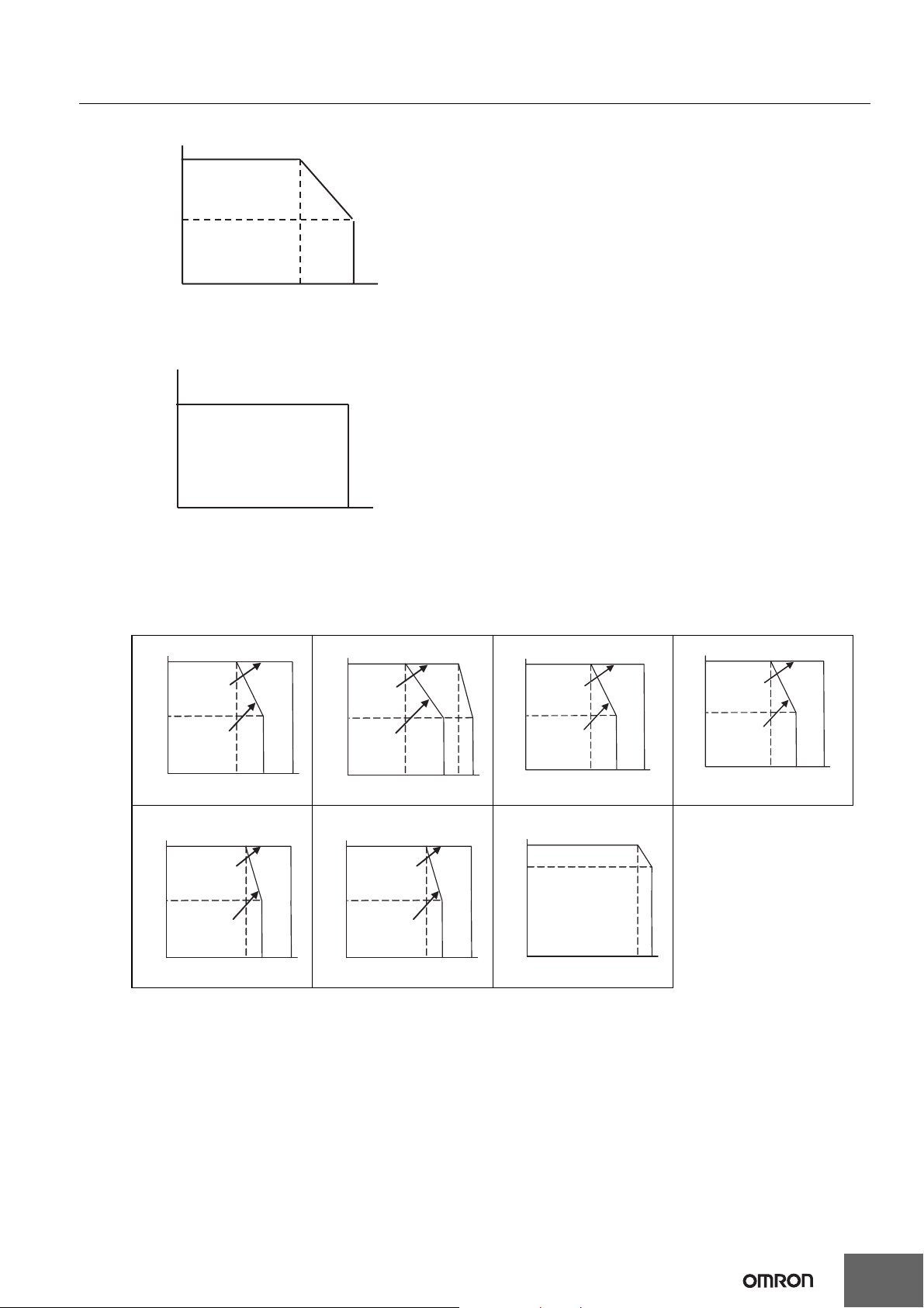
2. Restrictions of CP1W-16ER/32ER
Limit the output load current to satisfy the following derating curve.
100
50
Output load current(%)
0
43
Ambient temperature(˚C)
3. CP1W-32ER’s maximum number of simultaneously ON output points is 24 (75%).
Relation between Number of ON Outputs and Ambient Temperature (CP1W-32ER)
75
Number of inputs
ON simultaneously (%)
0
Ambient temperature (˚C)
55
55
4. According to the ambient temperature, there are restrictions on power supply voltage and output load current for the CPU Units
connected with the Expansion I/O Units (CP1W-8ER/16ER/20EDR1/32ER/40EDR). Use the PLC in the range of the power supply
voltage and output load current as show below.
The ambient temperature is restricted for the power-supply CPU Units (CP1E-N/NA@@@@-@). Derating curve of the output load current
for Expansion I/O Units (CP1W-8ER/16ER/20EDR1/32ER/40EDR).
Connected to CP1E-N30DR-D
100%
Power voltage:
21.6 VDC
50%
Power voltage:
20.4 VDC
0%
4535
Ambient temperature
Connected to
CP1E-N60DR-D/CP1E-N60DT@-D
100%
Power voltage:
21.6 VDC
50%
Power voltage:
20.4 VDC
0%
40
Ambient temperature
Connected to CP1E-N40DR-D Connected to CP1E-N30DT@-D Connected to CP1E-N40DT@-D
100%
Power
voltage:
21.6 VDC
50%
Power
voltage:
20.4 VDC
0%
°
55
30
Ambient temperature
100%
Power voltage:
21.6 VDC
50%
Power voltage:
20.4 VDC
0%
55
°C45
50
Ambient tem
erature
100%
Power
voltage:
21.6 VDC
50%
Power
voltage:
20.4 VDC
0%
°C4535
55
Ambient temperature
Connected to CP1E-NA20DT@-D Connected to CP1E-NA20DR-A
100%
Power voltage:
21.6 VDC
50%
Power voltage:
20.4 VDC
0%
55
°C45
40
Ambient temperature
100%
80%
0%
55
°C45
55
Ambient temperature
50
°C
°C4535
55
27
Page 28
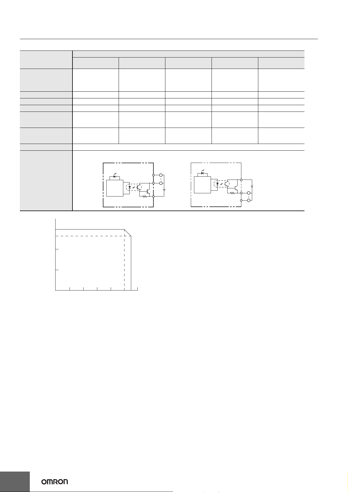
CP1E-E@@D@-@ CP1E-N@@D@-@/NA20D@-@
●Transistor Outputs (Sinking or Sourcing)
Item
Max. switching capacity
*1
CP1W-40EDT
CP1W-40EDT1
4.5 to 30 VDC
0.3 A/output
0.9 A/common
3.6 A/Unit
CP1W-32ET
CP1W-32ET1
4.5 to 30 VDC
0.3 A/output
0.9 A/common
7.2 A/Unit
Leakage current 0.1 mA max. 0.1 mA max. 0.1 mA max. 0.1 mA max. 0.1 mA max.
Residual voltage 1.5 V max. 1.5 V max. 1.5 V max. 1.5 V max. 1.5 V max.
ON delay 0.1 ms max. 0.1 ms max. 0.1 ms. 0.1 ms max. 0.1 ms max.
OFF delay
Max. number of
Simultaneously ON
Points of Output
1 ms max.
24 VDC +10%/-5%
5 to 300 mA
16 pts (100%) 24 pts (75%) 8 pts (100%) 16 pts (100%) 8 pts (100%)
1 ms max.
24 VDC +10%/-5%
5 to 300 mA
Fuse *2 1 fuse/common
Sinking Outputs Sourcing Outputs
Circuit configuration
Output LED
Internal
circuits
OUT
OUT
COM (−)
Specification
CP1W-20EDT
CP1W-20EDT1
24 VDC +10%/-5%
0.3 A/output
0.9 A/common
1.8 A/Unit
1 ms max.
24 VDC +10%/-5%
5 to 300 mA
L
L
24 VDC/4.5
to 30 VDC
Output LED
Internal
circuits
CP1W-16ET
CP1W-16ET1
4.5 to 30 VDC
0.3 A/output
0.9 A/common
3.6 A/Unit
1 ms max.
24 VDC +10%/-5%
5 to 300 mA
OUT
OUT
COM (+)
L
L
24 VDC/4.5
to 30 VDC
CP1W-8ET
CP1W-8ET1
4.5 to 30 VDC
0.3 A/output
0.9 A/common
1.8 A/Unit
1 ms max.
24 VDC +10%/-5%
5 to 300 mA
*1 If the ambient temperature is maintained below 50°C, up to 0.9 A/common can be used.
(A)
0.9
0.8
Total current for common
0
Ambient temperature
50 55
(°C)
*2 The fuse cannot be replaced by the user. Replace the Unit if the fuse breaks due to an short-circuit or overcurrent.
*3 Do not connect a load to an output terminal or apply a voltage in excess of the maximum switching capacity.
28
Page 29
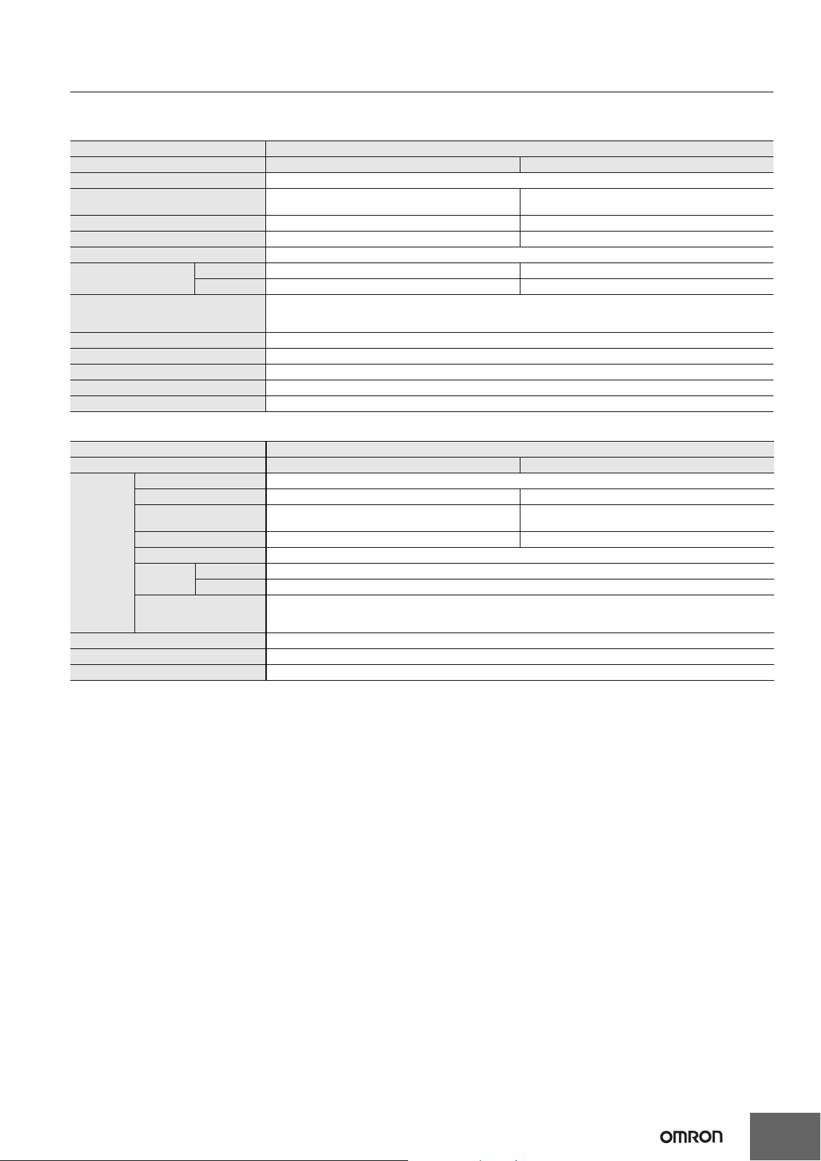
CP1E-E@@D@-@ CP1E-N@@D@-@/NA20D@-@
Specifications of Expansion Units
●Analog Input Units
Model CP1W-AD041
Item Voltage Input Current Input
Number of inputs 4 inputs (4 words allocated)
Input signal range
Max. rated input ±15 V ±30 mA
External input impedance 1 MΩ min. Approx. 250 Ω
Resolution 1/6000 (full scale)
Overall accuracy
A/D conversion data
Averaging function Supported (Set in output words n+1 and n+2.)
Open-circuit detection function Supported
Conversion time 2 ms/point (8 ms/all points)
Isolation method Photocoupler isolation between analog I/O terminals and internal circuits. No isolation between analog I/O signals.
Current consumption 5 VDC: 100 mA max.; 24 VDC: 90 mA max.
25°C 0.3% full scale 0.4% full scale
0 to 55°C 0.6% full scale 0.8% full scale
●Analog Output Units
Model CP1W-DA041
Item Voltage Output Current Output
Number of outputs 4 outputs (4 words allocated)
Output signal range 1 to 5 VDC, 0 to 10 VDC, or –10 to 10 VDC 0 to 20 mA or 4 to 20 mA
External output allowable
load resistance
Analog
output
section
Conversion time 2 ms/point (8 ms/all points)
Isolation method Photocoupler isolation between analog I/O terminals and internal circuits. No isolation between analog I/O signals.
Current consumption 5 VDC: 80 mA max.; 24 VDC: 124 mA max.
External output impedance 0.5 Ω max. ---
Resolution 1/6000 (full scale)
Overall
accuracy
D/A conversion data
25°C 0.4% full scale
0 to 55°C 0.8% full scale
0 to 5 VDC, 1 to 5 VDC,
0 to 10 VDC, or –10 to 10 VDC
16-bit binary (4-digit hexadecimal)
Full scale for –10 to 10 V: F448 to 0BB8 Hex
Full scale for other ranges: 0000 to 1770 Hex
2 kΩ min. 350 Ω max.
16-bit binary (4-digit hexadecimal)
Full scale for –10 to 10 V: F448 to 0BB8 Hex
Full scale for other ranges: 0000 to 1770 Hex
0 to 20 mA or 4 to 20 mA
29
Page 30
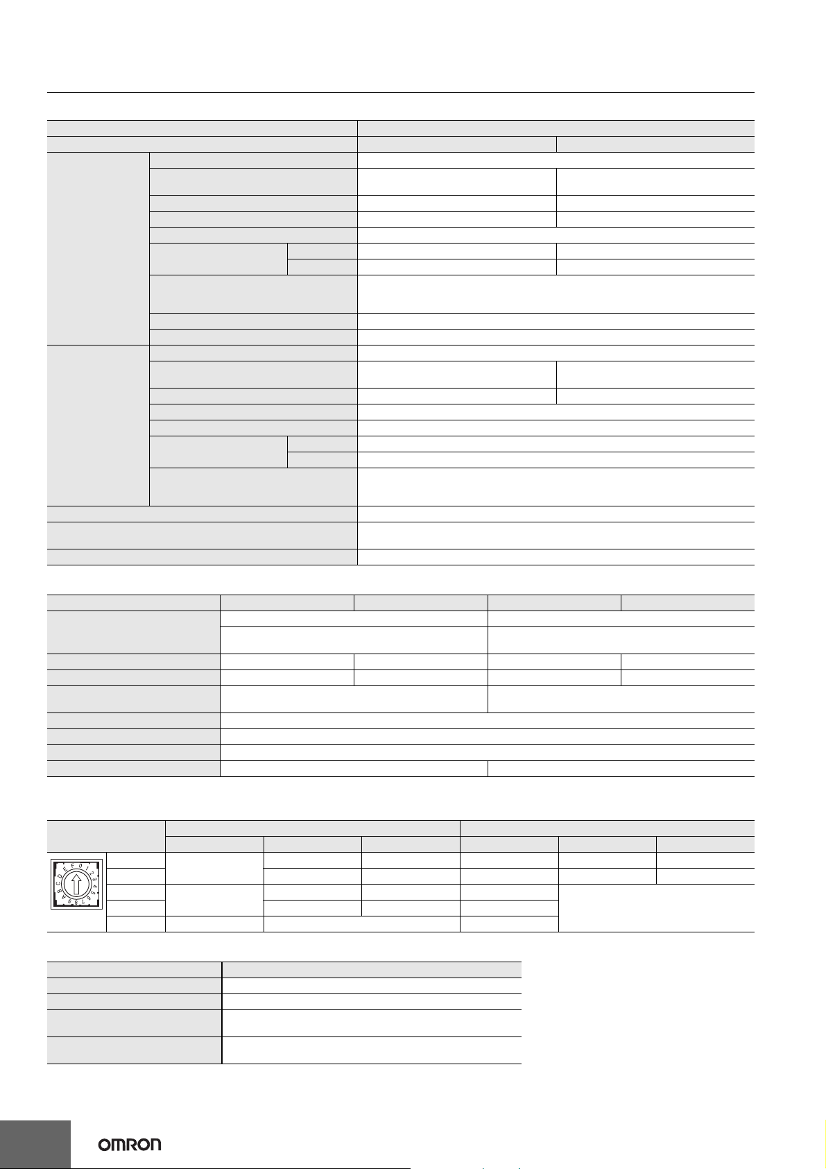
CP1E-E@@D@-@ CP1E-N@@D@-@/NA20D@-@
●Analog I/O Units
Model CP1W-MAD11
Item Voltage I/O Current I/O
Number of inputs 2 inputs (2 words allocated)
Input signal range
Max. rated input ±15 V ±30 mA
External input impedance 1 MΩ min. Approx. 250 Ω
Analog Input
Section
Analog Output
Section
Conversion time 2 ms/point (6 ms/all points)
Isolation method
Current consumption 5 VDC: 83 mA max., 24 VDC: 110 mA max.
Resolution 1/6000 (full scale)
Overall accuracy
A/D conversion data
Averaging function Supported (Settable for individual inputs via DIP switch)
Open-circuit detection function Supported
Number of outputs 1 output (1 word allocated)
Output signal range
Allowable external output load resistance 1 kΩ min. 600 Ω max.
External output impedance 0.5 Ω max.
Resolution 1/6000 (full scale)
Overall accuracy
Set data (D/A conversion)
25°C 0.3% full scale 0.4% full scale
0 to 55°C 0.6% full scale 0.8% full scale
25°C 0.4% full scale
0 to 55°C 0.8% full scale
0 to 5 VDC, 1 to 5 VDC,
0 to 10 VDC, or −10 to 10 VDC
16-bit binary (4-digit hexadecimal)
Full scale for −10 to 10 V: F448 to 0BB8 hex
Full scale for other ranges: 0000 to 1770 hex
1 to 5 VDC, 0 to 10 VDC, or
−10 to 10 VDC,
16-bit binary (4-digit hexadecimal)
Full scale for −10 to 10 V: F448 to 0BB8 hex
Full scale for other ranges: 0000 to 1770 hex
Photocoupler isolation between analog I/O terminals and internal circuits.
No isolation between analog I/O signals.
0 to 20 mA or 4 to 20 mA
0 to 20 mA or 4 to 20 mA
●Temperature Sensors Units
Item CP1W-TS001 CP1W-TS002 CP1W-TS101 CP1W-TS102
Temperature sensors
Number of inputs 2424
Allocated input words 2424
Accuracy
Conversion time 250 ms for 2 or 4 input points
Converted temperature data 16-bit binary data (4-digit hexadecimal)
Isolation Photocouplers between all temperature input signals
Current consumption 5 VDC: 40 mA max., 24 VDC: 59 mA max. 5 VDC: 54 mA max., 24 VDC: 73 mA max.
Thermocouples Platinum resistance thermometer
Switchable between K and J, but same type must be used for
all inputs.
(The larger of ±0.5% of converted value or ±2°C) ±1 digit
max. *
Switchable between Pt100 and JPt100, but same type must
be used for all inputs.
(The larger of ±0.5% of converted value or ±1°C) ±1 digit
max.
* Accuracy for a K-type sensor at -100°C or less is ±4°C ±1 digit max.
The rotary switch is used to set the temperature range.
Setting
0
1 0.0 to 500.0 0.0 to 900.0 JPt100 −200.0 to 650.0 −300.0 to 1,200.0
2
4 to F --- Cannot be set. ---
Input type Range (°C) Range (°F) Input type Range (°C) Range (°F)
K
J
CP1W-TS001/TS002 CP1W-TS101/TS102
−200 to 1,300 −300 to 2,300 Pt100 −200.0 to 650.0 −300.0 to 1,200.0
−100 to 850 −100 to 1,500 ---
Cannot be set.3 0.0 to 400.0 0.0 to 750.0 ---
●CompoBus/S I/O Link Unit
Model number CP1W-SRT21
Master/slave CompoBus/S Slave
Number of I/O points 8 input points, 8 output points
Number of words allocated in CPU
Unit I/O memory
Node number setting
1 input word, 1 output word
Set using the DIP switch
(Set before turning on the CPU Unit’s power supply.)
30
Page 31
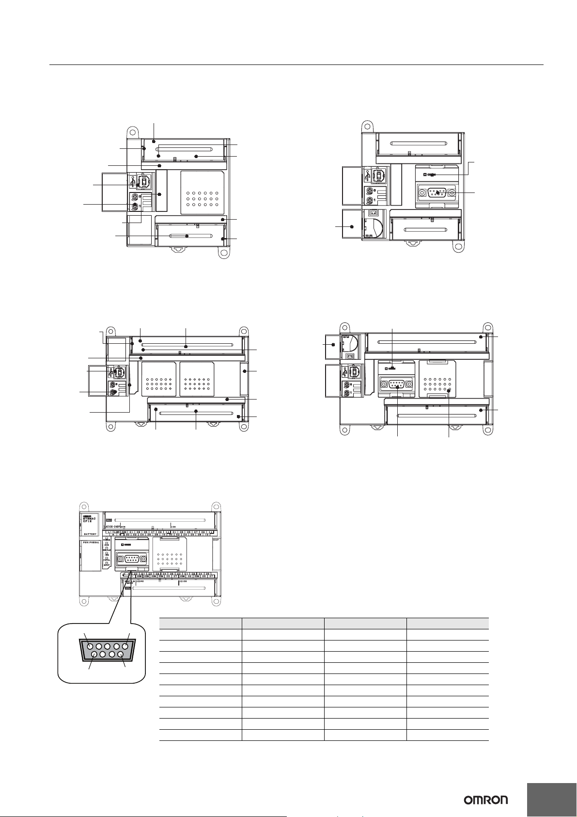
CP1E-E@@D@-@ CP1E-N@@D@-@/NA20D@-@
External Interfaces
The CP1E CPU Units provide the following external interfaces.
E10/14/20 or N14/20 CPU Units
E-type N-type
Power supply input terminals
Input terminal block
Input indicators
Peripheral
USB port
Analog
adjusters
Operation indicators
Output terminals
Ground terminal
Input terminals
Output indicators
Output terminal
block
Note: Terminal Block (Fixed)
E30/40, N30/40/60 or NA20 CPU Units
E-type N-type/NA-type
Power supply
input terminals
Input terminal
block
Input
indicators
Peripheral
USB port
Analog
adjusters
Operation
indicators
External power
supply
Note: Terminal Block (Fixed)
Input terminals
Output terminals
Ground
terminal
Expansion
I/O Unit
connector
Output
indicators
Output
terminal
block
Battery
cover
Battery
cover
Built-in RS-232C communications
status indicator
Built-in RS-232C
port
Serial Option
Board slot
Built-in RS-232C
communications
status indicator
Built-in
RS-232C port
Analog input
terminal
(NA-type only)
Analog output
terminals
(NA-type only)
Built-in RS-232C Port for N/NA-type CPU Units
●RS-232C Connector
5
9
1
6
1 FG Frame ground --
2 SD (TXD) Send data Output
3 RD (RXD) Receive data Input
4 RS (RTS) Request to send Output
5 CS (CTS) Clear to send Input
6 5 V Power supply --
7 DR (DSR) Data set ready Input
8 ER (DTR) Data terminal ready Output
9 SG (0 V) Signal ground --
Connector hood FG Frame Ground --
Note:
Pin Abbr. Signal name Signal direction
Do not use the 5-V power from pin 6 of the RS-232C port for anything but CJ1W-CIF11 RS-422A Conversion
Adapter, NT-AL001 RS-232C/RS-422A Conversion Adapter and NV3W-M
The external device or the CPU Unit may be damaged.
@
20L Programmable Terminal.
31
Page 32
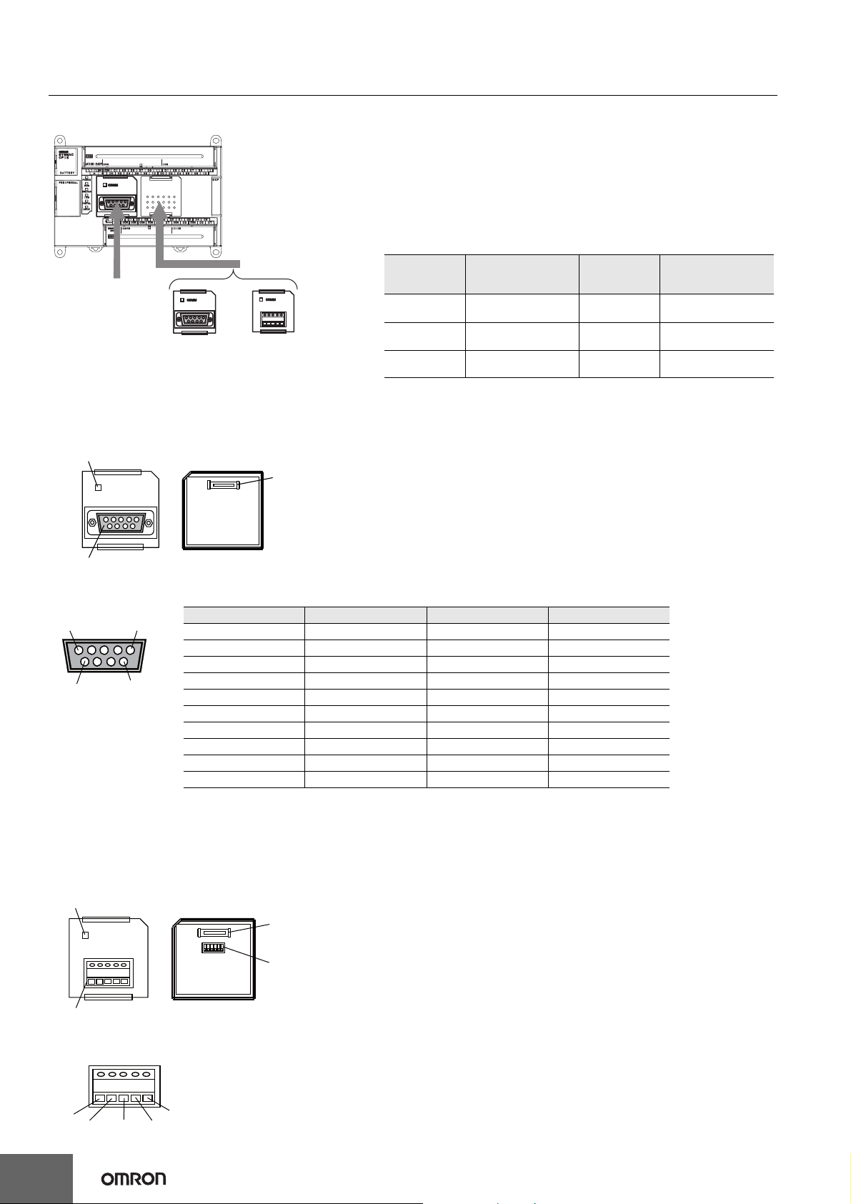
CP1E-E@@D@-@ CP1E-N@@D@-@/NA20D@-@
Optional Serial Communications Board for N30/40/60 or NA20 CPU Units
CP1E N30/40/60
or NA20 CPU Units
Built-in
RS-232C port
CP1W-CIF01
RS-232C Option
Board
CP1W-CIF11/12
RS-422A/485 Option
Board
CP1W-CIF01 RS-232C Option Board
Front Back
Communications Status Indicator
COMM
RS-232 Connector
●RS-232C Connector
5
9
1
6
1 FG Frame ground --
2 SD (TXD) Send data Output
3 RD (RXD) Receive data Input
4 RS (RTS) Request to send Output
5 CS (CTS) Clear to send Input
6 5 V Power supply --
7 DR (DSR) Data set ready Input
8 ER (DTR) Data terminal ready Output
9 SG (0 V) Signal ground --
Connector hood FG Frame Ground --
Note: Do not use the 5-V power from pin 6 of the RS-232C port for anything but CJ1W-CIF11 RS-422A Conversion
Pin Abbr. Signal name Signal direction
Adapter, NT-AL001 RS-232C/RS-422A Conversion Adapter and NV3W-M
The external device or the CPU Unit may be damaged.
CPU Unit Connector
Model number Port
CP1W-CIF01 One RS-232C port 15 m
CP1W-CIF11
CP1W-CIF12
One RS-422A/485 port
(not isolated)
One RS-422A/485 port
(isolated)
transmission
50 m
500 m
@
Maximum
distance
20L Programmable Terminal.
Connection method
Connector
(D-sub, 9 pin female)
Terminal block
(using ferrules)
Terminal block
(using ferrules)
CP1W-CIF11/CIF12 RS-422A/485 Option Board
Front Back
Communications Status Indicator
COMM
RDA- RDB+ SDA- SDB+ FG
CPU Unit
Connector
DIP Switch for
Operation Settings
RS-422A/485 Connector
●RS-422A/485 Terminal Block
Tighten the terminal block screws
to a torque of 0.28 N·m.
RDA-
RDB+
SDA- SDB+
FG
32
Page 33
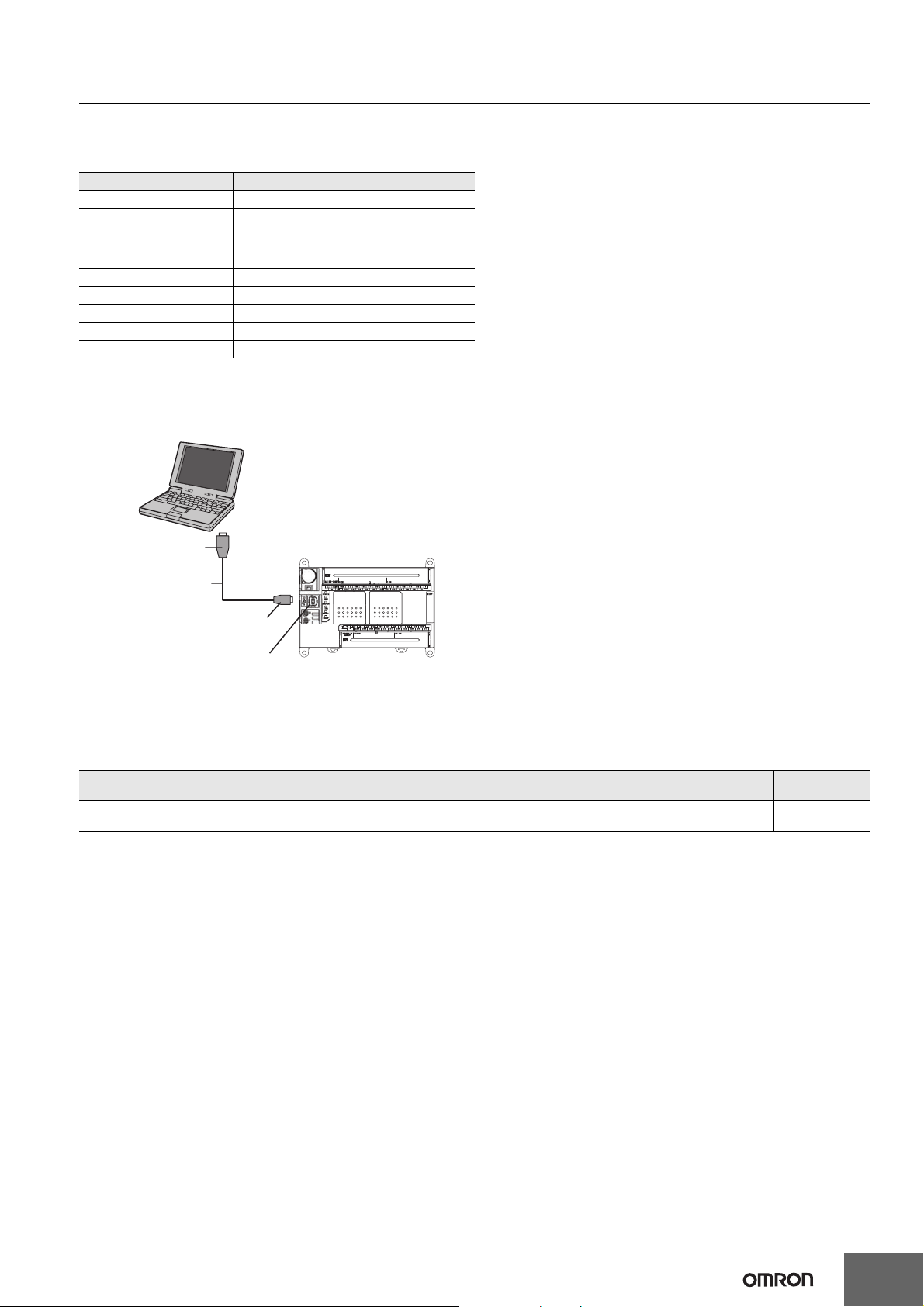
CP1E-E@@D@-@ CP1E-N@@D@-@/NA20D@-@
Connecting to Support Software
Operating Environment and System Configuration
The following system is required to operate the CX-Programmer. Make sure your system provides the following conditions and has the necessary
components.
Item Description
Supported computer IBM PC/AT or equivalent
CD-ROM or DVD-ROM drive One or more
Supported Operating Systems
CPU Pentium II 333 MHz or faster
RAM 256 MB min. 512 MB or more recommended
Available hard disk space 600 MB min.
Display 800 x 600 SVGA min.
PLC and connection port USB port
Connecting Methods
Using commercially available USB cable, connect the CX-Programmer to the peripheral USB port on the CPU Unit.
CX-Programmer
Windows 7, Windows Vista, Windows XP,
Windows 2000 (Service Pack 4 or later)
(except 64-bit edition)
USB port
A connector
Commercially available
USB cable *
B connector
Peripheral USB port
(Conforming to USB 2.0, B connector)
Note: The CX-Programmer cannot be used if it is connected to the built-in RS-232C port or serial option port of a CP1E CPU Unit.
* Commercially available USB cable: 5 m max., for USB 2.0.
CP1E CPU Unit
Connecting Cable
Use the following cable to connect the CP1E CPU Unit to the computer running the Support Software.
Port at Unit Port at computer
Peripheral USB port
(Conforming to USB 2.0, B connector)
USB port USB 2.0 (or 1.1)
Network type
(communications mode)
Model numbers Length
Commercially available USB cable
(A connector - B connector)
Less than 5 m
33
Page 34
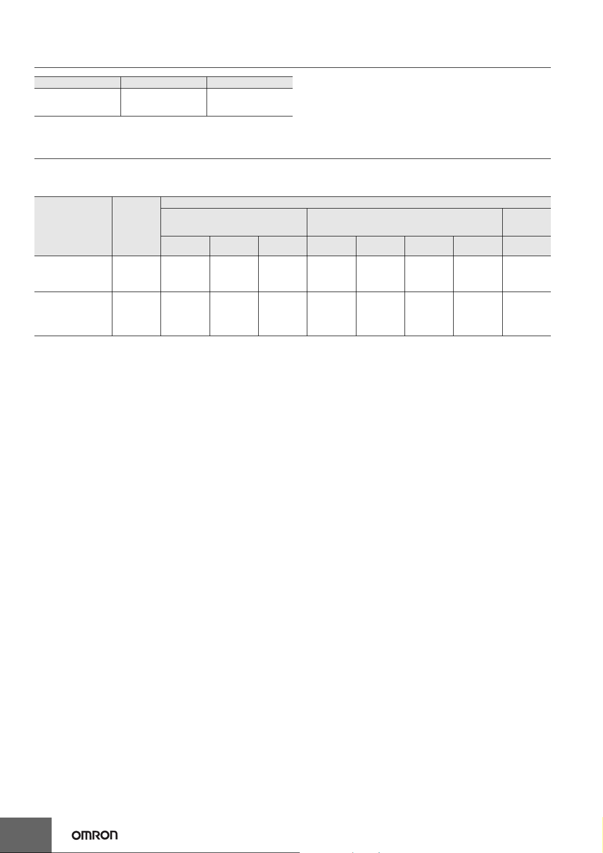
CP1E-E@@D@-@ CP1E-N@@D@-@/NA20D@-@
Unit Versions
Units Model numbers Unit version
CP1E CPU Units
CP1E-E@@D@-@
CP1E-N@@D@-@
CP1E-NA@@D@-@
Unit version 1.@
Unit Versions and Programming Devices
The following tables show the relationship between unit versions and CX-Programmer versions.
Unit Versions and Programming Devices
Required Programming Device *
CPU Unit Functions
Ver.8.1 or
CP1E-E10D@-@
CP1E-@14D@-@
CP1E-N60D@-@
CP1E-NA20D@-@
CP1E-E20/30/40D@-A
CP1E-N20/30/40D@-@
Unit version
1.@ functions
Unit version
1.@ functions
Not support. Not support.
Not support.
* A Programming Console cannot be used.
CX-Programmer Micro PLC Edition CX-Programmer
lower
Ver.8.2
Yes
Does not
support
Smart Input
function.
Ver.9.03
or higher
Yes
Supports
Smart Input
function.
Yes
Supports
Smart Input
function.
Ver.8.1 or
lower
Not support. Not support. Not support.
Yes
Not support.
Does not
support
Smart Input
function.
Ver.8.2 Ver.9.0
Yes
Supports
Smart Input
function.
Ver.9.03
or higher
Yes
Supports
Smart Input
function.
Yes
Supports
Smart Input
function.
CX-
Programmer
for CP1E
Ver.1.0
Not support.
Yes
Supports
Smart Input
function.
34
Page 35
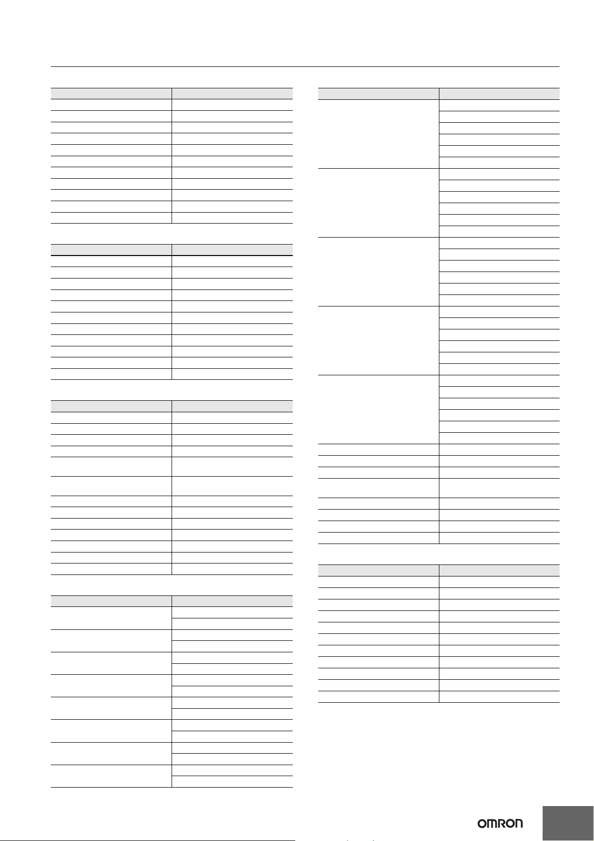
Programming Instructions
CP1E-E@@D@-@ CP1E-N@@D@-@/NA20D@-@
Sequence Input Instructions
Instruction Mnemonic
LOAD LD
LOAD NOT LD NOT
AND AND
AND NOT AND NOT
OR OR
OR NOT OR NOT
AND LOAD AND LD
OR LOAD OR LD
NOT NOT
CONDITION ON UP
CONDITION OFF DOWN
Sequence Output Instructions
Instruction Mnemonic
OUTPUT OUT
OUTPUT NOT OUT NOT
KEEP KEEP
DIFFERENTIATE UP DIFU
DIFFERENTIATE DOWN DIFD
SET SET
RESET RSET
MULTIPLE BIT SET SETA
MULTIPLE BIT RESET RSTA
SINGLE BIT SET SETB
SINGLE BIT RESET RSTB
Sequence Output Instructions
Instruction Mnemonic
END END
NO OPERATION NOP
INTERLOCK IL
INTERLOCK CLEAR ILC
MULTI-INTERLOCK
DIFFERENTIATION HOLD
MULTI-INTERLOCK
DIFFERENTIATION RELEASE
MULTI-INTERLOCK CLEAR MILC
JUMP JMP
JUMP END JME
CONDITIONAL JUMP CJP
FOR LOOP FOR
BREAK LOOP BREAK
NEXT LOOP NEXT
MILH
MILR
Timer and Counter Instructions
Instruction Mnemonic
TIMER
COUNTER
HIGH-SPEED TIMER
ONE-MS TIMER
ACCUMULATIVE TIMER
LONG TIMER
REVERSIBLE COUNTER
RESET TIMER/COUNTER
TIM
TIMX
CNT
CNTX
TIMH
TIMHX
TMHH
TMHHX
TTIM
TTIMX
TIML
TIMLX
CNTR
CNTRX
CNR
CNRX
Comparison Instructions
Instruction Mnemonic
LD,AND,OR+=
LD,AND,OR+<>
Input Comparison Instructions
(unsigned)
Input Comparison Instructions
(double, unsigned)
Input Comparison Instructions
(signed)
Input Comparison Instructions
(double, signed)
Time Comparison Instructions
COMPARE CMP
DOUBLE COMPARE CMPL
SIGNED BINARY COMPARE CPS
DOUBLE SIGNED BINARY
COMPARE
TABLE COMPARE TCMP
UNSIGNED BLOCK COMPARE BCMP
AREA RANGE COMPARE ZCP
DOUBLE AREA RANGE COMPARE ZCPL
LD,AND,OR+<
LD,AND,OR+<=
LD,AND,OR+>
LD,AND,OR+>=
LD,AND,OR+=+L
LD,AND,OR+<>+L
LD,AND,OR+<+L
LD,AND,OR+<=+L
LD,AND,OR+>+L
LD,AND,OR+>=+L
LD,AND,OR+=+S
LD,AND,OR+<>+S
LD,AND,OR+<+S
LD,AND,OR+<=+S
LD,AND,OR+>+S
LD,AND,OR+>=+S
LD,AND,OR+=+SL
LD,AND,OR+<>+SL
LD,AND,OR+<+SL
LD,AND,OR+<=+SL
LD,AND,OR+>+SL
LD,AND,OR+>=+SL
=DT
<>DT
<DT
<=DT
>DT
>=DT
CPSL
Data Movement Instructions
Instruction Mnemonic
MOVE MOV
DOUBLE MOVE MOVL
MOVE NOT MVN
MOVE BIT MOVB
MOVE DIGIT MOVD
MULTIPLE BIT TRANSFER XFRB
BLOCK TRANSFER XFER
BLOCK SET BSET
DATA EXCHANGE XCHG
SINGLE WORD DISTRIBUTE DIST
DATA COLLECT COLL
35
Page 36
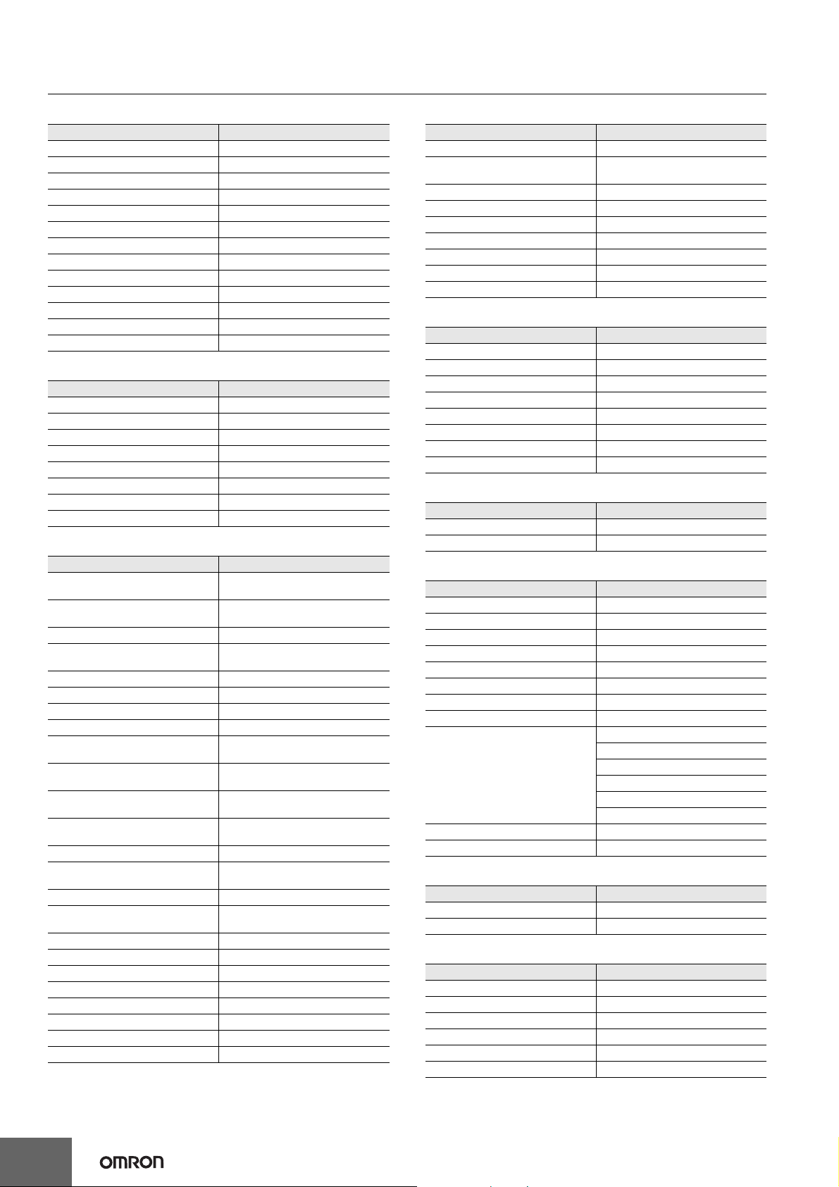
CP1E-E@@D@-@ CP1E-N@@D@-@/NA20D@-@
Data Shift Instructions
Instruction Mnemonic
SHIFT REGISTER SFT
REVERSIBLE SHIFT REGISTER SFTR
WORD SHIFT WSFT
ARITHMETIC SHIFT LEFT ASL
ARITHMETIC SHIFT RIGHT ASR
ROTATE LEFT ROL
ROTATE RIGHT ROR
ONE DIGIT SHIFT LEFT SLD
ONE DIGIT SHIFT RIGHT SRD
SHIFT N-BITS LEFT NASL
DOUBLE SHIFT N-BITS LEFT NSLL
SHIFT N-BITS RIGHT NASR
DOUBLE SHIFT N-BITS RIGHT NSRL
Increment/Decrement Instructions
Instruction Mnemonic
INCREMENT BINARY ++
DOUBLE INCREMENT BINARY ++L
DECREMENT BINARY --
DOUBLE DECREMENT BINARY --L
INCREMENT BCD ++B
DOUBLE INCREMENT BCD ++BL
DECREMENT BCD --B
DOUBLE DECREMENT BCD --BL
Symbol Math Instructions
Instruction Mnemonic
SIGNED BINARY ADD WITHOUT
CARRY
DOUBLE SIGNED BINARY ADD
WITHOUT CARRY
SIGNED BINARY ADD WITH CARRY
DOUBLE SIGNED BINARY ADD
WITH CARRY
BCD ADD WITHOUT CARRY +B
DOUBLE BCD ADD WITHOUT CARRY
BCD ADD WITH CARRY +BC
DOUBLE BCD ADD WITH CARRY +BCL
SIGNED BINARY SUBTRACT
WITHOUT CARRY
DOUBLE SIGNED BINARY
SUBTRACT WITHOUT CARRY
SIGNED BINARY SUBTRACT WITH
CARRY
DOUBLE SIGNED BINARY
SUBTRACT WITH CARRY
BCD SUBTRACT WITHOUT CARRY -B
DOUBLE BCD SUBTRACT
WITHOUT CARRY
BCD SUBTRACT WITH CARRY -BC
DOUBLE BCD SUBTRACT WITH
CARRY
SIGNED BINARY MULTIPLY *
DOUBLE SIGNED BINARY MULTIPLY
BCD MULTIPLY *B
DOUBLE BCD MULTIPLY *BL
SIGNED BINARY DIVIDE /
DOUBLE SIGNED BINARY DIVIDE /L
BCD DIVIDE /B
DOUBLE BCD DIVIDE /BL
+
+L
+C
+CL
+BL
-
-L
-C
-CL
-BL
-BCL
*L
Conversion Instructions
Instruction Mnemonic
BCD-TO-BINARY BIN
DOUBLE BCD-TO-DOUBLE
BINARY
BINARY-TO-BCD BCD
DOUBLE BINARY-TO-DOUBLE BCD
2’S COMPLEMENT NEG
DATA DECODER MLPX
DATA ENCODER DMPX
ASCII CONVERT ASC
ASCII TO HEX HEX
BINL
BCDL
Logic Instructions
Instruction Mnemonic
LOGICAL AND ANDW
DOUBLE LOGICAL AND ANDL
LOGICAL OR ORW
DOUBLE LOGICAL OR ORWL
EXCLUSIVE OR XORW
DOUBLE EXCLUSIVE OR XORL
COMPLEMENT COM
DOUBLE COMPLEMENT COML
Special Math Instructions
Instruction Mnemonic
ARITHMETIC PROCESS APR
BIT COUNTER BCNT
Floating-point Math Instructions
Instruction Mnemonic
FLOATING TO 16-BIT FIX
FLOATING TO 32-BIT FIXL
16-BIT TO FLOATING FLT
32-BIT TO FLOATING FLTL
FLOATING-POINT ADD +F
FLOATING-POINT SUBTRACT -F
FLOATING-POINT DIVIDE /F
FLOATING-POINT MULTIPLY *F
LD, AND, OR+=F
LD, AND, OR+<>F
Floating Symbol Comparison
FLOATING- POINT TO ASCII FSTR
ASCII TO FLOATING-POINT FVAL
LD, AND, OR+<F
LD, AND, OR+<=F
LD, AND, OR+>F
LD, AND, OR+>=F
Table Data Processing Instructions
Instruction Mnemonic
SWAP BYTES SWAP
FRAME CHECKSUM FCS
Data Control Instructions
Instruction Mnemonic
PID CONTROL WITH AUTOTUNING PIDAT
TIME-PROPORTIONAL OUTPUT TPO
SCALING SCL
SCALING 2 SCL2
SCALING 3 SCL3
AVERAGE AVG
36
Page 37
CP1E-E@@D@-@ CP1E-N@@D@-@/NA20D@-@
Subroutine Instructions
Instruction Mnemonic
SUBROUTINE CALL SBS
SUBROUTINE ENTRY SBN
SUBROUTINE RETURN RET
Interrupt Control Instructions
Instruction Mnemonic
SET INTERRUPT MASK MSKS
CLEAR INTERRUPT CLI
DISABLE INTERRUPTS DI
ENABLE INTERRUPTS EI
High-speed Counter and Pulse Output
Instructions
Instruction Mnemonic
MODE CONTROL INI
HIGH-SPEED COUNTER PV READ PRV
COMPARISON TABLE LOAD CTBL
SPEED OUTPUT SPED
SET PULSES PULS
PULSE OUTPUT PLS2
ACCELERATION CONTROL ACC
ORIGIN SEARCH ORG
PULSE WITH VARIABLE DUTY
FACTOR
PWM
Step Instructions
Instruction Mnemonic
STEP DEFINE STEP
STEP START SNXT
I/O Unit Instructions
Instruction Mnemonic
I/O REFRESH IORF
7-SEGMENT DECODER SDEC
DIGITAL SWITCH INPUT DSW
MATRIX INPUT MTR
7-SEGMENT DISPLAY OUTPUT 7SEG
Serial Communications Instructions
Instruction Mnemonic
TRANSMIT TXD
RECEIVE RXD
Clock Instructions
Instruction Mnemonic
CALENDAR ADD CADD
CALENDAR SUBTRACT CSUB
CLOCK ADJUSTMENT DATE
Failure Diagnosis Instructions
Instruction Mnemonic
FAILURE ALARM FAL
SEVERE FAILURE ALARM FALS
Other Instructions
Instruction Mnemonic
SET CARRY STC
CLEAR CARRY CLC
EXTEND MAXIMUM CYCLE TIME WDT
37
Page 38
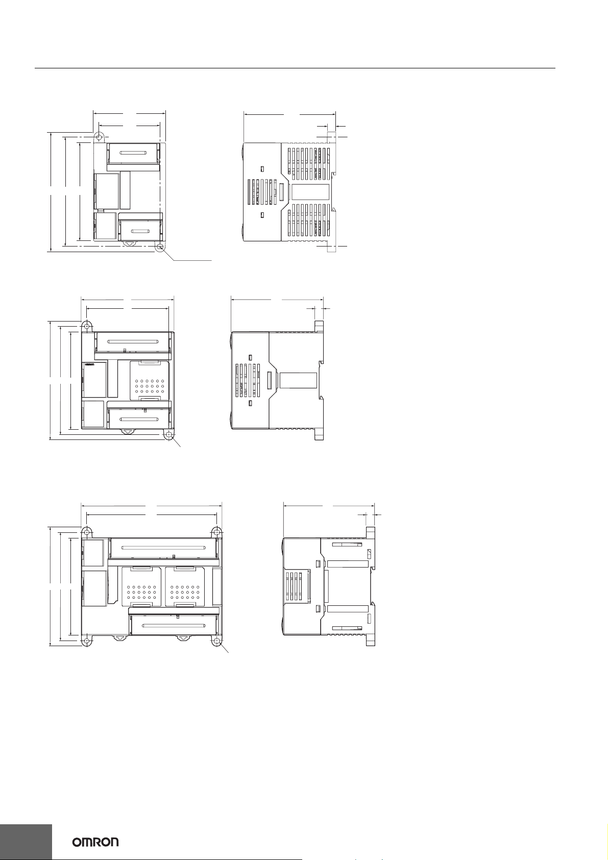
CP1E-E@@D@-@ CP1E-N@@D@-@/NA20D@-@
Dimensions (Unit: mm)
CP1E CPU Unit
●CPU Units with 10 I/O Points
66
56
110 100 90
Two, 4.5 dia.
●CPU Units with 14 or 20 I/O Points
86
76
90100
110
85
8
85
8
Two, 4.5 dia.
●CPU Units with 30 I/O Points
CPU Units with 20 I/O Points and Built-in Analog
130
120
90100
110
Four, 4.5 dia.
85
8
38
Page 39
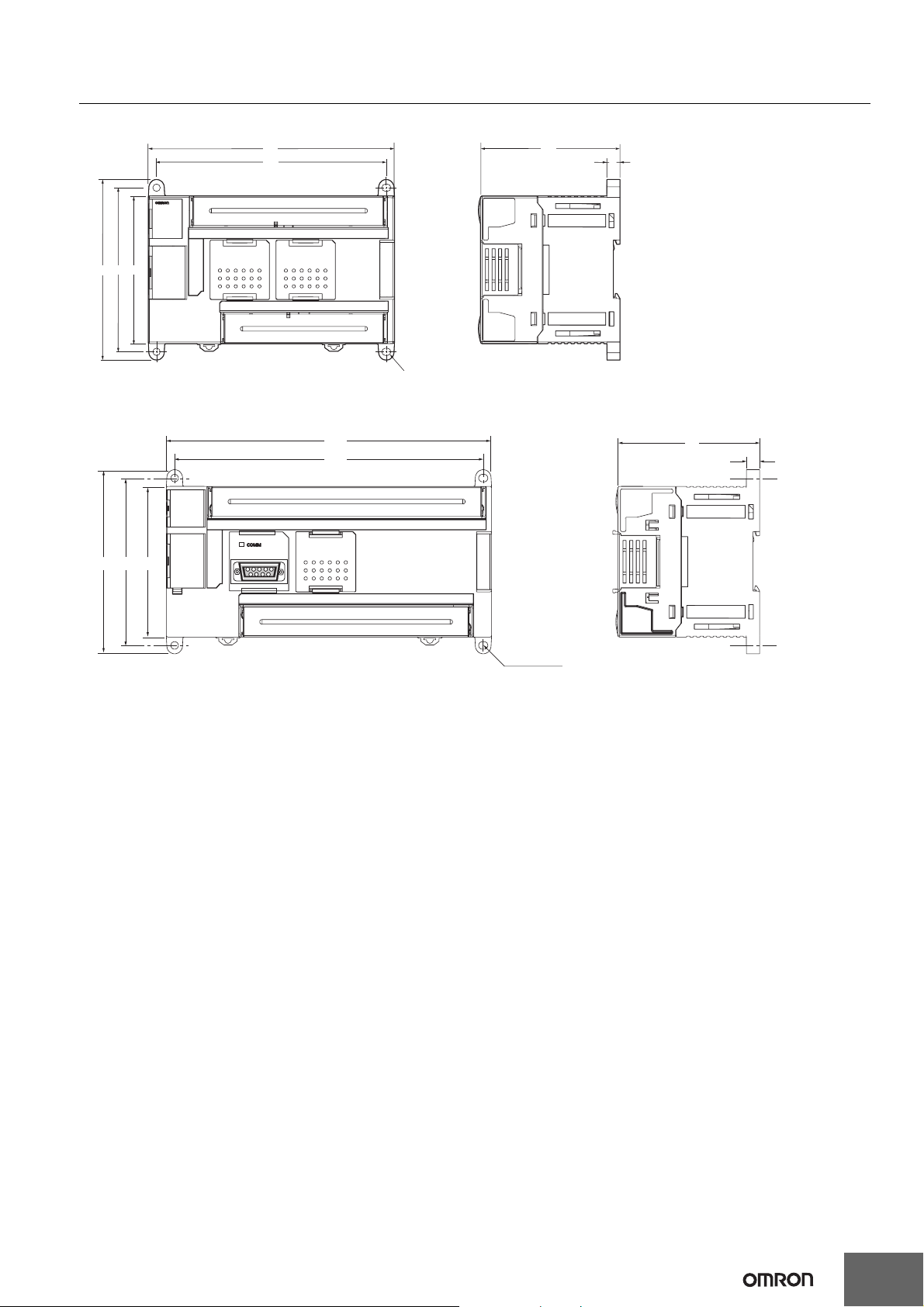
●CPU Units with 40 I/O Points
150
140
90100
110
●CPU Units with 60 I/O Points
195
185
CP1E-E@@D@-@ CP1E-N@@D@-@/NA20D@-@
85
8
Four, 4.5 dia.
85
8
110 100 90
Four, 4.5 dia.
39
Page 40
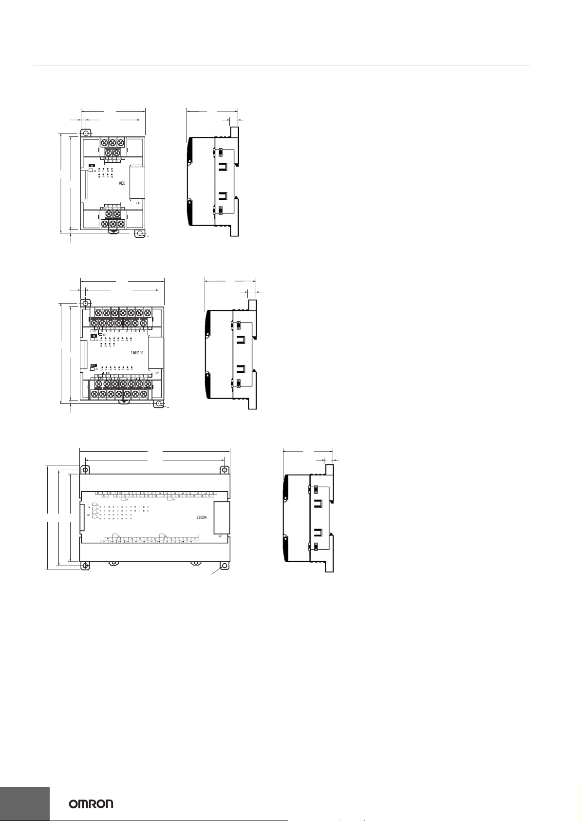
CP1E-E@@D@-@ CP1E-N@@D@-@/NA20D@-@
Expansion I/O Units and Expansion Units
●CP1W-8E@@/CP1W-SRT21
50
8
100±0.2
5
90
5
66
56±0.2
Two, 4.5 dia.
●CP1W-20ED@/CP1W-16E@@/CP1W-AD041/CP1W-DA041/CP1W-MAD11/CP1W-TS@@@
50
8
100±0.2
5
90
86
76±0.2
5
Two, 4.5 dia.
●CP1W-40ED@/CP1W-32E@@
150
140
90100110
50
8
Four, 4.5 dia.
40
Page 41

CP1E-E@@D@-@ CP1E-N@@D@-@/NA20D@-@
Related Manuals
Manual name Cat. No. Model numbers Application Contents
Describes the following information for
CP1E PLCs.
• Overview and features
• Basic system configuration
• Part names and functions
• Installation and settings
• Troubleshooting
Describes the following information for
CP1E PLCs.
• CPU Unit operation
• Internal memory
• Programming
• Settings
• CPU Unit built-in functions
• Interrupts
• High-speed counter inputs
• Pulse outputs
• Serial communications
• Analog I/O function
• Other functions
Describes each programming instruction in
detail.
When programming, use this manual
together with the CP1E CPU Unit
Hardware Manual (Cat. No. W479) and
CP1E CPU Unit Software Manual (Cat. No.
W480).
Describes 1) C-mode commands and 2)
FINS commands in detail.
Read this manual for details on C-mode
and FINS commands addressed to CPU
Units.
Describes the following information for
CP1L/CP1E PLCs.
• Basic configuration and component
names
• Mounting and wiring
• Programming, data transfer, and
debugging using the CX-Programmer
• Application program examples
SYSMAC CP Series CP1E
CPU Unit Hardware Manual
SYSMAC CP Series CP1E
CPU Unit Software Manual
SYSMAC CP Series CP1E
CPU Unit Instructions
Reference Manual
CS/CJ/CP/NSJ Series
Communications Commands
Reference Manual
SYSMAC CP Series
CP1L/CP1E CPU Unit
Introduction Manual
W479
W480
W483
W342
W461
CP1E-E@@D@-@
CP1E-N@@D@-@
CP1E-NA@@D@-@
CP1E-E@@D@-@
CP1E-N@@D@-@
CP1E-NA@@D@-@
CP1E-E@@D@-@
CP1E-N@@D@-@
-NA@@D@-@
CP1E
CS1G/H-CPU@@H
CS1G/H-CPU@@-V1
CS1D-CPU@@H
CS1D-CPU@@S
CS1W-SCU@@-V1
CS1W-SCB@@-V1
CJ1G/H-CPU@@H
CJ1G-CPU@@P
CJ1M-CPU@@
CJ1G-CPU@@
CJ1W-SCU@@-V1
CP1L-L10D@-@
CP1L-L14D@-@
CP1L-L20D@-@
CP1L-M30D@-@
CP1L-M40D@-@
CP1L-M60D@-@
CP1E-E@@D@-@
CP1E-N@@D@-@
CP1E-NA@@D@-@
To learn the hardware specifications of the
CP1E PLCs
Use this manual together with the CP1E CPU Unit Software Manual (Cat. No. W480) and
CP1E CPU Unit Instructions Reference Manual (Cat. No. W483).
To learn the software specifications of the
CP1E
Use this manual together with the CP1E CPU Unit Hardware Manual (Cat. No. W479)
and CP1E CPU Unit Instructions Reference Manual (Cat. No. W483).
To learn programming instructions in detail
To learn communications commands for
CS/CJ/CP/NSJ-series Controllers in detail
Note: This manual describes commands addressed to CPU Units. It does not cover
commands addressed to other Units or ports (e.g., serial communications ports
on CPU Units, communications ports on Serial Communications Units/Boards,
and other Communications Units).
rn the basic setup methods of the
To lea
CP1L/CP1E PLCs
41
Page 42

MEMO
42
Page 43

Read and Understand this Catalog
Please read and understand this catalog before purchasing the product. Please consult your OMRON representative if you have
any questions or comments.
Warranty and Limitations of Liability
WARRANTY
OMRON's exclusive warranty is that the products are free from defects in materials and workmanship for a period of one year
(or other period if specified) from date of sale by OMRON.
OMRON MAKES NO WARRANTY OR REPRESENTATION, EXPRESS OR IMPLIED, REGARDING NON-INFRINGEMENT,
MERCHANTABILITY, OR FITNESS FOR PARTICULAR PURPOSE OF THE PRODUCTS. ANY BUYER OR USER
ACKNOWLEDGES THAT THE BUYER OR USER ALONE HAS DETERMINED THAT THE PRODUCTS WILL SUITABLY MEET
THE REQUIREMENTS OF THEIR INTENDED USE. OMRON DISCLAIMS ALL OTHER WARRANTIES, EXPRESS OR
IMPLIED.
LIMITATIONS OF LIABILITY
OMRON SHALL NOT BE RESPONSIBLE FOR SPECIAL, INDIRECT, OR CONSEQUENTIAL DAMAGES, LOSS OF PROFITS
OR COMMERCIAL LOSS IN ANY WAY CONNECTED WITH THE PRODUCTS, WHETHER SUCH CLAIM IS BASED ON
CONTRACT, WARRANTY, NEGLIGENCE, OR STRICT LIABILITY.
In no event shall the responsibility of OMRON for any act exceed the individual price of the product on which liability is asserted.
IN NO EVENT SHALL OMRON BE RESPONSIBLE FOR WARRANTY, REPAIR, OR OTHER CLAIMS REGARDING THE
PRODUCTS UNLESS OMRON'S ANALYSIS CONFIRMS THAT THE PRODUCTS WERE PROPERLY HANDLED, STORED,
INSTALLED, AND MAINTAINED AND NOT SUBJECT TO CONTAMINATION, ABUSE, MISUSE, OR INAPPROPRIATE
MODIFICATION OR REPAIR.
Application Considerations
SUITABILITY FOR USE
OMRON shall not be responsible for conformity with any standards, codes, or regulations that apply to the combination of the
product in the customer's application or use of the product.
Take all necessary steps to determine the suitability of the product for the systems, machines, and equipment with which it will
be used.
Know and observe all prohibitions of use applicable to this product.
NEVER USE THE PRODUCT FOR AN APPLICATION INVOLVING SERIOUS RISK TO LIFE OR PROPERTY WITHOUT
ENSURING THAT THE SYSTEM AS A WHOLE HAS BEEN DESIGNED TO ADDRESS THE RISKS, AND THAT THE OMRON
PRODUCT IS PROPERLY RATED AND INSTALLED FOR THE INTENDED USE WITHIN THE OVERALL EQUIPMENT OR
SYSTEM.
PROGRAMMABLE PRODUCTS
OMRON shall not be responsible for the user's programming of a programmable product, or any consequence thereof.
Disclaimers
CHANGE IN SPECIFICATIONS
Product specifications and accessories may be changed at any time based on improvements and other reasons. Consult with
your OMRON representative at any time to confirm actual specifications of purchased product.
DIMENSIONS AND WEIGHTS
Dimensions and weights are nominal and are not to be used for manufacturing purposes, even when tolerances are shown.
PERFORMANCE DATA
Performance data given in this catalog is provided as a guide for the user in determining suitability and does not constitute a
warranty. It may represent the result of OMRON's test conditions, and the users must correlate it to actual application
requirements. Actual performance is subject to the OMRON Warranty and Limitations of Liability.
Page 44

Note: Do not use this document to operate the Unit.
OMRON Corporation Industrial Automation Company
Tokyo, JAPAN
Contact: www.ia.omron.com
Regional Headquarters
OMRON EUROPE B.V.
Wegalaan 67-69-2132 JD Hoofddorp
The Netherlands
Tel: (31)2356-81-300/Fax: (31)2356-81-388
OMRON ASIA PACIFIC PTE. LTD.
No. 438A Alexandra Road # 05-05/08 (Lobby 2),
Alexandra Technopark,
Singapore 119967
Tel: (65) 6835-3011/Fax: (65) 6835-2711
OMRON ELECTRONICS LLC
One Commerce Drive Schaumburg,
IL 60173-5302 U.S.A.
Tel: (1) 847-843-7900/Fax: (1) 847-843-7787
OMRON (CHINA) CO., LTD.
Room 2211, Bank of China Tower,
200 Yin Cheng Zhong Road,
PuDong New Area, Shanghai, 200120, China
Tel: (86) 21-5037-2222/Fax: (86) 21-5037-2200
Authorized Distributor:
© OMRON Corporation 2009 All Rights Reserved.
In the interest of product improvement,
specifications are subject to change without notice.
Cat. No. P061-E1-03
1209 (0309)
 Loading...