


Cat. No. I563-E1-01
USER’S MANUAL
3G3AX-RBU
Regenerative Braking Unit


Introduction
Thank you for choosing the Regenerative Braking Unit 3G3AX-RBU. This User's Manual
(hereinafter called “this manual”) describes the installation/wiring of the 3G3AX-RBU model, as well
as troubleshooting and inspection methods.
zThis manual should be delivered to the actual end user of the product.
zAfter reading this manual, keep it handy for future reference.
zThis manual describes the specifications and functions of the product as well as the relations
between them. You should assume that anything not described in this manual is not possible with
the product.
zIntended readers
This manual is intended for:
Those with knowledge of electrical systems (qualified electrical engineers or the equivalent), and
also in charge of:
• Introducing the control equipment
• Designing the control system
• Installing and/or connecting the control equipment
• Field management
Introduction
1

Read and Understand This Manual
Read and Understand This Manual
Please read and understand this manual before using the product. Please consult your OMRON representative
if you have any questions or comments.
Warranty and Limitations of Liability
WARRANTY
OMRON's exclusive warranty is that the products are free from defects in materials and workmanship for a
period of one year (or other period if specified) from date of sale by OMRON.
OMRON MAKES NO WARRANTY OR REPRESENTATION, EXPRESS OR IMPLIED, REGARDING
NON-INFRINGEMENT, MERCHANTABILITY, OR FITNESS FOR PARTICULAR PURPOSE OF THE
PRODUCTS. ANY BUYER OR USER ACKNOWLEDGES THAT THE BUYER OR USER ALONE HAS
DETERMINED THAT THE PRODUCTS WILL SUITABLY MEET THE REQUIREMENTS OF THEIR
INTENDED USE. OMRON DISCLAIMS ALL OTHER WARRANTIES, EXPRESS OR IMPLIED.
LIMITATIONS OF LIABILITY
OMRON SHALL NOT BE RESPONSIBLE FOR SPECIAL, INDIRECT, OR CONSEQUENTIAL
DAMAGES, LOSS OF PROFITS OR COMMERCIAL LOSS IN ANY WAY CONNECTED WITH THE
PRODUCTS, WHETHER SUCH CLAIM IS BASED ON CONTRACT, WARRANTY, NEGLIGENCE, OR
STRICT LIABILITY.
In no event shall the responsibility of OMRON for any act exceed the individual price of the product on
which liability is asserted.
IN NO EVENT SHALL OMRON BE RESPONSIBLE FOR WARRANTY, REPAIR, OR OTHER CLAIMS
REGARDING THE PRODUCTS UNLESS OMRON'S ANALYSIS CONFIRMS THAT THE PRODUCTS
WERE PROPERLY HANDLED, STORED, INSTALLED, AND MAINTAINED AND NOT SUBJECT TO
CONTAMINATION, ABUSE, MISUSE, OR INAPPROPRIATE MODIFICATION OR REPAIR.
2

Read and Understand This Manual
Application Considerations
SUITABILITY FOR USE
OMRON shall not be responsible for conformity with any standards, codes, or regulations that apply to
the combination of products in the customer's application or use of the products.
At the customer's request, OMRON will provide applicable third party certification documents identifying
ratings and limitations of use that apply to the products. This information by itself is not sufficient for a
complete determination of the suitability of the products in combination with the end product, machine,
system, or other application or use.
The following are some examples of applications for which particular attention must be given. This is not
intended to be an exhaustive list of all possible uses of the products, nor is it intended to imply that the
uses listed may be suitable for the products:
• Outdoor use, uses involving potential chemical contamination or electrical interference, or conditions
or uses not described in this manual.
• Nuclear energy control systems, combustion systems, railroad systems, aviation systems, medical
equipment, amusement machines, vehicles, safety equipment, and installations subject to separate
industry or government regulations.
• Systems, machines, and equipment that could present a risk to life or property.
Please know and observe all prohibitions of use applicable to the products.
NEVER USE THE PRODUCTS FOR AN APPLICATION INVOLVING SERIOUS RISK TO LIFE OR
PROPERTY WITHOUT ENSURING THAT THE SYSTEM AS A WHOLE HAS BEEN DESIGNED TO
ADDRESS THE RISKS, AND THAT THE OMRON PRODUCTS ARE PROPERLY RATED AND
INSTALLED FOR THE INTENDED USE WITHIN THE OVERALL EQUIPMENT OR SYSTEM.
PROGRAMMABLE PRODUCTS
OMRON shall not be responsible for the user's programming of a programmable product, or any
consequence thereof.
3

Read and Understand This Manual
Disclaimers
CHANGE IN SPECIFICATIONS
Product specifications and accessories may be changed at any time based on improvements and other
reasons.
It is our practice to change model numbers when published ratings or features are changed, or when
significant construction changes are made. However, some specifications of the products may be
changed without any notice. When in doubt, special model numbers may be assigned to fix or establish
key specifications for your application on your request. Please consult with your OMRON representative
at any time to confirm actual specifications of purchased products.
DIMENSIONS AND WEIGHTS
Dimensions and weights are nominal and are not to be used for manufacturing purposes, even when
tolerances are shown.
PERFORMANCE DATA
Performance data given in this manual is provided as a guide for the user in determining suitability and
does not constitute a warranty. It may represent the result of OMRON's test conditions, and the users
must correlate it to actual application requirements. Actual performance is subject to the OMRON
Warranty and Limitations of Liability.
ERRORS AND OMISSIONS
The information in this manual has been carefully checked and is believed to be accurate; however, no
responsibility is assumed for clerical, typographical, or proofreading errors, or omissions.
4
Safety Precautions
Safety Precautions
Indications and Meanings of Safety Information
In this user’s manual, the following precautions and signal words are used to provide information to ensure the
safe use of the Regenerative Braking Unit 3G3AX-RBU.
The information provided here is vital to safety. Strictly observe the precautions provided.
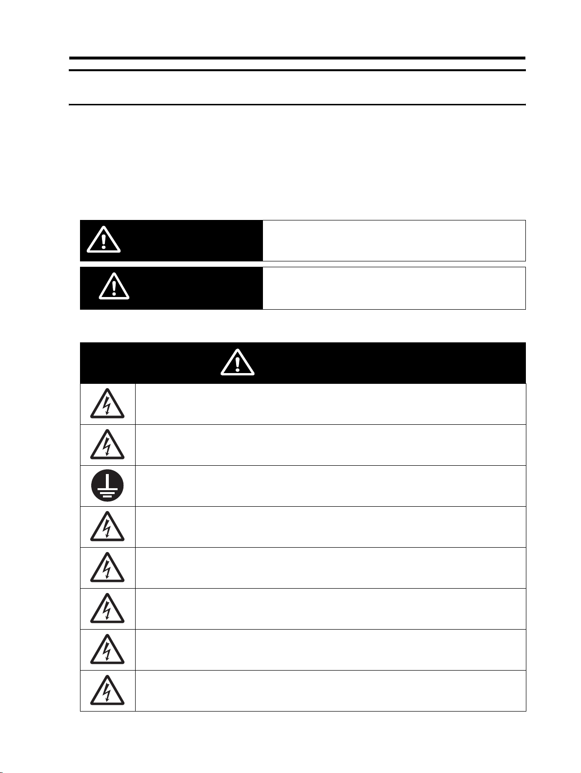
Meanings of Signal Words
Indicates an imminently hazardous situation which, if not
WARNING
CAUTION
avoided, is likely to result in serious injury or may result in death.
Additionally there may be severe property damage.
Indicates a potentially hazardous situation which, if not avoided,
may result in minor or moderate injury, or in property damage.
Alert Symbols in This Document
Turn off the power supply and implement wiring correctly.
Not doing so may result in a serious injury due to an electric shock.
Wiring work must be carried out only by qualified personnel.
Not doing so may result in a serious injury due to an electric shock.
Be sure to ground the unit.
Not doing so may result in a serious injury due to an electric shock or fire.
Do not remove the front cover during the power supply and 10 minutes after the power shutoff.
Doing so may result in a serious injury due to an electric shock.
Do not operate the switches with wet hands.
Doing so may result in a serious injury due to an electric shock.
Do not touch the inside of the Regenerative Braking Unit or terminals, and do not check a signal,
wire, put on or take off the connectors while the power is being supplied. Doing so may result in a
serious injury due to an electric shock or fire.
WARNING
Do not remove the front cover during the power supply. Doing so may result in a serious injury due
to an electric shock. Be sure to put on the front cover before turning on the input power.
Turn off the input power of the Inverter and wait for more than 10 minutes before changing wiring or
operating the DIP switch. Not doing so may result in a serious injury due to an electric shock.
5

Safety Precautions
Place covers on the openings or take other precautions to make sure that no metal objects such as
cutting bits or lead wire scraps go inside when installing and wiring.
Install a stop motion device to ensure safety. Not doing so might result in a minor injury.
Be sure to use a specified type of Braking Resistor/Regenerative Braking Unit. In case of a Braking
Resistor, install a thermal relay that monitors the temperature of the Resistor.
Not doing so might result in a moderate burn due to the heat generated in the Braking Resistor/
Regenerative Braking Unit.
Configure a sequence that enables the Inverter power to turn off when unusual overheating is
detected in the Braking Resistor/Regenerative Braking Unit.
Do not connect Resistors to the DC terminals (P, N) directly. Doing so might result in a small-scale
fire, heat generation or damage to the unit.
CAUTION
Do not touch the fins, Braking Resistors, which become too hot during the power supply and for
some time after the power shutoff. Doing so may result in a burn.
The models of 3G3AX-RBU23/-RBU24/-RBU42/-RBU43 do not have terminals for the alarm input
(R1, R2). Configure a sequence that enables the Inverter power to turn off when unusual overheating
is detected.
The 3G3AX-RBC Braking Resistor does not have a built-in thermal fuse. Be sure to use the alarm
contact terminals (AL1, AL2) of the Resistor and configure a sequence that enables the Inverter
power to turn off when unusual overheating is detected. Not doing so might result in a small-scale
fire, heat generation or damage to the unit.
Do not dismantle, repair or modify the product. Doing so may result in an injury.
6
Installation and Wiring
Turn off the power supply and implement wiring correctly.
Not doing so may result in a serious injury due to an electric shock.
Wiring work must be carried out only by qualified personnel.
Not doing so may result in a serious injury due to an electric shock.
Be sure to ground the unit.
Not doing so may result in a serious injury due to an electric shock or fire.
Safety Precautions
WARNING
CAUTION
Place covers on the openings or take other precautions to make sure that no metal objects such as
cutting bits or lead wire scraps go inside when installing and wiring.
Install a stop motion device to ensure safety. Not doing so might result in a minor injury.
Be sure to use a specified type of Braking Resistor/Regenerative Braking Unit. In case of a Braking
Resistor, install a thermal relay that monitors the temperature of the Resistor.
Not doing so might result in a moderate burn due to the heat generated in the Braking Resistor/
Regenerative Braking Unit.
Configure a sequence that enables the Inverter power to turn off when unusual overheating is
detected in the Braking Resistor/Regenerative Braking Unit.
Do not connect Resistors to the DC terminals (P, N) directly. Doing so might result in a small-scale
fire, heat generation or damage to the unit.
7
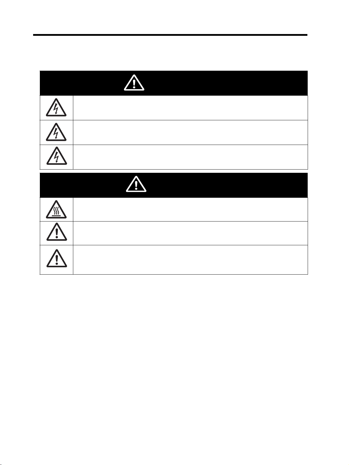
Safety Precautions
Operation
Do not remove the front cover during the power supply and 10 minutes after the power shutoff.
Doing so may result in a serious injury due to an electric shock.
Do not operate the switches with wet hands.
Doing so may result in a serious injury due to an electric shock.
Do not touch the inside of the Regenerative Braking Unit or terminals, and do not check a signal,
wire, put on or take off the connectors while the power is being supplied. Doing so may result in a
serious injury due to an electric shock or fire.
WARNING
CAUTION
Do not touch the fins, Braking Resistors, which become too hot during the power supply and for
some time after the power shutoff. Doing so may result in a burn.
The models of 3G3AX-RBU23/-RBU24/-RBU42/-RBU43 do not have terminals for the alarm input
(R1, R2). Configure a sequence that enables the Inverter power to turn off when unusual overheating
is detected.
The 3G3AX-RBC Braking Resistor does not have a built-in thermal fuse. Be sure to use the alarm
contact terminals (AL1, AL2) of the Resistor and configure a sequence that enables the Inverter
power to turn off when unusual overheating is detected. Not doing so might result in a small-scale
fire, heat generation or damage to the unit.
8
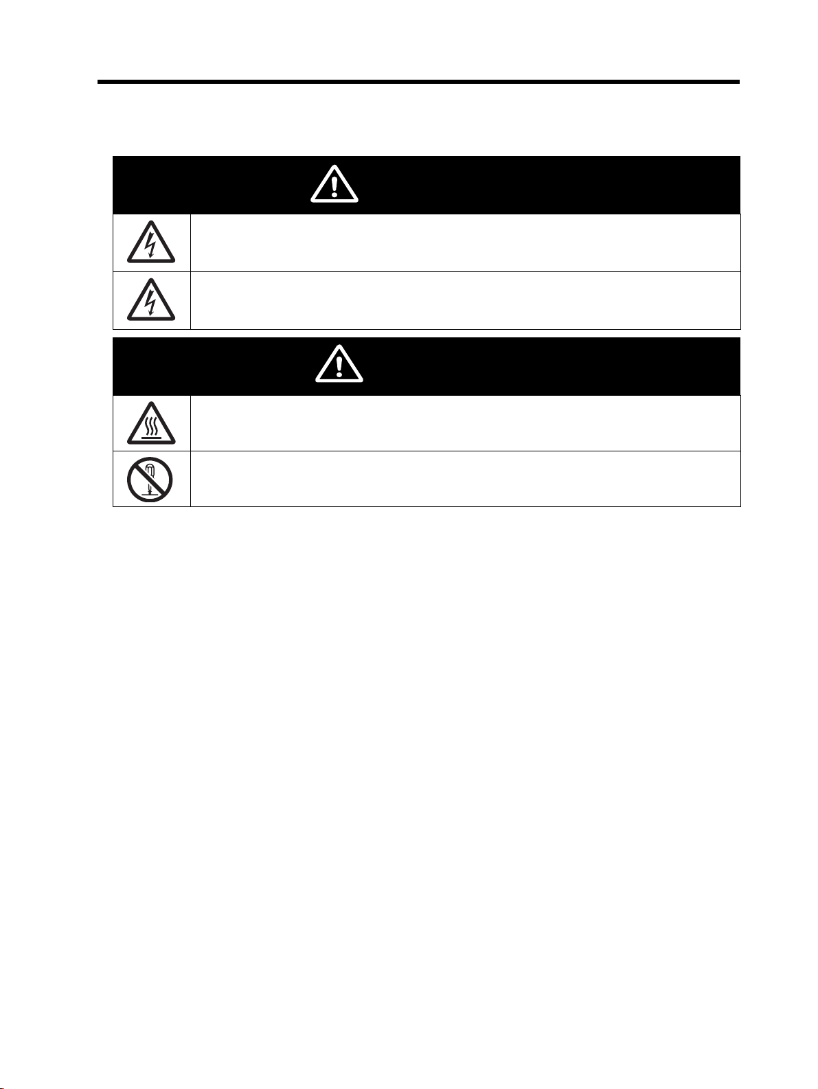
Maintenance and Inspection
Do not remove the front cover during the power supply. Doing so may result in a serious injury due
to an electric shock. Be sure to put on the front cover before turning on the input power.
Turn off the input power of the Inverter and wait for more than 10 minutes before changing wiring or
operating the DIP switch. Not doing so may result in a serious injury due to an electric shock.
Do not touch the fins, Braking Resistors, which become too hot during the power supply and for
some time after the power shutoff. Doing so may result in a burn.
Safety Precautions
WARNING
CAUTION
Do not dismantle, repair or modify the product. Doing so may result in an injury.
9

Precautions for Safe Use
Precautions for Safe Use
Installation and Storage
Do not store or use the product in the following places.
• Locations subject to direct sunlight.
• Locations subject to ambient temperature exceeding the specifications.
• Locations subject to relative humidity exceeding the specifications.
• Locations subject to condensation due to severe temperature fluctuations.
• Locations subject to corrosive or flammable gases.
• Locations subject to exposure to combustibles.
• Locations subject to dust (especially iron dust) or salt.
• Locations subject to exposure to water, oil, or chemicals.
• Locations subject to shock or vibration.
Transportation, Installation, and Wiring
Observe the following instructions during transportation, installation, and wiring.
• Do not drop or apply a strong impact on the product. Doing so may result in damaged parts or
malfunction.
• Do not hold by the front cover, but hold by the fins during transportation.
• The specified wire size or larger one must be used for the power lines.
Model
(3G3AX-)
RBU21 17 Ω min. 3.5 mm2 min.
RBU22 17 Ω min. 3.5mm
RBU23
RBU24
RBU41 34 Ω min. 3.5 mm
RBU42
RBU43
Connectable
resistance
8 Ω min. 5.5 mm
5 to 7.9 Ω 8 mm
4 to 4.9 Ω 14 mm
4 Ω min. 14 mm
3 to 3.9 Ω 22 mm
2 to 2.9 Ω 38 mm
17 Ω min. 3.5 mm
13 to 16.9 Ω 5.5 mm
10 to 12.9 Ω 8 mm
10 Ω min. 8 mm
7.5 to 9.9 Ω 14 mm
6 to 7.4 Ω 22 mm
P, RB, N
connection wires
2
min.
2
min.
2
min.
2
min.
2
min.
2
min.
2
min.
2
min.
2
min.
2
min.
2
min.
2
min.
2
min.
2
min.
SL1, SL2, MA1, MA2
connection wires
2
0.75 mm
min. 5.5 mm2 min.
Ground wire
10
Note 1. For wires connecting to the P, RB and N terminals use an MLFC wire (flame retardant
Polyflex wire, dielectric strength of 600 V).
Note 2. If the wiring length between the Regenerative Braking Unit and Braking Resistor exceeds
10 m, use the wire size larger than the specified one.

A wire of more than 10 m to 25 m : One rank higher wire size
A wire of more than 25 m to 50 m : Two ranks higher wire size
For the 3G3AX-RBU42 model, keep the wiring length between the Regenerative Braking
Unit and Braking Resistor within 5 m.
Maintenance and Inspection
Be sure to confirm safety before conducting maintenance, inspection or parts replacement.
Precautions for Safe Use
11
Precautions for Correct Use
Precautions for Correct Use
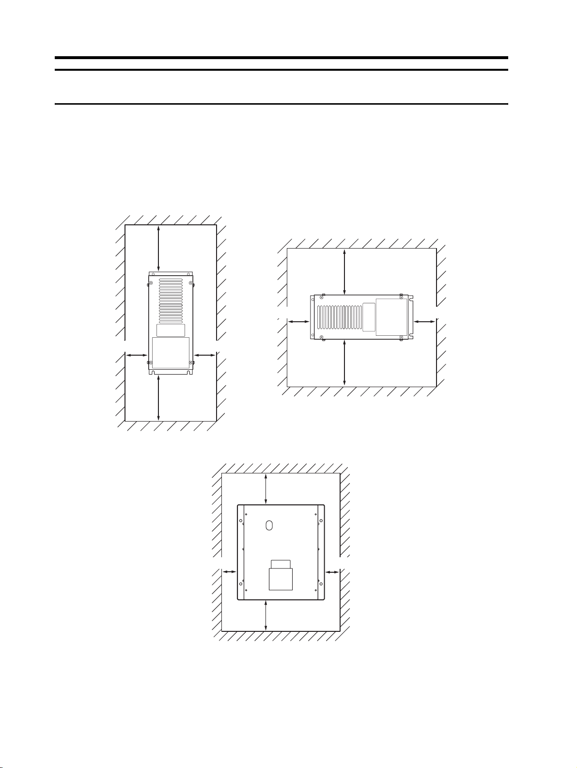
Installation
Mount the product on the vertical wall.
The material of the wall has to be nonflammable such as a metal plate, and do not place flammable
materials nearby.
3G3AX-RBU21/RBU22/RBU41/RBU42
10 cm min.
10 cm min.
5 cm min.5 cm min.
10 cm min.
3G3AX-RBU23/RBU24/RBU43
5 cm min.5 cm min.
10 cm min.
10 cm min.
5 cm min.5 cm min.
Note. The product cannot be mounted horizontally, but vertically only.
Rated Voltage
Confirm that the rated voltage of the product is the same as that of the Inverter to be used.
12
10 cm min.

Product Disposal
Comply with the local ordinance and regulations when disposing of the product.
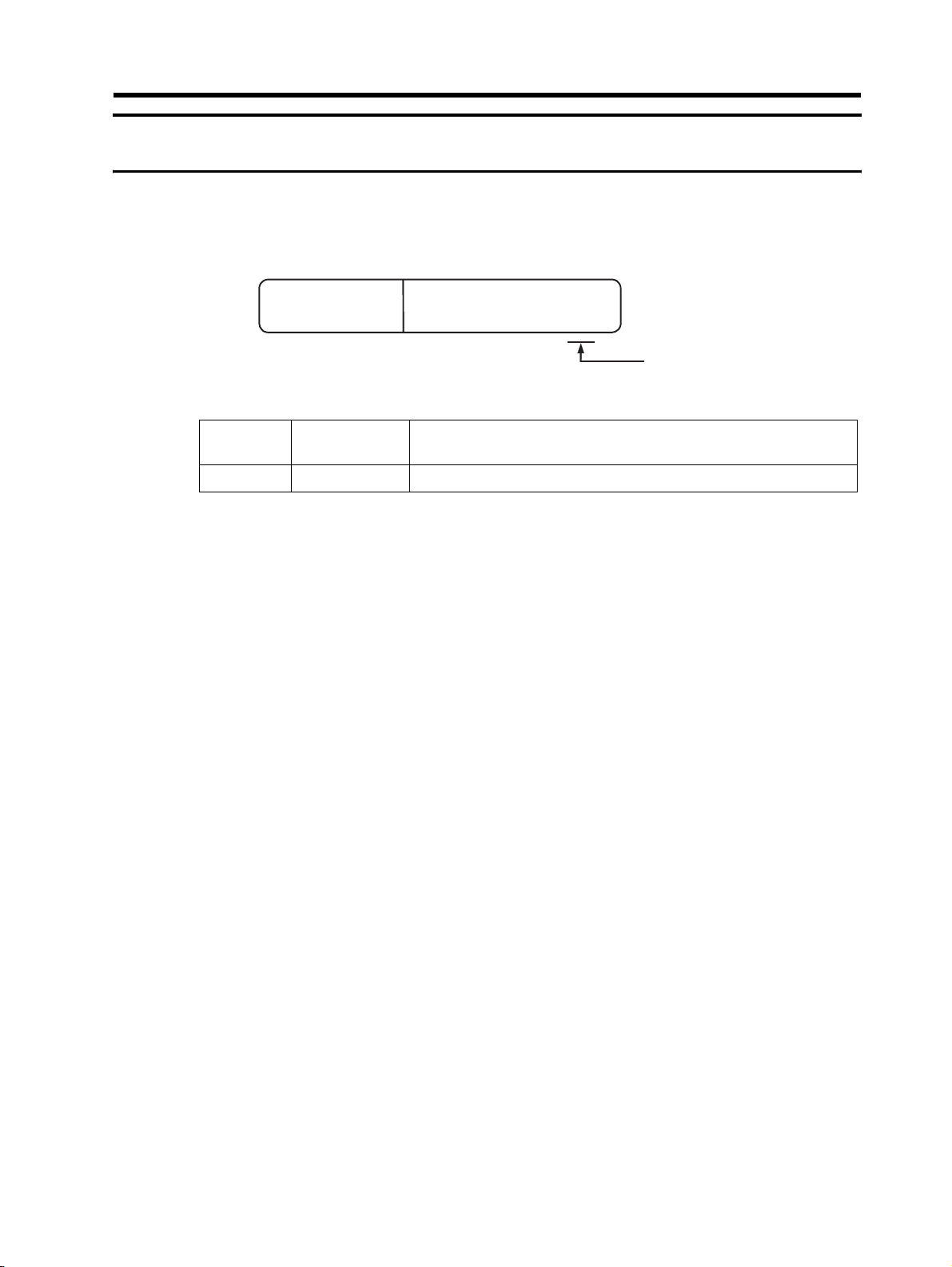
Warning Labels
Warning labels are located on the product as shown in the following illustration.
Be sure to follow the instructions.
Precautions for Correct Use
Warning Description
13
Checking Before Unpacking
Checking Before Unpacking
Checking the Product
On delivery, be sure to check that the delivered product is the Regenerative Braking Unit
3G3AX-RBU model that you ordered.
Should you find any problems with the product, immediately contact your nearest local sales
representative or OMRON sales office.
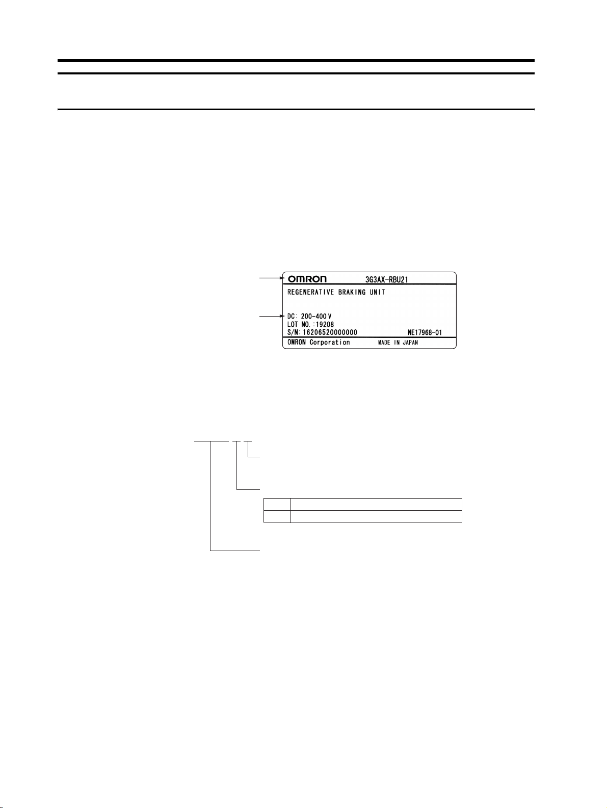
Checking the Nameplate
Regenerative Braking Unit
model name
Voltage specifications
Checking the Model
3G3AX− RBU21
Checking the Accessories
Note that this manual is the only accessory included with the Regenerative Braking Unit
3G3AX-RBU model.
Mounting screws and other necessary parts must be provided by the user.
Serial number
Maximum applicable motor capacity
24200-V class
400-V class
Regenerative Braking Unit
14
Revision History
e
A manual revision code appears as a suffix to the catalog number located at the lower left of the
front and back covers.
Revision History
Cat.No.
Revision
code
01 April 2008 First printing
Revision date Changes and revision pages
I563-E1-01
Revision cod
15

About This Manual
About This Manual
This User's Manual is compiled chapter by chapter for user's convenience as follows:
Understanding the following configuration ensures more effective use of the product.
Chapter Overview
Chapter 1 Design
Chapter 2 Functions Describes the DIP switch settings.
Chapter 3
Chapter 4
Chapter 5 Specifications Describes the product specifications and dimensions.
Maintenance
Operations
Inspection and
Maintenance
Describes installation and wiring procedures, terminal names and
other information required for design.
Describes the analysis of possible trouble causes as well as
troubleshooting methods.
Describes items for periodic inspection and/or maintenance for the
product.
16

Contents
Introduction.............................................................................................. 1
Read and Understand This Manual.........................................................2
Safety Precautions ..................................................................................5
Precautions for Safe Use......................................................................... 10
Precautions for Correct Use ....................................................................12
Checking Before Unpacking ....................................................................14
Revision History....................................................................................... 15
About This Manual...................................................................................16
Chapter 1 Design
1-1 Wiring....................................................................................................... 1-1
1-2 Terminals ................................................................................................. 1-3
1-3 Removing the Built-in Resistor ................................................................1-6
1-4 Connection............................................................................................... 1-7
Chapter 2 Functions
2-1 DIP Switch Setting ................................................................................... 2-1
Chapter 3 Maintenance Operations
3-1 Precautions before Operation.................................................................. 3-1
3-2 When the Alarm Contact is Activated ...................................................... 3-2
3-3 When an Inverter Overvoltage Trip Occurs ............................................. 3-3
Chapter 4 Inspection and Maintenance
4-1 Inspection and Maintenance.................................................................... 4-1
4-2 Daily Inspection and Periodic Inspection .................................................4-2
4-3 Megger Test.............................................................................................4-4
4-4 Checking the Main Element..................................................................... 4-5
4-5 Capacitor Life Curve ................................................................................ 4-6
Chapter 5 Specifications
5-1 Standard Specification List ...................................................................... 5-1
5-2 Dimensional Drawing...............................................................................5-5
17

Contents
18

Chapter 1
Design
1-1 Wiring................................................................ 1-1
1-2 Terminals .......................................................... 1-3
1-3 Removing the Built-in Resistor....................... 1-6
1-4 Connection ....................................................... 1-7

1-1 Wiring
1Design
1
Design
1-1 Wiring
For connections of the Regenerative Braking Unit, Inverter and Braking Resistor (P, RB, and N terminals), use cables with the following length:
Model
(3G3AX-)
RBU21 5 m max. 5 m max.
RBU22 5 m max. 5 m max.
RBU23 4 m max. 50 m max.
RBU24
RBU41 5 m max. 5 m max.
RBU42 4 m max. 5 m max.
RBU43 4 m max. 50 m max.
The wiring must be routed at the shortest distance. Be sure not to coil up any surplus cables. Doing
so may cause a fault in the equipment.
The cable connected to the P and N terminals for wiring between the Regenerative Braking Unit
and the Inverter, as well as the cable connected to the P and RB terminals for wiring between the
Regenerative Braking Unit and the Braking Resistor must be bundled with a tie band, so that these
cables are not placed at a distance.
Between Regenerative Braking Unit and
Inverter
Braking resistance: 4 Ω min. 4 m max.
Less than 4 Ω 3 m max.
Between Regenerative Braking Unit and
Braking Resistor
50 m max.
Correct example :
Incorrect example :
In order to prevent the Braking Register in the Regenerative Braking Unit from burning due to overheating, be sure to connect the alarm contacts (AL1 and AL2) and provide a circuit to turn off the
primary power supply for the Inverter.
When several Regenerative Braking Units are connected in parallel, the length of the signal cables
(MA1, MA2, SL1, SL2) between individual Regenerative Braking Units must be 5 m or less, and the
cable size must be 0.75 mm
cable.
Inverter
Inverter
Main circuit
cable
Regenerative
Braking Unit
Regenerative
Braking Unit
2
or more. Be sure to separate the signal cables from the main circuit
Signal cable
10 cm min.
Braking
Resistor
Braking
Resistor
1-1

1-1 Wiring
When multiple resistors are used in combination, a voltage rise during switching is increased due
to the internal inductive components of the resistor. In this case, increase the cable size, or twist the
cable.
For the Braking Resistor, use a non-inductive resistor. Do not use six or more resistors in combination.
For connections on the PCB terminal block, be sure to use crimp terminals with insulation coating.
To use the optional Braking Resistor, select the model with combined resistance higher than the
specified connectable resistance. If a resistor whose resistance is less than the connectable resistance is used, it may result in a fault of the Regenerative Braking Unit. Use thorough caution in regards to the resistance.
When using these Braking Resistors, be sure to remove the built-in resistor. (3G3AX-RBU21/RBU22/-RBU41 only)
Model
(3G3AX-)
RBU21 17 Ω min.
RBU22 17 Ω min.
RBU23 4 Ω min.
RBU24 2 Ω min.
RBU41 34 Ω min.
RBU42 10 Ω min.
Connectable resistance
1
Design
RBU43 6 Ω min.
1-2

1-2 Terminals
1
Design
1-2 Terminals
Terminal Position and Arrangement
The terminal arrangement on the Regenerative Braking Unit is shown below.
3G3AX-RBU21/-RBU22/-RBU41
Main circuit terminals (screw size:M4)
Tightening torque: 1.2 to 1.3 N⋅m
NRB P P
Control circuit terminals (screw size:M3)
Tightening torque: 0.6 to 0.9 N⋅m
SL1 SL2
Alarm terminals (screw size:M3)
Tightening torque: 0.5 to 0.6 N⋅m
AL1 AL2 R1 R2
MA1 MA2
3G3AX-RBU42
1-3
Main circuit terminals (screw size:M5)
Tightening torque: 3.4 to 3.7 N⋅m
NRB
Control circuit terminals (screw size:M3)
Tightening torque: 0.6 to 0.9 N⋅m
SL1 SL2 MA1
PP
MA2 AL1 AL2

1-2 Terminals
3G3AX-RBU23/-RBU43
3G3AX-RBU24
Main circuit terminals (screw size:M8)
Tightening torque: 12 to 13.5 N⋅m
NRB
Control circuit terminals (screw size:M3)
Tightening torque: 0.6 to 0.9 N⋅m
SL1 SL2 MA1 MA2
Alarm terminals (screw size:M3)
Tightening torque: 0.6 to 0.9 N⋅m
AL2 AL1
Main circuit terminals (screw size:M10)
Tightening torque: 25 to 28 N⋅m
NRB
PP
PP
1
Design
Control circuit terminals (screw size:M3)
Tightening torque: 0.6 to 0.9 N⋅m
SL1 SL2 MA1 MA2
Alarm terminals (screw size:M3)
Tightening torque: 0.5 to 0.6 N⋅m
AL2 AL1
1-4

1-2 Terminals
1
Terminal Description
Design
Terminal name
Main circuit
terminal
Control circuit
terminal
Alarm terminal
Terminal
symbol
N Connect to the N/− terminal of the Inverter.
Connect to the Braking Resistor.
RB
P Connect to the P/+2 terminal of the Inverter.
P
SL1
SL2
MA1
MA2
AL1
AL2
R1
R2
With the default connection, this terminal is connected to the builtin resistor.
(Only for the models 3G3AX-RBU21/-RBU22/-RBU41)
Connect to the Braking Resistor.
With the default connection, this terminal is connected to the builtin resistor.
(Only for the models 3G3AX-RBU21/-RBU22/-RBU41)
Connect to the MA1 and MA2 terminals of a master unit when
used as slave unit terminals in parallel operation.
Connect to the SL1 and SL2 terminals of a slave unit when used
as master unit terminals in parallel operation.
The alarm output terminals for the Regenerative Braking Unit.
Provide a circuit to turn off the primary power supply for the Inverter when the temperature relay of the built-in resistor or optional
Braking Resistor is activated.
Connect to the AL1, AL2 (1, 2) terminals of the Braking Resistor
when the optional Braking Resistor is used.
Short-circuit between the AL1 and AL2 terminals when the optional Braking Resistor is not used.
(Only for the models 3G3AX-RBU21/-RBU22/-RBU41)
Description
1-5

1-3 Removing the Built-in Resistor
1-3 Removing the Built-in Resistor
To remove the built-in resistor, follow the procedure described below (3G3AX-RB21/-RBU22/RBU41 only).
1. Disconnect the lead wires connected from the built-in resistor to the P and RB terminals on the PCB, and to the R1 and R2 terminals on the fin.
RB
P
PCB
AL1
AL2
R1
R2
Fin
1
Design
Disconnect all four cables.
Built-in resistor
2. Remove the built-in resistor from the bottom of the unit.
3. Reconnect the wiring between the AL1 and R1 terminals and between the AL2 and
R2 terminals on the fin.
1-6

1-4 Connection
1
Design
1-4 Connection
3G3AX-RBU21/-RBU22 Connection Example
When the built-in resistor is used
The following is an example of connections using the built-in resistor.
Up to five units can be connected in parallel.
For DIP switch settings, refer to "2-1 DIP Switch Setting"(page 2-1).
MC1
MC2
BSS
BS
EF
Inverter
R/L1
S/L2
T/L3
U/T1
V/T2
W/T3
P/+2
N/-
Motor
SL1SL2 AL1AL2
P
P
N
MA1MA2
3-phase
200 V
MC2
MCB
R
S
T
MC1
RY
3G3AX-RBU21
/-RBU22
Master
RB
R1
R2
RY
MC1
MC2
(*1)
1-7
Alarm terminal internal connections
SL1SL2 AL1 AL2
AL1 AL2
Built-in resistance
temperature relay
R1
R2
P
P
3G3AX-RBU21
N
/-RBU22
Slave
MA1MA2
SL1 SL2 AL1 AL2
P
P
3G3AX-RBU21
N
/-RBU22
Slave
MA1MA2
*1. To select RY, check the MC coil and RY contact specifications.
RB
R1
R2
RB
R1
R2

1-4 Connection
When the optional Braking Resistor 3G3AX-RBA/-RBB/-RBC is used
The following is an example of connections using the Braking Resistor 3G3AX-RBA/-RBB/-RBC.
Up to five units can be connected in parallel.
For parallel connection, use Braking Resistors with the same resistance. Be sure to remove the
built-in resistor from the bottom of the Regenerative Braking Unit.
For DIP switch settings, refer to "2-1 DIP Switch Setting"(page 2-1).
MC1
3-phase
200 V
MC2
BSS
BS
EF
MC2
MCB
R
S
T
MC1
R/L1
S/L2
T/L3
Inverter
U/T1
V/T2
W/T3
P/+2
N/-
Motor
SL1 SL2 AL1 AL2
P
P
3G3AX-RBU21
N
MA1MA2
RY
/-RBU22
Master
RB
R1
R2
RY
MC1
MC2
3G3AX-RBA
/-RBB/-RBC
1(AL1)
2(AL2)
1
Design
(*1)
RB
P
Alarm terminal internal connections
AL1 AL2
Built-in resistance
temperature relay
R1
R2
Temperature relay
*1. To select RY, check the MC coil and RY contact specifications.
•To use the Braking Resistor (3G3AX-RBA/-RBB/-RBC), be sure to remove the
built-in resistor. If the Braking Resistor (3G3AX-RBA/-RBB/-RBC) is used with the
built-in resistor connected, it may cause the built-in resistor to burn due to
overheating, or result in an overheating detection failure when the Braking Resistor
temperature relay is activated.
•To prevent overheating, be sure to connect the alarm contacts 1 (AL1) and 2 (AL2)
of the Braking Resistor.
3G3AX-RBA
/-RBB/-RBC
1 (AL1)
2 (AL2)
SL1 SL2 AL1 AL2
P
P
3G3AX-RBU21
N
/-RBU22
Slave
MA1MA2
SL1 SL2 AL1 AL2
P
P
3G3AX-RBU21
N
/-RBU22
Slave
MA1MA2
RB
R1
R2
RB
R1
R2
3G3AX-RBA
/-RBB/-RBC
1(AL1)
RB
2(AL2)
P
3G3AX-RBA
/-RBB/-RBC
1(AL1)
RB
2(AL2)
P
1-8

1-4 Connection
1
Design
3G3AX-RBU41 Connection example
When the built-in resistor is used
The following is an example of connections using the built-in resistor.
Up to five units can be connected in parallel.
For DIP switch settings, refer to "2-1 DIP Switch Setting"(page 2-1).
MC1
MC2
200 V 50/60 Hz
220 V 60 Hz
Operation power
supply
MCB
400 V
R
S
T
3-phase
MC1
MC2
BS
R/L1
S/L2
T/L3
Inverter
U/T1
V/T2
W/T3
P/+2
N/-
BSS
Motor
SL1 SL2 AL1 AL2
P
P
3G3AX-RBU41
N
MA1MA2
RY
Master
RB
R1
R2
RY
MC1
MC2
(*1)
Alarm terminal internal connections
AL1 AL2
Built-in resistance
temperature relay
R1
R2
SL1 SL2 AL1 AL2
P
P
3G3AX-RBU41
N
P
P
N
Slave
MA1MA2
SL1 SL2 AL1 AL2
3G3AX-RBU41
Slave
MA1MA2
*1. To select RY, check the MC coil and RY contact specifications.
RB
R1
R2
RB
R1
R2
1-9

1-4 Connection
When the optional Braking Resistor 3G3AX-RBA/-RBB/-RBC is used
The following is an example of connections using the Braking Resistor 3G3AX-RBA/-RBB/-RBC.
Up to five units can be connected in parallel.
For parallel connection, use Braking Resistors with the same resistance. Be sure to remove the
built-in resistor from the bottom of the Regenerative Braking Unit.
For DIP switch settings, refer to "2-1 DIP Switch Setting"(page 2-1).
RY
MC1
MC2
(*1)
1(AL1)
2(AL2)
1(AL1)
2(AL2)
200 V 50/60 Hz
220 V 60 Hz
Operation
power supply
MCB
R
3-phase
S
400 V
T
MC1
MC2
MC1
BS
R/L1
S/L2
T/L3
MC2
Inverter
U/T1
W/T3
P/+2
V/T2
N/-
BSS
Motor
SL1 SL2 AL1 AL2
P
P
3G3AX-RBU41
N
MA1MA2
RY
Master
RB
R1
R2
1
Design
RB
P
RB
P
Alarm terminal internal connections
AL1 AL2
Built-in resistance
temperature relay
R1
R2
Temperature relay
*1. To select RY, check the MC coil and RY contact specifications.
3G3AX-RBA
/-RBB/-RBC
1(AL1)
2(AL2)
SL1 SL2 AL1 AL2
P
P
3G3AX-RBU41
N
P
P
N
Slave
MA1MA2
SL1 SL2 AL1 AL2
3G3AX-RBU41
Slave
MA1MA2
3G3AX-RBA/-RBB/-RBC
Two resistors connected in series
1(AL1)
2(AL2)
1(AL1)
2(AL2)
1(AL1)
2(AL2)
1(AL1)
2(AL2)
RB
P
RB
P
RB
P
RB
P
RB
R1
R2
3G3AX-RBA/-RBB/-RBC
Two resistors connected in series
RB
R1
R2
3G3AX-RBA/-RBB/-RBC
Two resistors connected in series
1-10

1
Design
1-4 Connection
•To use the Braking Resistor (3G3AX-RBA/-RBB/-RBC), be sure to remove the
built-in resistor. If the Braking Resistor (3G3AX-RBA/-RBB/-RBC) is used with the
built-in resistor connected, it may cause the built-in resistor to burn due to
overheating, or result in an overheating detection failure when the Braking Resistor
temperature relay is activated.
•To use the Braking Resistor (3G3AX-RBA/-RBB/-RBC) for 3G3AX-RBU41, be sure
to connect two resistors of the same model in series. If the 3G3AX-RBU41 is
operated with a single resistor, the Braking Resistor may have a fault.
•To prevent overheating, be sure to connect the alarm contacts 1 (AL1) and 2 (AL2)
of the Braking Resistor.
1-11

1-4 Connection
3G3AX-RBU23/-RBU24 Connection Example
When the optional Braking Resistor 3G3AX-RBA/-RBB/-RBC is used
The following is an example of connections using the Braking Resistor 3G3AX-RBA/-RBB/-RBC.
Up to two units can be connected in parallel.
For parallel connection, use Braking Resistors with the same resistance.
For DIP switch settings, refer to "2-1 DIP Switch Setting"(page 2-1).
MC1
MC2
RY
/-RBU24
Master
RB
MC1
MC2
3G3AX-RBA
/-RBB/-RBC
1(AL1)
2(AL2)
3-phase
200 V
BSS
BS
EF
MC2
MCB
R
S
T
MC1
Inverter
R/L1
S/L2
T/L3
U/T1
V/T2
W/T3
P/+2
N/-
Motor
SL1 SL2 AL1 AL2
P
P
3G3AX-RBU23
N
MA1MA2
RY
1
Design
(*1)
RB
P
SL1 SL2 AL1 AL2
P
P
3G3AX-RBU23
N
/-RBU24
Slave
MA1MA2
*1. To select RY, check the MC coil and RY contact specifications.
•To prevent overheating, be sure to connect the alarm contacts 1 (AL1) and 2 (AL2)
of the Braking Resistor.
•The models of 3G3AX-RBU23/-RBU24 do not have terminals for the alarm input
(R1, R2). Configure a sequence that enables the Inverter power to turn off when
unusual overheating is detected.
RB
3G3AX-RBA
/-RBB/-RBC
1(AL1)
RB
2(AL2)
P
1-12

1-4 Connection
1
Design
3G3AX-RBU42/-RBU43 Connection Example
When the optional Braking Resistor 3G3AX-RBA/-RBB/-RBC is used
The following is an example of connections using the Braking Resistor 3G3AX-RBA/-RBB/-RBC.
Up to two units can be connected in parallel.
For parallel connection, use Braking Resistors with the same resistance.
For DIP switch settings, refer to "2-1 DIP Switch Setting"(page 2-1).
MC1
200 V 50/60 Hz
220 V 60 Hz
Operation
power supply
MCB
R
3-phase
S
400 V
T
MC1
MC2
BS
R/L1
S/L2
T/L3
MC2
Inverter
U/T1
V/T2
W/T3
P/+2
N/-
BSS
Motor
SL1 SL2 AL1 AL2
P
P
3G3AX-RBU42
N
MA1MA2
RY
RB
/-RBU43
Master
RY
MC1
MC2
3G3AX-RBA
/-RBB/-RBC
1(AL1)
2(AL2)
(*1)
RB
P
SL1 SL2 AL1 AL2
P
P
3G3AX-RBU42
N
/-RBU43
Slave
MA1MA2
RB
•A voltage of 800 V DC (max.) is applied to the Braking Resistor. Check the rated
dielectric strength of the resistor to be connected.
•To use the optional Braking Resistor (3G3AX-RBA/-RBB/-RBC), be sure to connect
two resistors of the same model in series. If the 3G3AX-RBU42 or -RBU43 is
operated with a single resistor, the Braking Resistor may have a fault.
•To prevent overheating, be sure to connect the alarm contacts 1 (AL1) and 2 (AL2)
of the Braking Resistor.
•The models of 3G3AX-RBU42/-RBU43 do not have terminals for the alarm input
(R1, R2). Configure a sequence that enables the Inverter power to turn off when
unusual overheating is detected.
*1. To select RY, check the MC coil and RY contact specifications.
3G3AX-RBA
/-RBB/-RBC
1(AL1)
RB
2(AL2)
P
1-13

Chapter 2
Functions
2-1 DIP Switch Setting ........................................... 2-1

2-1 DIP Switch Setting
2Functions
2-1 DIP Switch Setting
2
Operating voltage level setting (SW1, SW2)
Functions
Parallel operation settings (SW3, SW4)
Set up operating voltage level and parallel operation with the DIP switches.
Note: Be sure to turn off the power supply before setting the DIP switches.
The operating voltage of the Regenerative Braking Unit can be set at 3 levels: “Standard” (default
setting), “−5 %” and “−10 %”, by the DIP switch settings.
This function is useful in preventing an overvoltage trip by lowering the operating voltage of the Regenerative Braking Unit when an overvoltage trip occurs due to the receiving voltage, deceleration
time or other factor.
Depending on the receiving voltage, however, the Regenerative Braking Unit will operate continuously even by just turning on the Inverter power supply. When you change the DIP switch settings,
use thorough caution in regards to the receiving voltage.
Receiving voltage × √2 + 20 V < Operating voltage
Interlocking operation can be performed by two units (master and slave units) in parallel connection
via the signal lines (MA1, MA2, SL1, SL2) connection between the units and the DIP switch setting.
When a unit is set as the slave using the DIP switches, the operating voltage of the slave unit depends on the master unit settings.
The DIP switch settings are as follows:
Note: The DIP switches are located at the upper left of the PCB in the Regenerative Braking Unit.
The switch numbers are indicated on the switch body.
Setting functions
Master unit
Operating voltage level:
Standard
Master unit
Operating voltage level:
−5 %
Master unit
Operating voltage level:
−10 %
Slave unit
(X: Either ON or OFF is acceptable.)
DIP switch setting
OFF
OFF2ON3ON
1
ON
OFF2ON3ON
1
ON
1ON2ON3ON4
X
1X2
OFF3ON
Note
ON
OFF
4
ON
OFF
4
ON
OFF
ON
OFF
4
Default setting
Operating voltage of the
slave unit depends on the
master unit settings.
2-1

Chapter 3
Maintenance
Operations
3-1 Precautions before Operation......................... 3-1
3-2 When the Alarm Contact is Activated ............ 3-2
3-3 When an Inverter Overvoltage Trip Occurs... 3-3

3-1 Precautions before Operation
3Maintenance Operations
3-1 Precautions before Operation
Before operation, check the following items:
• There is no incorrect wiring.
Incorrect wiring may result in damage or malfunction of the Regenerative Braking Unit.
3
• Check for grounding of any terminal other than the ground terminal.
Improper grounding may result in damage or malfunction of the Regenerative Braking Unit.
• Check for any short-circuits caused by a wire scrap or crimp terminal left in the unit after wiring
work.
A short circuit may result in damage or malfunction of the Regenerative Braking Unit.
• There is no short circuit or ground fault.
A short circuit or ground fault may result in damage or malfunction of the Regenerative Braking
Unit.
Maintenance Operations
3-1

3-2 When the Alarm Contact is Activated
3-2 When the Alarm Contact is Activated
In principle, the alarm contacts of the Regenerative Braking Unit are activated when the Braking Resistor is overheated by excessive regenerative energy or frequent braking.
As a countermeasure, review the capacity of the Braking Resistor, model and number of Regenerative Braking Units, as well as Inverter deceleration time. Incorrect wiring and improper receiving
voltage can be also considered as a cause of an alarm. Use the flowchart to diagnose the problem:
Alarm contact is activated.
Is the main element (IGBT)
defective? (*1)
NO
Is the resistance higher than
"connectable resistance" selected?
YES
Regenerative Braking Unit is defective.
Replace or repair the unit.
NO
3
Maintenance Operations
YES
Are the units in parallel
operation?
NO
Is the operation LED indicator lit in
any other status than Inverter
deceleration (during Inverter
acceleration, or in standby status)?
NO
Is the main circuit terminals
correctly wired?
Review the resistor selection.
YES
During operation, are the
operation LED indicators of all
units lit?
YES
Does either the master or slave
unit have a wire breakage?
NO
YES
Is the Inverter's receiving voltage
outside ±10 % of the rated
voltage?
Is the control circuit terminals
correctly wired?
(For single operation, this terminal
need not be connected.)
YES
NO
YES
NO
Check the wiring and DIP switch
settings are correct.
YES
Replace the resistor.
Review resistor selection.
YES
Correct the voltage.
NO
Be sure to wire correctly and securely.
NO
Be sure to wire correctly and securely.
*1. For the IGBT check procedure, refer to "4-4 Checking the Main Element"(Page 4-5).
The Regenerative Braking Unit
is defective. Replace or repair
the unit.
3-2

3-3 When an Inverter Overvoltage Trip Occurs
3-3 When an Inverter Overvoltage Trip Occurs
In principle, an Inverter overvoltage trip occurs when the Inverter cannot completely absorb a voltage rise due to excessive regenerative energy.
As a countermeasure, review the resistance of the Braking Resistor, model and number of Regenerative Braking Units, as well as Inverter deceleration time. Wire breakage in the Breaking Resistor,
incorrect wiring, and/or improper DIP switch settings can be also considered as a cause of an In-
3
verter overvoltage trip. Use the flowchart to diagnose the problem:
Overvoltage trip occurs.
During Inverter deceleration,
is the operation LED indicator
lit?
NO
Maintenance Operations
Are the DIP switches set to
slave?
Set the DIP
switches to slave.
YES
The Braking Resistor model selection is improper. Review
resistor selection, or extend the inverter deceleration time.
(There may be a wire breakage in the Braking Resistor.)
NO
Is the operation LED indicator on
the master unit (or the unit in
single operation) unlit?
YES
Is wiring between the P and N
terminals, as well as the control
circuit terminals connection correct?
YES
The Regenerative Braking Unit
is defective. Replace or repair
the unit.
YES
Are the DIP switches set to
master?
YES
NO
Be sure to wire correctly and
securely.
Set the DIP
switches to master.
NONO
3-3

Chapter 4
Inspection and
Maintenance
4-1 Inspection and Maintenance........................... 4-1
4-2 Daily Inspection and Periodic Inspection...... 4-2
4-3 Megger Test ...................................................... 4-4
4-4 Checking the Main Element ............................ 4-5
4-5 Capacitor Life Curve ........................................ 4-6

4-1 Inspection and Maintenance
4Inspection and Maintenanc e
4-1 Inspection and Maintenance
Daily Inspection
Basically, check the following during operation.
1) There are no errors in the installation environment.
2) There are no errors in the cooling system.
3) There are no abnormal vibrations or sounds.
4
Cleaning
4) There are no abnormal overheat or discoloration.
5) There are no abnormal odors.
Always keep the Regenerative Braking Unit clean for operation.
Lightly remove any dirt with a soft cloth moistened with a neutral detergent.
Note: Do not use such solutions as acetone, benzene, toluene, or alcohol for cleaning. Doing so
may cause the Regenerative Braking Unit surface to dissolve or its coating to come off.
Periodic Inspection
Check the parts that cannot be checked without stopping operation, as well as those that require
periodic inspection.
1) Check that there are no errors in the cooling system (Clean the air filter).
2) Check that all parts that need tightening are secure (Screws and bolts may become loose because
of vibration or temperature change).
Inspection and Maintenance
3) Check that there is no corrosion or damage to the conductors and/or insulators.
4) Measurement of insulation resistance
5) Check and replace the capacitor.
4-1

4-2 Daily Inspection and Periodic Inspection
4-2 Daily Inspection and Periodic Inspection
Inspection
Daily
period
Inspection method Criteria Meter
1
year
Inspec-
tion part
Inspec-
tion item
Inspection point
General
Main
circuit
Ambient
environment
Entire
device
General
Check ambient
temperature, as
well as humidity
and dust levels.
Check that there
are no abnormal
vibrations or
sounds.
Megger test
(between main
circuit terminal
and ground
terminal)
Check that any
parts which may
need tightening
are secure.
Check that no
part has indications of overheating.
{
{
{
{
Refer to "Installation"(Page 12).
Visual or acoustic
inspection
Disconnect the wirings of the main
and the control circuit terminals, use
a megger to measure the resistance
{
between the
ground terminal
and the short-circuited parts of main
circuit terminals P,
RB, and N.
Tighten securely.
Visual inspection
Ambient temperature
−10 °C to 50 °C,
no freezing
Ambient humidity 90 %
max., no condensation.
No faults
5 M Ω min.
Refer to "4-3 Megger
Test".
No faults
Thermometer,
Hygrometer,
Recorder
500 V DC
megger
4
Inspection and Maintenance
Connection conductor and
wire
Terminal
block
Check that there
is no distortion
with the conductor.
Check that there
is no tearing in the
wire coverings.
Check that there
is no damage.
{
Visual inspection No faults
{
Visual inspection No faults
{
4-2

4-2 Daily Inspection and Periodic Inspection
Inspection
Daily
{
period
Inspection method Criteria Meter
1
year
Visual inspection.
Cement resistor,
wire-wound resistor, etc.
Disconnect one
end of the cable,
and measure the
{
resistance using a
tester.
Simulate the
protection circuit
{
output
No faults
Error must be within
±10% of the nominal
resistance.
Error is found in the sequence.
Tester,
Digital
multimeter
Inspec-
tion part
Main
circuit
4
Control
circuit
Protection
circuit
Inspec-
tion item
Resistor
Operation
check
Inspection point
There are no
crack or discoloration.
Check for any
wire breakage
Check that there
are no errors in
protection and
display circuits
through sequence
protection
operation.
Check that there
are no abnormal
General
Components
Inspection and Maintenance
Smoothing capacitor
on the
PCB
*1.
odors, discoloration, or significant
rusting.
Check that there
is no liquid leakage.
Check that the
safety valve has
not come out and
that there are no
bulges.
The life of the capacitor depends on ambient temperatures. Refer to "4-5 Capacitor Life Curve"(Page
4-6) for the replacement reference.
•Do not conduct a withstand voltage test on any part of the Regenerative Braking
Unit.
The Regenerative Braking Unit uses semiconductors in the main circuit. If the unit
undergoes a withstand voltage test, it may cause semiconductor deterioration.
{
{
Visual inspection No faults
{
Visual inspection
No faults
Standard replacement
period: 5 years (*1)
4-3

4-3 Megger Test
For a megger test of the external circuit, be sure to disconnect all the terminals of the Regenerative
Braking Unit, so as not to apply the test voltage to the Regenerative Braking Unit.
Use a high resistance tester for a power distribution test of the control circuit. Do not use a megger
or buzzer.
Conduct a Regenerative Braking Unit megger test only to the main circuit, not to the control circuit.
Use a 500 V DC megger for a megger test.
Gradually increase the applied voltage, and reduce it to 0 V.
To conduct a megger test for the main circuit, short-circuit the P, RB and N terminals with a wire.
Regenerative Braking Unit
4-3 Megger Test
4
P
RB
N
500 V DC megger
Ground terminal
Applied voltage Applied voltage
Time Time
0.1 s min. 0.1 s min.
Note: Do not connect the power cable.
Inspection and Maintenance
4-4

4-4 Checking the Main Element
4-4 Checking the Main Element
The quality of the main element can be checked using a tester.
Preparation
Make preparations for the check by following the procedure below.
1. Disconnect the cables (N, RB, P and P terminals), and the built-in resistor cable (RB
and P terminals).
4
Checking method
2. Prepare a tester. (Usable range is 1 Ω measurement resistance.)
The quality can be judged by measuring the conduction state of the N, RB and P terminals on the
Regenerative Braking Unit terminal block (main circuit terminals) while alternating the tester polarity.
Inspection and Maintenance
• First, measure the voltage between the P and N terminals in the DC voltage range. Then, make
sure that there is no residual voltage before performing the check.
• A nearly infinite value is shown in a no-conduction state. The value shown ranges from a few to a
few dozen Ω in a conduction state. If the measurement result for each item is as listed below, the
quality is judged as being acceptable.
IGBT
P
FD
(flywheel diode)
IGBT
(main element)
Tester polarity
+ (red) − (black)
RB N Conduction
N RB No conduction
RB
N
Measurement results
4-5
FD
P RB Conduction
RB P No conduction

4-5 Capacitor Life Curve
A
mbient
temperature
(°C)
50
12-hour operation/day
40
30
4-5 Capacitor Life Curve
4
20
10
0
-10
1
Note 1: Ambient temperature refers to the surrounding (atmospheric) temperature of the
Regenerative Braking Unit, or the temperature inside if it’s encased or installed in an
enclosure.
Note 2: The smoothing capacitor, which will waste because of the internal chemical reaction,
should normally be replaced once every 5 years.
If the ambient temperature is high, however, frequent operation of the Regenerative
Braking Unit will cause its service life to be significantly shortened due to capacitor
deterioration.
3
245678910
24-hour operation/day
Capacitor life (year)
Inspection and Maintenance
4-6

4-5 Capacitor Life Curve
4
Inspection and Maintenance
4-7

Chapter 5
Specifications
5-1 Standard Specification List............................. 5-1
5-2 Dimensional Drawing....................................... 5-5

5-1 Standard Specification List
5Specifications
5-1 Standard Specification List
Models with a Built-in Resistor (3G3AX-RBU21/-RBU22/-RBU41)
Voltage class 3-phase 200 V class 3-phase 400 V class
Model (3G3AX-) RBU21 RBU22 RBU41
Connectable resistance 17 Ω min. 17 Ω min. 34 Ω min.
Operating voltage
ON/OFF
(−5 % or −10 % setting available)
5
Operation indication LED ON (Lit)
Maximum number of
units in parallel
operation
*2
ON: 362.5 ± 5 V,
OFF: 355 ± 5 V
5 units
ON: 725 ± 5 V,
OFF: 710 ± 5 V
(−5 % or −10 %
setting available)
*1
Built-in resistance
Allowable consecutive ON time
Allowable operation cycle
Specifications
Built-in resistor
Power
consumption
Built-in resistance
overheat protection
Protective functions
Ambient
temperature
Ambient storage
temperature
Humidity 20 % to 90 % (with no condensation)
Vibration 5.9 m/s
Operating environment
Location At a maximum altitude of 1000m; indoors (without corrosive gases or dust)
120 W 180 Ω 120 W 20 Ω
10s max. 0.5s max. 10s max.
Cycle 1/10
(10s ON/90s OFF)
Instantaneous: 0.73 kW
Short-time rating: 120 W
Built-in relay specifications
• The temperature relay operates if the built-in resistor reaches approx. 200 °C or
more, and recovers at approx. 170 °C or less.
• Built-in thermal fuse (recovery impossible)
• Rating of contact 250 V AC 200 mA (R load)
12 V DC 500 mA(R load)
42 V DC 200 mA(R load)
• Minimum load 1 mA
−20 °C to 65 °C (short-time temperature during transport)
Cycle 1/80
(0.5s ON/40s OFF)
Instantaneous: 6.6 kW
Short-time rating: 120 W
*3
−10 °C to 50 °C
2
(0.6G) 10 to 55 Hz
120 W 180 Ω
x 2 in series
Cycle 1/10
(10s ON/90s OFF)
Instantaneous: 1.46 kW
Short-time rating: 240 W
Paint color Munsell 5Y7/1 (cooling fan: aluminum ground color)
*1. To use the Braking Resistor (3G3AX-RAB/-RBB/-RBC) for the 400-V class Regenerative
Braking Unit, be sure to remove the built-in resistor, and connect two resistors of the same
model in series.
If the 400-V class Regenerative Braking Unit is operated with a single Braking Resistor, the
Braking Resistor may be damaged.
*2. Set the DIP switches.
5-1

5-1 Standard Specification List
*3. The built-in resistor has a thermal fuse.
If the alarm terminal is not connected, the fuse may blow out in order to prevent the resistor
from burning due to overheating.
If the fuse blows out, the built-in resistor must be replaced.
5
Specifications
5-2

5-1 Standard Specification List
Models without a Built-in Resistor (3G3AX-RBU23/-RBU24/-RBU42/RBU43)
Voltage class 3-phase 200-V class 3-phase 400-V class
Model (3G3AX-) RBU23 RBU24 RBU42
Continuous
operation
6 Ω min. 4 Ω min. 24 Ω min. 12 Ω min.
*1
RBU43
*1
Short-time
operation/
Allowable operation
cycle / Allowable
continuous ON time
5
Specifications
Connectable resistance
Operating voltage
ON/OFF
Operation indication LED ON (Lit)
Maximum number of
units in parallel
operation
Built-in power
module overheat
protection
Protective functions
Ambient
temperature
Ambient storage
temperature
4 Ω min.
Cycle 1/5
(2 min ON/
8 min OFF)
2 min
ON: 362.5 ± 5 V, OFF: 355 ± 5 V
(−5 % or −10 % setting available)
*2
Built-in relay specifications
• The temperature relay operates if the cooling fin reaches approx. 100°C or more.
• Rating of contact 240 V AC 3 A (R load)
• Minimum load 5 V DC 50 mA (R load)
−20 °C to 65 °C (short-time temperature during transport)
2 Ω min.
Cycle 1/5
(2 min ON/
8 min OFF)
2 min
2 units
36 V DC 2 A(R load)
−10 °C to 50 °C
10 Ω min.
Cycle 1/10
(10 s ON/
90 s OFF)
10 s
ON: 725 ± 5 V, OFF: 710 ± 5 V
(−5 % or −10 % setting available)
6 Ω min.
Cycle 1/5
(2 min ON/
8 min OFF)
2 min
Humidity 20 % to 90 % (with no condensation)
2
Vibration 4.9 m/s
Location At a maximum altitude of 1000m; indoors (without corrosive gases or dust)
Operating environment
Paint color Munsell 5Y7/1 (cooling fan: aluminum ground color)
(0.5G) 10 to 55 Hz
*1. To use the Braking Resistor (3G3AX-RAB/-RBB/-RBC) for the 400-V class Regenerative
Braking Unit, be sure to connect two resistors of the same model in series.
If the 400-V class Regenerative Braking Unit is operated with a single Braking Resistor, the
Braking Resistor may be damaged.
*2. Set the DIP switches.
5-3

5-1 Standard Specification List
Specifications of Braking Resistors (3G3AX-RBA/-RBB/-RBC)
Model
Resistance (Ω) 180 100 50 35 180 100 50 35 50 35 17
Capacity (W) 120 200 300 400 400 600 1200
Allowable braking frequency
(%ED)
Allowable continuous braking
time(s)
1201 1202 1203 1204 2001 2002 3001 4001 4001 6001
5 2.5 1.5 1.0 10 7.5 7.5 7 10
20 12 5 3 30 20 10
3G3AX-RBA 3G3AX-RBB 3G3AX-RBC
12001
5
Specifications
5-4

5-2 Dimensional Drawing
5-2 Dimensional Drawing
3G3AX-RBU21/-RBU22/-RBU41
5
Specifications
3G3AX-RBU23
95
75
2-φ5
5
208
218
5
Ground terminal
Screw size : M5
145
35
100
217
237
258
258
4-φ8
16045
250
Ground terminal
Screw size : M5
151
86
51
109
5-5

3G3AX-RBU24
5-2 Dimensional Drawing
234
254
275
275
4-φ8
20050
300
Ground terminal
Screw size : M5
171
101
67
127
5
Specifications
3G3AX-RBU42
95
75
2-φ5
5208
218
5
Ground terminal
Screw size : M5
145
35
100
5-6

5-2 Dimensional Drawing
3G3AX-RBU43
217
237
258
5
258
4-φ8
250
16045
Ground terminal
Screw size : M5
151
86
51
109
Specifications
5-7


Terms and Conditions of Sale
1. Offer; Acceptance. These terms and conditions (these "Terms") are deemed
part of all quotes, agreements, purchase orders, acknowledgments, price lists,
catalogs, manuals, brochures and other documents, whether electronic or in
writing, relating to the sale of products or services (collectively, the "Products
by Omron Electronics LLC and its subsidiary companies (“Omron”). Omron
objects to any terms or conditions proposed in Buyer’s purchase order or other
documents which are inconsistent with, or in addition to, these Terms.
2. Prices; Payment Terms.
out notice by Omron. Omron reserves the right to increase or decrease prices
on any unshipped portions of outstanding orders. Payments for Products are
due net 30 days unless otherwise stated in the invoice.
3. Discounts.
sent to Buyer after deducting transportation charges, taxes and duties, and will
be allowed only if (i) the invoice is paid according to Omron’s payment terms
and (ii) Buyer has no past due amounts.
4. Interest.
the maximum legal rate, whichever is less, on any balance not paid within the
stated terms.
5. Orders
6. Governmental Approvals.
costs involved in, obtaining any government approvals required for the importation or sale of the Products.
7. Taxes
real property and income taxes), including any interest or penalties thereon,
imposed directly or indirectly on Omron or required to be collected directly or
indirectly by Omron for the manufacture, production, sale, delivery, importation, consumption or use of the Products sold hereunder (including customs
duties and sales, excise, use, turnover and license taxes) shall be charged to
and remitted by Buyer to Omron.
8. Financial.
to Omron, Omron reserves the right to stop shipments or require satisfactory
security or payment in advance. If Buyer fails to make payment or otherwise
comply with these Terms or any related agreement, Omron may (without liability and in addition to other remedies) cancel any unshipped portion of Products sold hereunder and stop any Products in transit until Buyer pays all
amounts, including amounts payable hereunder, whether or not then due,
which are owing to it by Buyer. Buyer shall in any event remain liable for all
unpaid accounts.
9. Cancellation; Etc.
unless Buyer indemnifies Omron against all related costs or expenses.
10. Force Majeure
resulting from causes beyond its control, including earthquakes, fires, floods,
strikes or other labor disputes, shortage of labor or materials, accidents to
machinery, acts of sabotage, riots, delay in or lack of transportation or the
requirements of any government authority.
11. Shipping; Delivery.
a. Shipments shall be by a carrier selected by Omron; Omron will not drop ship
b. Such carrier shall act as the agent of Buyer and delivery to such carrier shall
c. All sales and shipments of Products shall be FOB shipping point (unless oth-
d. Delivery and shipping dates are estimates only; and
e. Omron will package Products as it deems proper for protection against nor-
12. Claims.
Products occurring before delivery to the carrier must be presented in writing
to Omron within 30 days of receipt of shipment and include the original transportation bill signed by the carrier noting that the carrier received the Products
from Omron in the condition claimed.
13. Warranties
Products will be free from defects in materials and workmanship for a period of
twelve months from the date of sale by Omron (or such other period expressed
in writing by Omron). Omron disclaims all other warranties, express or implied.
(b) Limitations
EXPRESS OR IMPLIED, ABOUT NON-INFRINGEMENT, MERCHANTABIL-
Cash discounts, if any, will apply only on the net amount of invoices
Omron, at its option, may charge Buyer 1-1/2% interest per month or
. Omron will accept no order less than $200 net billing.
. All taxes, duties and other governmental charges (other than general
If the financial position of Buyer at any time becomes unsatisfactory
except in “break down” situations.
constitute delivery to Buyer;
erwise stated in writing by Omron), at which point title and risk of loss shall
pass from Omron to Buyer; provided that Omron shall retain a security interest in the Products until the full purchase price is paid;
mal handling and extra charges apply to special conditions.
Any claim by Buyer against Omron for shortage or damage to the
. (a) Exclusive Warranty. Omron’s exclusive warranty is that the
All prices stated are current, subject to change with-
Buyer shall be responsible for, and shall bear all
Orders are not subject to rescheduling or cancellation
. Omron shall not be liable for any delay or failure in delivery
Unless otherwise expressly agreed in writing by Omron:
. OMRON MAKES NO WARRANTY OR REPRESENTATION,
ITY OR FITNESS FOR A PARTICULAR PURPOSE OF THE PRODUCTS.
BUYER ACKNOWLEDGES THAT IT ALONE HAS DETERMINED THAT THE
PRODUCTS WILL SUITABLY MEET THE REQUIREMENTS OF THEIR
")
INTENDED USE. Omron further disclaims all warranties and responsibility of
any type for claims or expenses based on infringement by the Products or otherwise of any intellectual property right. (c) Buyer Remedy
gation hereunder shall be, at Omron’s election, to (i) replace (in the form
originally shipped with Buyer responsible for labor charges for removal or
replacement thereof) the non-complying Product, (ii) repair the non-complying
Product, or (iii) repay or credit Buyer an amount equal to the purchase price of
the non-complying Product; provided that in no event shall Omron be responsible for warranty, repair, indemnity or any other claims or expenses regarding
the Products unless Omron’s analysis confirms that the Products were properly handled, stored, installed and maintained and not subject to contamination, abuse, misuse or inappropriate modification. Return of any Products by
Buyer must be approved in writing by Omron before shipment. Omron Companies shall not be liable for the suitability or unsuitability or the results from the
use of Products in combination with any electrical or electronic components,
circuits, system assemblies or any other materials or substances or environments. Any advice, recommendations or information given orally or in writing,
are not to be construed as an amendment or addition to the above warranty.
See http://www.omron247.com
l
ished information.
14. Limitation on Liability; Etc
FOR SPECIAL, INDIRECT, INCIDENTAL, OR CONSEQUENTIAL DAMAGES,
LOSS OF PROFITS OR PRODUCTION OR COMMERCIAL LOSS IN ANY
WAY CONNECTED WITH THE PRODUCTS, WHETHER SUCH CLAIM IS
BASED IN CONTRACT, WARRANTY, NEGLIGENCE OR STRICT LIABILITY.
Further, in no event shall liability of Omron Companies exceed the individual
price of the Product on which liability is asserted.
15. Indemnities
their employees from and against all liabilities, losses, claims, costs and
expenses (including attorney's fees and expenses) related to any claim, investigation, litigation or proceeding (whether or not Omron is a party) which arises
or is alleged to arise from Buyer's acts or omissions under these Terms or in
any way with respect to the Products. Without limiting the foregoing, Buyer (at
its own expense) shall indemnify and hold harmless Omron and defend or settle any action brought against such Companies to the extent based on a claim
that any Product made to Buyer specifications infringed intellectual property
rights of another party.
16. Property; Confidentiality.
sive property of Omron Companies and Buyer shall not attempt to duplicate it
in any way without the written permission of Omron. Notwithstanding any
charges to Buyer for engineering or tooling, all engineering and tooling shall
remain the exclusive property of Omron. All information and materials supplied
by Omron to Buyer relating to the Products are confidential and proprietary,
and Buyer shall limit distribution thereof to its trusted employees and strictly
prevent disclosure to any third party.
17. Export Controls.
licenses regarding (i) export of products or information; (iii) sale of products to
“forbidden” or other proscribed persons; and (ii) disclosure to non-citizens of
regulated technology or information.
18. Miscellaneous
and no course of dealing between Buyer and Omron shall operate as a waiver
of rights by Omron. (b) Assignment
without Omron's written consent. (c) Law.
law of the jurisdiction of the home office of the Omron company from which
Buyer is purchasing the Products (without regard to conflict of law principles). (d) Amendment
Buyer and Omron relating to the Products, and no provision may be changed
or waived unless in writing signed by the parties. (e) Severability
sion hereof is rendered ineffective or invalid, such provision shall not invalidate
any other provision. (f) Setoff
against the amount owing in respect of this invoice. (g) Definitions
herein, “including
nies” (or similar words) mean Omron Corporation and any direct or indirect
subsidiary or affiliate thereof.
. Buyer shall indemnify and hold harmless Omron Companies and
Buyer shall comply with all applicable laws, regulations and
. (a) Waiver. No failure or delay by Omron in exercising any right
” means “including without limitation”; and “Omron Compa-
or contact your Omron representative for pub-
. OMRON COMPANIES SHALL NOT BE LIABLE
Any intellectual property in the Products is the exclu-
. Buyer may not assign its rights hereunder
These Terms are governed by the
. These Terms constitute the entire agreement between
. Buyer shall have no right to set off any amounts
. Omron’s sole obli-
. If any provi-
. As used
Certain Precautions on Specifications and Use
1. Suitability of Use. Omron Companies shall not be responsible for conformity
with any standards, codes or regulations which apply to the combination of the
Product in the Buyer’s application or use of the Product. At Buyer’s request,
Omron will provide applicable third party certification documents identifying
ratings and limitations of use which apply to the Product. This information by
itself is not sufficient for a complete determination of the suitability of the Product in combination with the end product, machine, system, or other application
or use. Buyer shall be solely responsible for determining appropriateness of
the particular Product with respect to Buyer’s application, product or system.
Buyer shall take application responsibility in all cases but the following is a
non-exhaustive list of applications for which particular attention must be given:
(i) Outdoor use, uses involving potential chemical contamination or electrical
interference, or conditions or uses not described in this document.
(ii) Use in consumer products or any use in significant quantities.
(iii) Energy control systems, combustion systems, railroad systems, aviation
systems, medical equipment, amusement machines, vehicles, safety equipment, and installations subject to separate industry or government regulations.
(iv) Systems, machines and equipment that could present a risk to life or property. Please know and observe all prohibitions of use applicable to this Product.
NEVER USE THE PRODUCT FOR AN APPLICATION INVOLVING SERIOUS
RISK TO LIFE OR PROPERTY OR IN LARGE QUANTITIES WITHOUT
ENSURING THAT THE SYSTEM AS A WHOLE HAS BEEN DESIGNED TO
ADDRESS THE RISKS, AND THAT THE OMRON’S PRODUCT IS PROPERLY RATED AND INSTALLED FOR THE INTENDED USE WITHIN THE
OVERALL EQUIPMENT OR SYSTEM.
2. Programmable Products.
user’s programming of a programmable Product, or any consequence thereof.
3. Performance Data
and other materials is provided as a guide for the user in determining suitability and does not constitute a warranty. It may represent the result of Omron’s
test conditions, and the user must correlate it to actual application requirements. Actual perfor mance is subject to the Omron’s Warranty and Limitations
of Liability.
4. Change in Specifications
changed at any time based on improvements and other reasons. It is our practice to change part numbers when published ratings or features are changed,
or when significant construction changes are made. However, some specifications of the Product may be changed without any notice. When in doubt, special part numbers may be assigned to fix or establish key specifications for
your application. Please consult with your Omron’s representative at any time
to confirm actual specifications of purchased Product.
5. Errors and Omissions.
checked and is believed to be accurate; however, no responsibility is assumed
for clerical, typographical or proofreading errors or omissions.
Omron Companies shall not be responsible for the
. Data presented in Omron Company websites, catalogs
. Product specifications and accessories may be
Information presented by Omron Companies has been

Note: Specifications are subject to change. © 2008 Omron Electronics LLC Printed in U.S.A.
OMRON ELECTRONICS LLC • THE AMERICAS HEADQUARTERS
Schaumburg, IL USA • 847.843.7900 • 800.556.6766 • www.omron247.com
OMRON CANADA, INC. • HEAD OFFICE
Toronto, ON, Canada • 416.286.6465 • 866.986.6766 • www.omron.ca
OMRON ELETRÔNICA DO BRASIL LTDA • HEAD OFFICE
São Paulo, SP, Brasil • 55.11.2101.6300 • www.omron.com.br
OMRON ELECTRONICS MEXICO SA DE CV • HEAD OFFICE
Apodaca, N.L. • 52.811.156.99.10 • mela@omron.com
OMRON ARGENTINA • SALES OFFICE
Cono Sur • 54.11.4787.1129
OMRON CHILE • SALES OFFICE
Santiago 56.2206.4592
OTHER OMRON LATIN AMERICA SALES
56.2206.4592
I563-E1-01
 Loading...