

Page 1
Inverter
RX Series
LX Series
MX2 Series
LCD Digital Operator
User’s Manual
I579-E2-01
3G3AX-OP05
Page 2

OMRON, 2013
All rights reserved. No part of this publication may be reproduced, stored in a retrieval system, or transmitted, in
any form, or by any means, mechanical, electronic, photocopying, recording, or otherwise, without the prior written
permission of OMRON.
No patent liability is assumed with respect to the use of the information contained herein. Moreover, because
OMRON is constantly striving to improve its high-quality products, the information contained in this manual is
subject to change without notice. Every precaution has been taken in the preparation of this manual. Nevertheless,
OMRON assumes no responsibility for errors or omissions. Neither is any liability assumed for damages resulting
from the use of the information contained in this publication.
Page 3

1
Introduction
LCD Digital Operator User’s Manual (I579)
Introduction
Thank you for purchasing the LCD Digital Operator (Model: 3G3AX-OP05).
This manual explains how to set parameters required to use the LCD Digital Operator (Model:
3G3AX-OP05), operation procedures and the remedies needed if problems occur.
For the use of the LCD Digital Operator 3G3AX-OP05, please refer also to RX (I560-E2), LX
(I120E-EN) or MX2 (I570-E2) User’s Manuals.
This manual is intended for the following individuals.
Those who have electrical knowledge (certified electricians or individuals who have equivalent
knowledge) and also are qualified for one of the following:
• Introducing control equipment
• Designing control systems
• Installing and connecting control systems
• Managing control systems and facilities
This manual contains information you need to know in order to correctly use the LCD Digital Operator
3G3AX-OP05.
Before using the LCD Digital Operator (Model: 3G3AX-OP05), read this manual and gain a full
understanding of the information provided herein.
After you finished reading this manual, keep it in a convenient place so that it can be referenced at any
time.
Make sure this manual is delivered to the end user.
Intended Readers
Notice
Page 4

Manual Configuration
2
LCD Digital Operator User’s Manual (I579)
Manual Configuration
This manual is compiled section by section for user’s convenience as follows.
Overview
Section 1 Overview This section provides features and specifications of the LCD Digital
Operator.
Section 2 Part Names and Functions This section describes the part names and functions of the LCD Digital
Operator.
Section 3 Installation and Wiring This section provides information on the installation and wiring of the
LCD Digital Operator.
Section 4 Operation Procedures This section provides an overview of the display modes supported by
LCD Digital Operator and how to operate the LCD Digital Operator in
each display mode.
Section 5 LCD Digital Operator Related
Parameters
This section describes the Inverter parameters related to the LCD Digital
Operator.
Section 6
Read/Write Functio ns This section describes how to read and write Inverter parameter settings
using the LCD Digital Operator.
Section 7 Error Messages and
Troubleshooting
This section describes the error messages and troubleshooting of the
LCD Digital Operator.
Section 8 Maintenance This section provides information on the maintenance of the LCD Digital
Operator.
Page 5
3
Manual Structure
LCD Digital Operator User’s Manual (I579)
Manual Structure
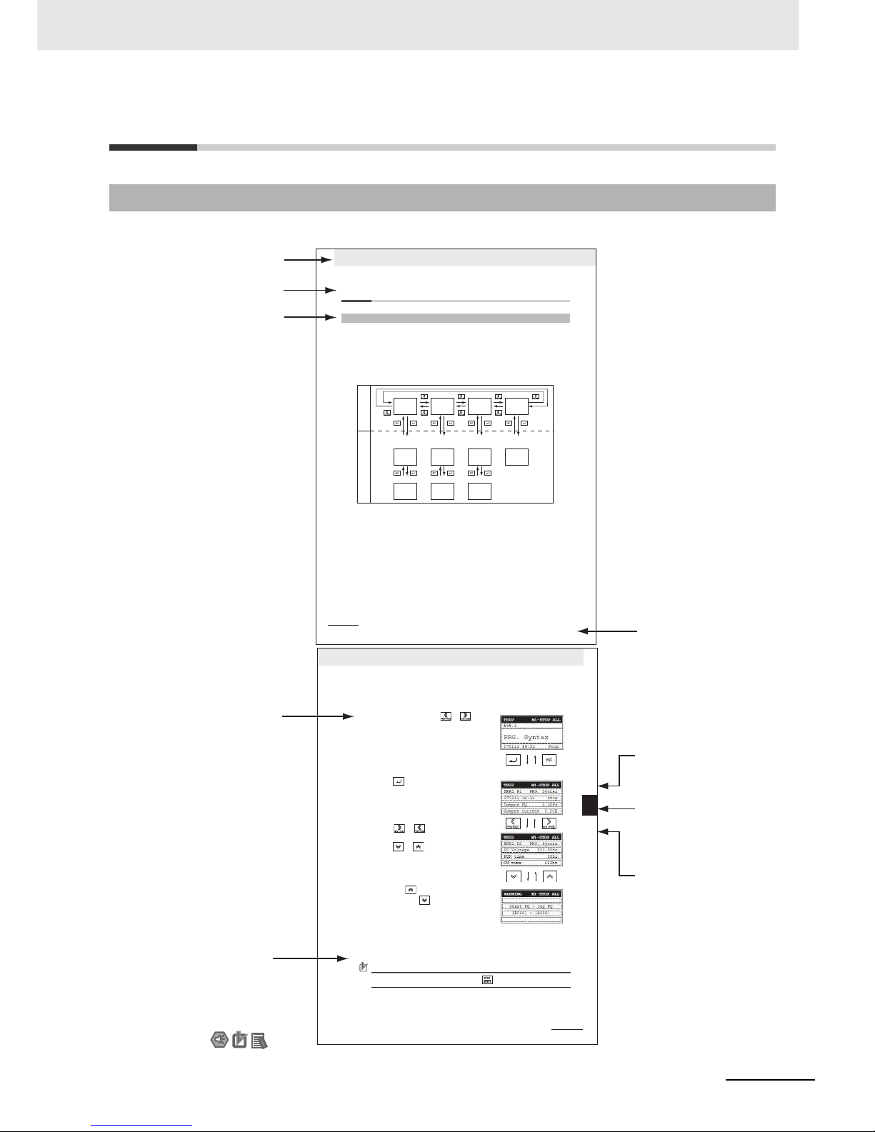
The following page structure and symbol icons are used in this manual.
Note The above page is only a sample for illustrative purposes. It is not the actual content of the manual.
Page Structure and Symbol Icons
4 Operation Procedures
4 - 2
LCD Digital Operator User’s Manual
4-1 Overview of Display Modes
The LCD Digital Operator basically displays its screens in four modes as shown below.
Each mode has two levels: the higher Navigation level and the lower Edit level. The user can move
between each mode in the Navigation level only.
•
Monitor Mode A: The mode to display and set a single monitor function and a single parameter function.
• Monitor Mode B: The mode to display up to four monitor functions on a single screen.
• Function
Mode
: The
mode
to set parameter settings. The screen also displays the parameter name
and setting range.
• Trip Mode: The mode to display the trip and warning information.
In addition to the above, the LCD Digital Operator has the following three called modes. At any of the
above levels and in any operating state, you can call these modes by pressing the key(s) shown to the
right of the down arrow above each screen, as shown below. After calling these screens, you can press
the ESC key to restore the operating state before the call.
• All Read: The mode to read all Inverter parameter settings and Drive Programming data from the
Inverter.
• All Write: The mode to write all the stored Inverter parameter setting and Drive Programming program
data to the Inverter.
• Option Mode: The mode to set the LCD Digital Operator.
4-1-1 Transition of Screens
Monitor
Mode A
Monitor
Mode B
Function
Mode
Trip
Mode
Select the monitor item.
Select the setting item.
Select the setting
line.
Select the setting
item.
Monitor the overall
trip history.
Monitor
Mode A
Monitor
Mode B
Function
Mode
Tri p
Mode
Monitor
Mode A
Monitor
Mode B
Function
Mode
Change the set value. Change the set value. Change the set value.
Navigation levelEdit level
Level 2 heading
Level 3 heading
Level 1 heading
Manual Name
Level 2 heading
Section Number of
Level 1 heading
Level 3 heading
Shows which section
the content of the current
page belongs to.
Shows which sub-section
the content of the current
page belongs to.
Shows which paragraph
the content of the current
page belongs to.
Note, Supplementary
Information, Reference Target
A note, supplementary
information, reference target,
etc. are provided with
difference icons.
Operation Steps
Describes
the operation steps.
4 Operation Procedures
4 - 8
LCD Digital Operator User’s Manual
1
At the Navigation level, press the or
key to select the Trip Mode screen.
2
Press the key. Now, the screen shows
information on the past trips (six trip errors)
recorded in the Inverter and the warning
information (for a single occurrence).
The trip information for a single occurrence comprises
two pages.
To switch from page 1 (P1) to page 2 (P2),
press the or key.
To display the information on the past six trip errors,
press the or key.
3
If you press the key when ERR1 is being
displayed or press the key when ERR6 is
being displayed, the screen changes to the
Warning Mode.
Precautions for Correct UsePrecautions for Correct Use
If a trip occurs, the ALARM LED lights up. Then, press the key to reset the Inverter.
4-5 Operation in the Trip Mode
4
4-1-2 Basic Operation
Page 6

Manual Structure
4
LCD Digital Operator User’s Manual (I579)
Special information in this manual is classified as follows:
Precautions for Safe Use
Precautions on what to do and what not to do to ensure safe usage of the product.
Precautions for Correct UsePrecautions for Correct Use
Precautions on what to do and what not to do to ensure proper operation and performance.
Additional Information
Additional information to read as required.
This information is provided to increase understanding or make operation easier.
Special Informati on
Page 7

5
Sections in this Manual
LCD Digital Operator User’s Manual (I579)
1
2
3
4
5
6
7
8
1
2
3
4
5
6
7
8
Overview
Part Names and Functions
Installation and Wiring
Operation Procedures
LCD Digital Operator Related Parameters
Read/Write Functions
Error Messages and Troubleshooting
Maintenance
I
I
Index
Sections in this Manual
Page 8

6
LCD Digital Operator User’s Manual (I579)
CONTENTS
CONTENTS
Introduction ...............................................................................................................1
Manual Configuration ...............................................................................................2
Manual Structure.......................................................................................................3
Sections in this Manual............................................................................................5
CONTENTS.................................................................................................................6
Read and Understand this Manual ..........................................................................8
Safety Precautions............................................ ..... ................................. ................11
Precautions for Safe Use........................................................................................13
Precautions for Correct Use...................................................................................15
Regulations and Standards...................................................... .... ..........................16
Items to Check after Unpacking.............................................................................17
Related Manuals............................................................................ ..........................18
Revision History......................................................................................................19
Section 1 Overview
1-1 Features.................................................................................................................................... 1-2
1-2 Supported Models ...................................................................................................................1-4
1-3 Specifications .......................................................................................................................... 1-5
1-4 External Dimensions ............................................................................................................... 1-6
1-5 Recommended Cables ............................................................................................................ 1-7
Section 2 Part Names and Function s
2-1 Part Names............................................................................................................................... 2-2
2-2 Operation Keys ........................................................................................................................2-4
2-3 LCD Display ...... ...... ....... ...... ....... ...... ....... ............................................. ...... ....... ...... .... ............ 2-6
Section 3 Installation and Wiring
3-1 Installation on the Inverter......................................................................................................3-2
3-1-1 Direct Installation on the Inverter................................................................................................3-3
3-1-2 Installation on the Inverter via Cable...........................................................................................3-4
3-1-3 Checking the Operation After Installation....................................................................................3-5
3-1-4 Date and Time Setting ................................................................................................................3-6
3-1-5 Other Settings.............................................................................................................................3-6
Page 9

7
LCD Digital Operator User’s Manual (I579)
CONTENTS
Section 4 Operation Procedures
4-1 Overview of Display Modes....................................................................................................4-2
4-1-1 Transition of Screens..................................................................................................................4-2
4-1-2 Overview of Each Mode..............................................................................................................4-3
4-1-3 Changing the Display in Each Mode........................................................................................... 4-5
4-2 Operation in the Monitor Mode A........................................................................................... 4-6
4-3 Operation in the Monitor Mode B........................................................................................... 4-7
4-4 Operation in the Function Mode ............................................................................................ 4-8
4-5 Operation in the Trip Mode..................................................................................................... 4-9
Section 5 LCD Digital Operator Related Parameter s
5-1 Parameter Setting.................................................................................................................... 5-2
5-1-1 Operation in the Option Mode..................................................................................................... 5-2
5-1-2 Details of Each Option Mode Parameter .................................................................................... 5-4
5-2 Related Inverter Parameters................................................................................................... 5-6
Section 6 Read/Write Functions
6-1 Single READ Function ............................................................................................................ 6-2
6-2 Single WRITE Function........................................................................................................... 6-3
6-3 Quad READ Function .............................................................................................................. 6-4
6-4 Quad VERIFY Function ........................................................................................................... 6-6
6-5 Quad WRITE Function............................................................................................................. 6-8
6-6 Conditions for the Read/Write Operations.......................................................................... 6-10
Section 7 Error Messages and Troubleshooting
7-1 Error Messages and Remedies .............................................................................................. 7-2
7-1-1 Inverter Error Messages.............................................................................................................7-2
7-1-2 LCD Digital Operator Error Messages........................................................................................7-2
7-2 Troubleshooting ...................................................................................................................... 7-5
Section 8 Maintenance
8-1 Battery Replacement............................................................................................................... 8-2
Index
Page 10

Read and Understand this Manual
8
LCD Digital Operator User’s Manual (I579)
Read and Understand this Manual
Warranty and Limitations of Liability
WARRANTY
OMRON’s exclus ive w arran ty is th at the prod uc t s a re free from defe cts in materials and workmanship for a period of
one year (or other period if specified) from date of sale by OMRON.
OMRON MAKES NO WARRANTY OR REPRESENTATION, EXPRESS OR IMPLIED, REGARDING
NONINFRINGEMENT, MERCHANTABILITY, OR FITNESS FOR PARTICULAR PURPOSE OF THE PRODUCTS.
ANY BUYER OR USER ACKNOWLEDGES THAT THE BUYER OR USER ALONE HAS DETERMINED THAT THE
PRODUCTS WILL SUIT ABLY MEET THE REQUIREMENTS OF THEIR INTENDED USE. OMRON DISCLAIMS ALL
OTHER WARRANTIES, EXPRESS OR IMPLIED.
LIMITATIONS OF LIABILITY
OMRON SHALL NOT BE RESPONSIBLE FOR SPECIAL, INDIRECT, OR CONSEQUENTIAL DAMAGES, LOSS
OF PROFITS OR COMMERCIAL LOSS IN ANY WAY CONNECTED WITH THE PRODUCTS, WHETHER SUCH
CLAIM IS BASED ON CONTRACT, WARRANTY, NEGLIGENCE, OR STRICT LIABILITY.
In no event shall the responsibility of OMRON for any act exceed the individual price of the product on which liability
is asserted.
IN NO EVENT SHALL OMRON BE RESPONSIBLE FOR WARRANTY, REPAIR, OR OTHER CLAIMS REGARDING
THE PRODUCTS UNLESS OMRON’S ANALYSIS CONFIRMS THAT THE PRODUCTS WERE PROPERLY
HANDLED, STORED, INSTALLED, AND MAINTAINED AND NOT SUBJECT TO CONTAMINATION, ABUSE,
MISUSE, OR INAPPROPRIATE MODIFICATION OR REPAIR.
Page 11

9
Read and Understand this Manual
LCD Digital Operator User’s Manual (I579)
Application Considerations
SUITABILITY FOR USE
OMRON shall not be responsible for conformity with any standards, codes, or regulations that apply to the
combination of products in the customer’s application or use of the products.
At the customer’s request, OMRON will provide applicable third party certification documents identifying ratings and
limitations of use th at ap ply to the products. This information by itself is no t sufficient for a complete determination of
the suitability of the products in combination with the end product, machine, system, or other application or use.
The following are some e xam pl es of app lications for which particular attentio n mu st b e giv en . This is not in tended to
be an exhaustive list of all possible uses of the products, nor is it intended to imply that the uses listed may be
suitable for the products:
• Outdoor use, uses involving potential chemical contamination or electrical interference, or conditions or uses not
described i n this manual.
• Nuclear energy control systems, combustion systems, railroad systems, aviation systems, medical equipment,
amusement machines, vehicles, safety equipment, and installations subject to separate industry or government
regulations.
• Systems, machines, and equipment that could present a risk to life or property. Please know and observe all
prohibitions of use applicable to the products.
NEVER USE THE PRODUCTS FOR AN APPLICATION INVOLVING SERIOUS RISK TO LIFE OR PROPERTY
WITHOUT ENSURING THAT THE SYSTEM AS A WHOLE HAS BEEN DESIGNED TO ADDRESS THE RISKS,
AND THAT THE OMRON PRODUCTS ARE PROPERLY RATED AND INSTALLED FOR THE INTENDED USE
WITHIN THE OVERALL EQUIPMENT OR SYSTEM.
PROGRAMMABLE PRODUCTS
OMRON shall not be responsible for the user’s programming of a programmable product, or any consequence
thereof.
Page 12

Read and Understand this Manual
10
LCD Digital Operator User’s Manual (I579)
Disclaimers
CHANGE IN SPECIFICATIONS
Product specification s and ac cess ories may be chang ed a t any tim e bas ed on im prove ment s and othe r reason s. I t is
our practice to change mo del numbers when published ratings or features are changed, or when significant
construction changes are made. However, some specifications of the products may be changed without any notice.
When in doubt, special model num bers may be as sig ne d to fix or est ab li sh k ey sp ec ifi ca tions for your application on
your request. Please consult with your OMRON representative at any time to confirm actual specifications of
purchased products.
DIMENSIONS AND WEIGHTS
Dimensions and weights are nominal and ar e not to be used for manufact uring purpos es, even when tolerances ar e
shown.
PERFORMANCE DATA
Performance data given in this manual is provided as a guide for the user in determining suitability and does not
constitute a warranty. It may represent the result of OMRON’s test conditions, and the users must correlate it to
actual application requirements. Actual performance is subject to the OMRON Warranty and Limitations of Liability.
ERRORS AND OMISSIONS
The information in this manua l has been careful ly chec ked and is believ ed to be accura te; howe ver, no responsibility
is assumed for clerical, typographical, or proofreading errors, or omissions.
Page 13
11
Safety Precautions
LCD Digital Operator User’s Manual (I579)
Safety Precautions
This manual uses the following precautionary symbols and signal words to ensure the safe use of the
LCD Digital Operator. The precautions explained in this section describe important information
regarding safety and must be followed without fail.
The precautionary symbols and signal words used in this manual and their meanings are explained
below.
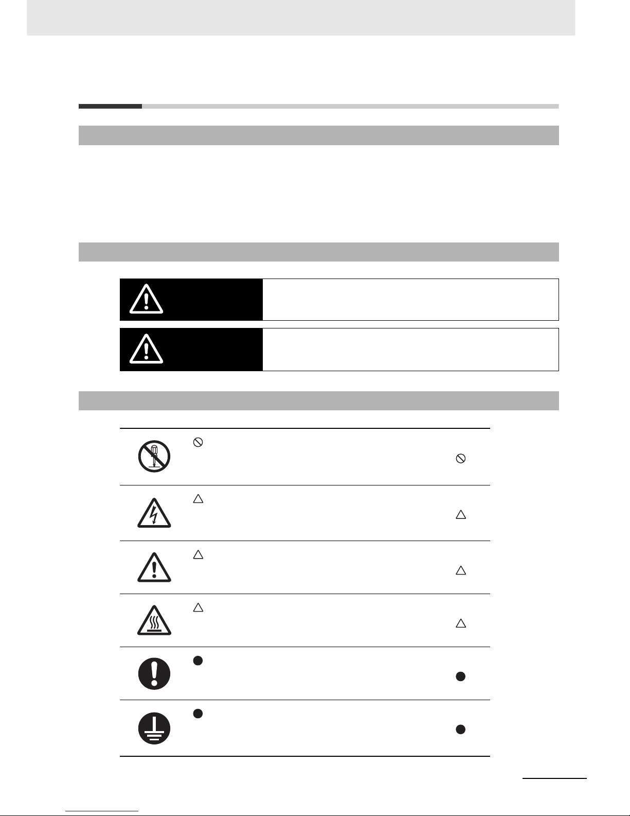
Indications and Meanings of Safety Information
Meanings of Signal Words
Indicates an imminently hazardous situation which, if not avoided, is likely to result in
serious injury or may result in death. Additionally there may be severe property
damage.
Indicates a potentially hazardous situation which, if not avoided, may result in minor
or moderate injury or in property damage.
Explanation of Symbols
This symbol indicates a prohibited item (an item you must not do).
The specific instruction is indicated using an illustration or text inside or near .
The symbol shown to the left indicates “disassembly prohibited”.
This symbol indicates danger and caution.
The specific instruction is indicated using an illustration or text inside or near .
The symbol shown to the left indicates “beware of electric shock”.
This symbol indicates danger and caution.
The specific instruction is indicated using an illustration or text inside or near .
The symbol shown to the left indicates a “non-specific general danger”.
This symbol indicates caution (including warning).
The specific instruction is indicated using an illustration or text inside or near .
The symbol shown to the left indicates “risk of hot surface”.
This symbol indicates a compulsory item (an item that must be done).
The specific instruction is indicated using an illustration or text inside or near .
The symbol shown to the left indicates a “general compulsory item”.
This symbol indicates a compulsory item (an item that must be done).
The specific instruction is indicated using an illustration or text inside or near .
The symbol shown to the left indicates “grounding required”.
WARNING
CAUTION
Page 14
Safety Precautions
12
LCD Digital Operator User’s Manual (I579)
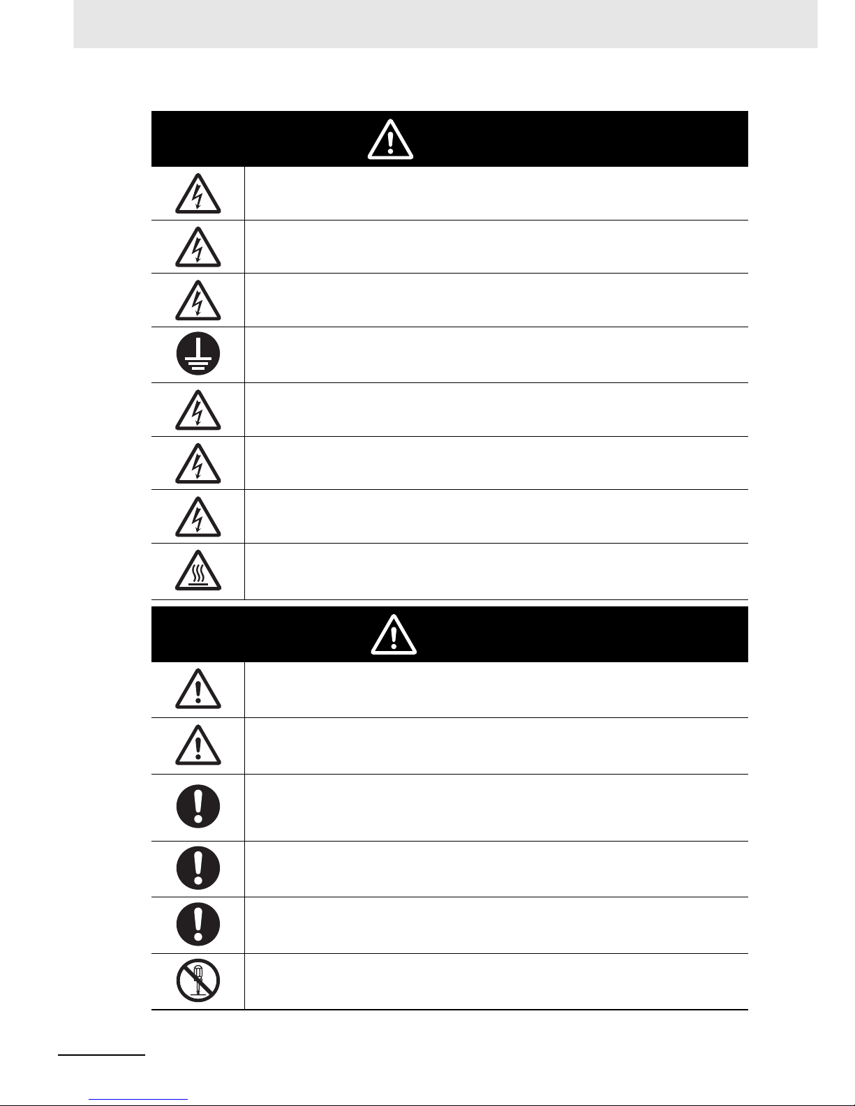
Turn off the power supply and implement wiring correctly.
Not doing so may result in a serious injury due to an electric shock.
Wiring work must be carried out only by qualified personnel.
Not doing so may result in a serious injury due to an electric shock.
Do not change wiring and slide switches (SW1), put on or take off Operator and optional devices, replace
cooling fans while the input power is being supplied. Doing so may result in a serious injury due to an
electric shock.
Be sure to ground the unit. Not doing so may result in a serious injury due to an electric shock or fire.
(200V class: type-D grounding, 400V class: type-C grounding)
Do not remove the terminal cover during the power supply and 10 minutes after the power shut off.
Doing so may result in a serious injury due to an electric shock.
Do not operate the Operator or switches with wet hands.
Doing so may result in a serious injury due to an electric shock.
Inspection of the Inverter must be conducted after the power supply has been turned off. Not doing so may
result in a serious injury due to an electric shock.
The main power supply is not necessarily shut off even if the emergency shut off function is activated.
Do not touch the Inverter fins, braking resistors and the motor, which become too hot during the power
supply and for some time after the power shut off. Doing so may result in a burn.
Do not connect resistors to the terminals (+1, P/+2, N/-) directly. Doing so might result in a small-scale fire,
heat generation or damage to the unit.
Install a stop motion device to ensure safety. Not doing so might result in a minor injury. (A holding brake is
not a stop motion device designed to ensure safety.)
Be sure to use a specified type of braking resistor/regenerative braking unit. In case of a braking resistor,
install a thermal relay that monitors the temperature of the resistor. Not doing so might result in a moderate
burn due to the heat generated in the braking resistor/regenerative braking unit. Configure a sequence that
enables the Inverter power to turn off when unusual over heating is detected in the braking resistor/
regenerative braking unit.
The Inverter has high voltage parts inside which, if short-circuited, might cause damage to itself or other
property. Place covers on the openings or take other precautions to make sure that no metal objects such
as cutting bits or lead wire scraps go inside when installing and wiring.
Take safety precautions such as setting up a molded-case circuit breaker (MCCB) that matches the
Inverter capacity on the power supply side.
Not doing so might result in damage to property due to the short circuit of the load.
Do not dismantle, repair or modify the product.
Doing so may result in an injury.
WARNING
CAUTION
Page 15

13
Precaution s for Safe Use
LCD Digital Operator User’s Manual (I579)
Precautions for Safe Use
Do not store or use the product in the following places.
• Locations subject to direct sunlight.
• Locations subject to ambient temperature exceeding the specifications.
• Locations subject to relative humidity exceeding the specifications.
• Locations subject to condensation due to severe temperature fluctuations.
• Locations subject to corrosive or flammable gases.
• Locations subject to exposure to combustibles.
• Locations subject to dust (especially iron dust) or salts.
• Locations subject to exposure to water, oil, or chemicals.
• Locations subject to shock or vibration.
• Take sufficient shielding measures when using the product in the following locations. Not doing so
may result in damage to the product.
Locations subject to static electricity or other forms of noise.
Locations subject to strong magnetic fields.
Locations close to power lines.
• If a parameter is set incorrectly when starting up, adjusting, maintaining, or replacing, an unexpected
operation may occur.
Perform the operation after enough confirmation.
• If the clock command is used in Drive Programming, an unexpected operation may occur due to
weak battery. Take measures such as detecting a weak battery by a check that the clock data returns
to the initial setting and stopping the Inverter or programs. When the LCD Digital Operator is
removed or disconnected, Drive Programming is in a waiting status by the clock command.
Installation and Storage
T ransporting, Installation, and Wiring
Operation and Adjustment
Page 16

Precautions for Safe Use
14
LCD Digital Operator User’s Manual (I579)
• When disposing of LCD digital operators and wasted batteries, follow the applicable ordinances of
your local government.
When disposing of the battery, insulate it using tape.
• Do not short + and -, charge, disassemble, heat, put into the fire, or apply strong impact on the
battery. The battery may leak, explode, produce heat or fire. Never use the battery which was applied
strong impact due to such as fall on the floor, it may leak.
• UL standards establish that the battery shall be replaced by an expert engineer.
The expert engineer must be in charge of the replacement and also replace the battery according to
the method described in this manual.
• When the display of LCD Digital Operator can not be recognized due to the service life, replace the
LCD Digital Operator.
Maintenance and Inspection
The following display must be indicated when products using lithium primary batteries (with
more than 6 ppb of perchlorate) are transport to or through the State of California, USA.
The 3G3AX-OP05 has the lithium primary battery (with more than 6 ppb of perchlorate). Label
or mark the above display on the ext erio r of all out er shi ppi ng pa ck ag es of yo ur prod uc ts when
exporting your products which the 3G3AX-OP05 are installed to the State of California, USA.
Perchlorate Material - special handling may apply.
See www.dtsc.ca.gov/hazardouswaste/perchlorate
Page 17

15
Precautions for Correct Use
LCD Digital Operator User’s Manual (I579)
Precautions for Correct Use
• Be sure to confirm the RUN signal is turned off before resetting the alarm because the machine may
abruptly start.
• Provide a separate emergency stop switch because the STOP Key on the Operator is valid only
when function settings are performed.
Retry Selection Function
Operation Stop Command
Page 18

Regulations and Standards
16
LCD Digital Operator User’s Manual (I579)
Regulations and Standards
To export (or provide to nonresident aliens) any part of this product that falls under the category of
goods (or technologies) for which an export certificate or license is mandatory according to the Foreign
Exchange and Foreign Trade Control Law of Japan, an export certificate or license (or service
transaction approval) according to this law is required.
Overseas Use
Page 19
17
Items to Check after Unpacking
LCD Digital Operator User’s Manual (I579)
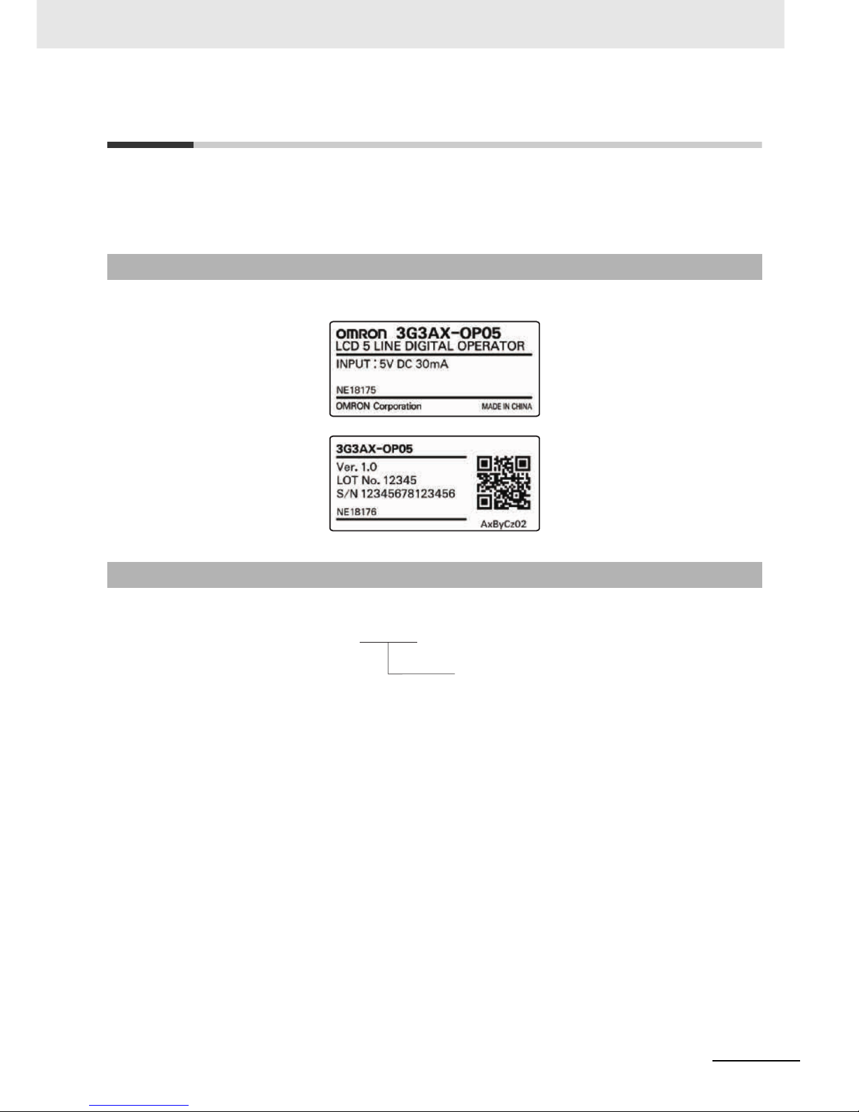
Items to Check after Unpacking
After unpacking the product, check the following items:
• Is this the model you ordered?
• Was there any damage sustained during shipment?
The product has
the following nameplate labels on its rear face
.
Checking the Nameplate
Checking the Model
3G3AX-OP 05
LCD Digital Operator
Page 20

Related Manuals
18
LCD Digital Operator User’s Manual (I579)
Related Manuals
To operate this product, you must be familiar with the equipment connected to it.
Please refer to the following manual for information on the related product.
Additional Information
For Inverter operation, please refer to the manual for the Inverter.
Name Catalog No.
RX User’s Manual I560-E2
LX User’s Manual I120E-EN
MX2 User’s Manual I570-E2
Page 21
19
Revision History
LCD Digital Operator User’s Manual (I579)
Revision History
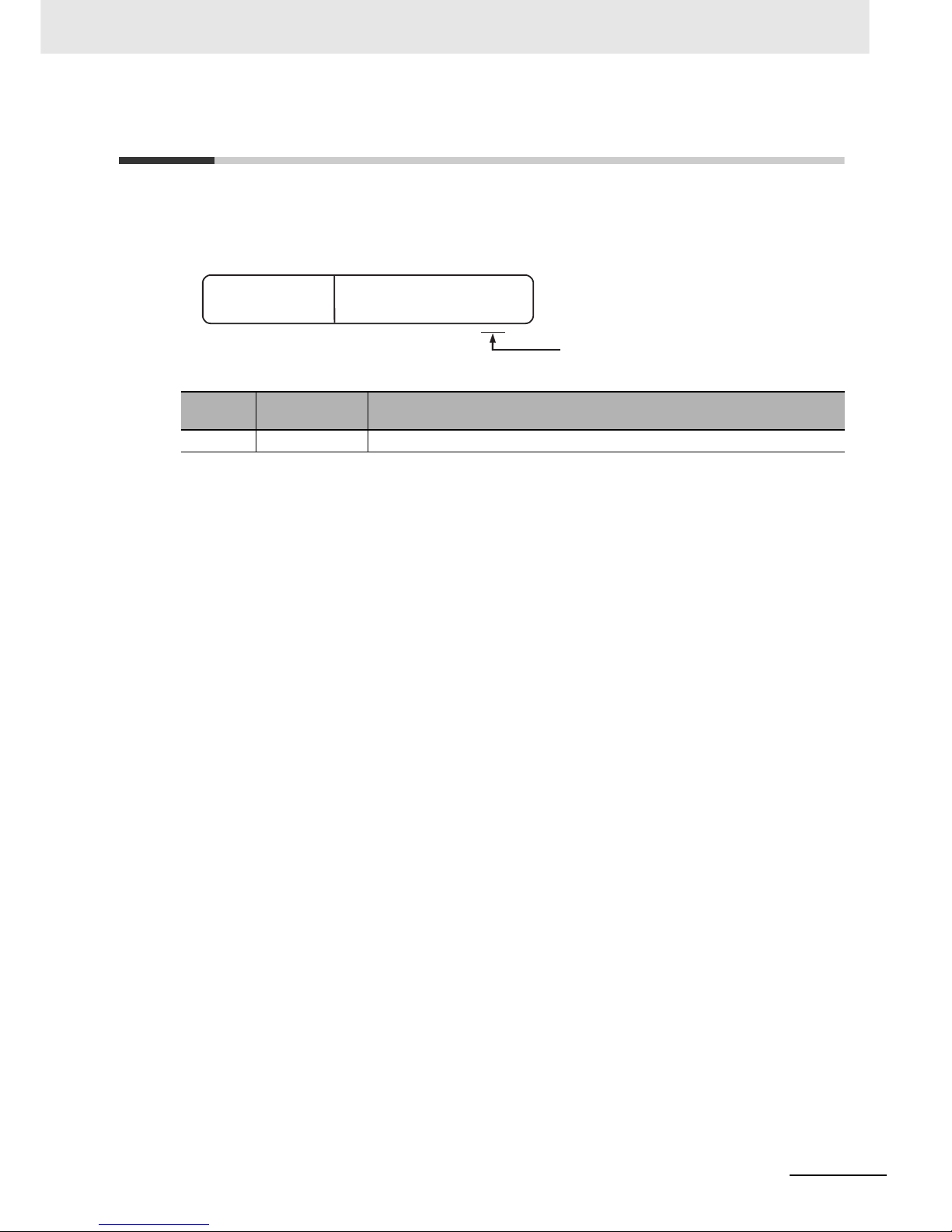
The manual revision code is a number appended to the end of the catalog number found in the bottom
right-hand corner of the front and back covers.
Example
Revision
Code
Revision Date Revised Content
01 January 2013 This manual replaces the LCD 5 Line Digital Operator Manual (I171E-EN-01)
Cat. No.
I579-E2-01
Revision code
Page 22

Revision History
20
LCD Digital Operator User’s Manual (I579)
Page 23

1 - 1
1
1
LCD Digital Operator User’s Manual (I579)
This section provides features and specifications of the LCD Digital Operator.
1-1 Features . . . . . . . . . . . . . . . . . . . . . . . . . . . . . . . . . . . . . . . . . . . . . . . . . . . . . 1-2
1-2 Supported Models . . . . . . . . . . . . . . . . . . . . . . . . . . . . . . . . . . . . . . . . . . . . . 1-4
1-3 Specifications . . . . . . . . . . . . . . . . . . . . . . . . . . . . . . . . . . . . . . . . . . . . . . . . . 1-5
1-4 External Dimensions . . . . . . . . . . . . . . . . . . . . . . . . . . . . . . . . . . . . . . . . . . . 1-6
1-5 Recommended Cables . . . . . . . . . . . . . . . . . . . . . . . . . . . . . . . . . . . . . . . . . . 1-7
Overview
Page 24

1 Overview
1 - 2
LCD Digital Operator User’s Manual (I579)
1-1 Features
This LCD Digital Operator is intended for use with the RX, LX or MX2 inverter series.
It can be connected with the RX and LX inverters directly or with the RX, LX and MX2 inverters via
cable (optional).
The LCD Digital Operator provides the following features:
A large 5-line LCD displays the name and setting range of parameters as well as the parameter
number, which improves the user’s recognition performance during parameter setting and
adjustment.
In addition, the display of up to four monitor functions enables you to check the status, adjust the
Inverter, and etc.
In case of a trip w ar ni n g, bo t h th e co d e a nd na m e of warning are displayed so tha t yo u c an pe r fo r m
early troubleshooting.
The all READ function enables to read all the parameter setting data stored in the Inverter. Up to
four sets of Inverter parameter setting data can be read and stored in the internal memory of the
LCD Digital Operator.
The parameter setting data in the memory can be all written, only if the Inverters are of the same
model and version.
Using this feature, the time for setting parameters can be reduced when the same devices are
started up or specifications are changed.
Or it is possible to store, upload and download up to a single set of Inverter parameter setting data
and a Drive Programming program.
This function enables to compare and verify parameters of the connected Inverter, Drive
Programming, and data stored in the internal memory of the LCD Digital Operator. It is useful when
checking conditions before shipment or in case of a trouble.
Using the optional cable (Model: 3G3AX-OPCN1/OPCN3) enables you to mount the LCD Digital
Operator on the surface of system panel. You can check and adjust the system status from outside
the control panel.
The LCD Digital Operator has the built-in clock function and a backup battery.
This enables the display of time information on the Current Time Monitor (d031).
This clock function is also available in the Drive Programming program.
5-Line English LCD
All Read/Write Functions for Inverter Parameters and Drive
Programming
VERIFY Function for Inverter Parameters and Drive Programming
Installation on the System Panel
Built-in Clock Function
Page 25

1 - 3
1 Overview
LCD Digital Operator User’s Manual (I579)
1-1 Features
1
Precautions for Safe Use
• If the clock command is used in Drive Programming, an unexpected operation may occur due
to weak battery. Take measures such as detecting a weak battery by a check that the clock
data returns to the initial setting and stopping the Inverter or programs. When the LCD Digital
Operator is removed or disconnected, Drive Programming is in a waiting status by the clock
command.
Precautions for Correct UsePrecautions for Correct Use
• The all WRITE function is available to write inverter parameters and Drive Programming only
with Inverters of the same model and version.
If the all WRITE function does not work, check the Inverter models and versions and, if they
are different, consider using the Inverter/Servo Parameter Support Tool CX-Drive.
Page 26

1 Overview
1 - 4
LCD Digital Operator User’s Manual (I579)
1-2 Supported Models
RX series inverter (Model: 3G3RX-).
LX series inverter (Model: 3G3LX-).
MX2 series inverter (Model: 3G3MX2-).
Page 27

1 - 5
1 Overview
LCD Digital Operator User’s Manual (I579)
1-3 Specifications
1
1-3 Specifications
Item Specification
Electrical
specifications
Input power supply
voltage
4.9 to 5.2 VDC
Transmission method RS-422 (R45)
Transmissi on rate 19.2 Kbps/4,800 bps (switching)
Environment Ambient operating
temperature
–10 to 50°C
Ambient operating
humidity
20% to 90% (with no condensation)
Ambient storage
temperature
–20 to 65°C
Location of use 1,000 m or less in height (at a place with no corrosive gas and dust)
Installation External dimensions 123 (H) x 80 (W) x 21 (D) mm
Connection type Direct or via cable (3G3AX-OPCN1/OPCN3)
Weight 0.1 kg
Display
specifications
Display Digital display on LCD (132 x 64 dots)
Display language English
Others Number of writes to
built-in EEPROM
during service life
100,000 times
Battery specifications Coin type lithium battery CR1220 (Recommended manufacturer:
Hitachi Maxell)
* Built-in real time clock backup duration: About 4 years (at 25°C)
(Including power OFF time)
Clock accuracy Error per month: –1.5 to 1.5 min
Page 28

1 Overview
1 - 6
LCD Digital Operator User’s Manual (I579)
1-4 External Dimensions
The following figures show the dimensions of LCD Digital Operator and panel cut dimensions to install.
When installing the LCD Digital Operator to the control panel, secure it from the back side using M3
screws (5 m m).
The recommended torque is 0.9 to 1.0 N·m.
80
18
2-ø4
26.5
18
2
103
6.5
External Appearance of the LCD Digital Operator Panel Cutout Diagram
Page 29

1 - 7
1 Overview
LCD Digital Operator User’s Manual (I579)
1-5 Recommended Cables
1
1-5 Recommended Cables
Use any of the following cables when installing the LCD Digital Operator separately from the RX, LX or
MX2 inverter series.
Digital Operator cables
• 3G3AX-CAJOP300-EE (Cable length: 3 m)
Page 30

1 Overview
1 - 8
LCD Digital Operator User’s Manual (I579)
Page 31

2 - 1
2
2
LCD Digital Operator User’s Manual (I579)
This section describes the part names and functions of the LCD Digital Operator.
2-1 Part Names . . . . . . . . . . . . . . . . . . . . . . . . . . . . . . . . . . . . . . . . . . . . . . . . . . . 2-2
2-2 Operation Keys . . . . . . . . . . . . . . . . . . . . . . . . . . . . . . . . . . . . . . . . . . . . . . . . 2-4
2-3 LCD Display . . . . . . . . . . . . . . . . . . . . . . . . . . . . . . . . . . . . . . . . . . . . . . . . . . 2-6
Part Names and Functions
Page 32

2 Part Names and Functions
2 - 2
LCD Digital Operator User’s Manual (I579)
2-1 Part Names
4. ALARM LED
1. POWER LED
2. RUN (Operation) LED
3. WARNING LED
7. LCD display
8. Operation keys
5. Remote LED
6. RUN command LED
indicator
10. Mounting holes
(M3: 2 positions)
9. RJ45 connector
Page 33

2 - 3
2 Part Names and Functions
LCD Digital Operator User’s Manual (I579)
2-1 Part Names
2
Precautions for Correct UsePrecautions for Correct Use
• Determine whether the operation keys (FWD RUN, REV RUN, and STOP/RESET keys) are
enabled based on the ON/OFF status of the RUN command LED indicator. Remember that
the operation keys may be enabled even when the remote LED is not lit.
• The remote LED lights only when the forced operator function is enabled by pressing the
LOCAL REMOTE key for 2 seconds or more.
Note that the remote LED does not light if the forced operator function is enabled by the
multi-function input which is set the forced operator function (OPE).
In this case, determine whether the forced operator function (OPE) is enabled based on the
status of the multi-function input terminal.
No. Name Color Description
1 POWER LED Green Lights when power is supplied to the LCD Digital Operator.
2 RUN (Operation)
LED
Green Lights during Inverter operation.
3 WARNING LED Red
Lights when the Inverter parameter settings are incorrect.
4 ALARM LED Red Lights when the Inverter trips.
5 Remote (OPE)
LED
Green Lights when the forced operator function is enabled by the
LOCAL REMOTE key. (Press the LOCAL REMOTE key for
2 seconds or more.).
6 RUN command
LED indicator
Green Lights when the RUN command is enabled on the LCD Digital
Operator. At this time, the FWD RUN, REV RUN, and
STOP/RESET keys can be used to operate the Inverter.
7 LCD display Displays various parameter settings, frequency, or other information. For
details, refer to
Section 4 Operation Procedures, Section 5 LCD Digital
Operator Related Parameters
, and
Section 6 Read/Write Functions
.
8 Operation keys These keys are u sed for display a nd setti ng. For d etails , refer to
Section 4
Operation Procedures
,
Section 5 LCD Digital Operator Related
Parameters
, and
Section 6 Read/Write Functions
.
9 RJ45 connector Connects the LCD Digital Operator with the Inverter directly or via cable
(sold separately).
10 Mounting holes Use these holes to install the LCD Digital Operator on the control panel.
Secure it from the back side using M3 screws.
Page 34

2 Part Names and Functions
2 - 4
LCD Digital Operator User’s Manual (I579)
2-2 Operation Keys
No. Key image Name Function
1
LOCAL REMOTE
key
Switches between the Local and Remote modes. If the key is
pressed for 2 seconds or more, the mode is switched; from
Local to Remote or from Remote to Local. When the LCD
Digital Operator is in the Local mode, the Remote (OPE) LED
is lit. Use the Local mode to operate the Inverter using the
LCD Digital Operator’s operation keys (FWD RUN, REV RUN,
and STOP/RESET).
2 READ key
Reads all the parameter setting data into the LCD Digital
Operator’s memory. For details, refer to Section 5 LCD Digital
Operator Related Parameters.
3WRITE key
Copies a single set of Inverter parameter setting data, or a
single set of Inverter parameter setting data and a Drive
Programming program, stored on the LCD Digital Operator
into the Inverter. For details, refer to Section 5 LCD Digital
Operator Related Parameters.
4 ESC key
Returns to a screen in the one level higher layer.
If pressed during a parameter change, the LCD Digital
Operator displays the previous screen with the change
cancelled.
5Enter key
Brings you forward to the screen that is one level lower in the
hierarchy.
If pressed during a parameter change, the LCD Digital
Operator displays the previous screen with the change fixed
and stored.
6Increment key
Moves the cursor up.
It is also used to increase the param eter numbe r or param eter
value.
Operation keys
Page 35

2 - 5
2 Part Names and Functions
LCD Digital Operator User’s Manual (I579)
2-2 Operation Keys
2
*1 Check the KEY ENABLED indicator (RUN command LED indicator).
Precautions for Safe Use
• Provide a separate emergency stop switch because the STOP key on the operator is valid
only when function settings are performed.
• The FWD RUN, REV RUN, and STOP/RESET keys are disabled while the Inverter parameter
settings are all read or written. Perform the all read/write functions during Inverter stop.
7 Decrement key
Moves the cursor do wn.
It is also used to decre ase the para meter number or p arameter
value.
8 PREV PAGE key
Moves the cursor to the left.
In Navigation lev el dis play mo de, mo ves to the pre vious mode .
9 NEXT PAGE key
Moves the cursor to the right.
In Navigation level display mode, moves to the next mode.
10
FWR RUN key
*1
Runs the motor in the forward direction.
This key is enabled in the following cases.
• The remote mode is enabled by pressing the LOCAL
REMOTE key for 2 seconds (the remote LED is lit).
•
RUN Command Selection (A002) is set to “02: Digital
operator”.
•
The forced operator function is enabled by the multi-func tion
input which is set the forced operator function (OPE).
11
REV RUN key
*1
Runs the motor in the reverse direction.
This key is enabled in the following cases.
•
The remote mode is enabled by pressing the LOCAL
REMOTE key for 2 seconds (the remote LED is lit).
•
RUN Command Selection (A002) is set to “02: Digital
operator”.
•
The forced operator function is enabled by the multi-func tion
input which is set the forced operator function (OPE).
12 STOP/RESET key
Stops the motor, or resets the alarm.
When the parameter b087 (Stop key selection) is set to “01:
Disable,” this key is enabled in the following cases only.
•
The remote mode is enabled by pressing the LOCAL
REMOTE key for 2 seconds (the remote LED is lit).
•
RUN Command Selection (A002) is set to “02: Digital
operator”.
•
The forced operator function is enabled by the multi-func tion
input which is set the forced operator function (OPE).
No. Key image Name Function
Page 36

2 Part Names and Functions
2 - 6
LCD Digital Operator User’s Manual (I579)
2-3
LCD Display
The LCD display has two backlight colors; white and orange.
The color of the backlight indicates the state of the Inverter, as shown in the following table.
The first line of LCD display always shows the display mode, the selected motor, the Inverter RUN
status, and the display selection.
Backlight
Backlight color State
White Normal (No relation to the RUN/Stop state of the Inverter)
Orange Warning (Parameter mismatch)
White/Orange
(Flashing alternately at intervals of 1 second)
Trip (Same as the ALARM LED)
LCD Display
Item Display item Description
Display mode
MONITOR-A Monitor Mode A
MONITOR-B Monitor Mode B
FUNCTION Function Mode
TRIP Trip Mode (Error)
WARNING Warning Mode (Warning)
READ Read Mode
WRITE Write Mode
OPTION Option Mode
Control target No.
M1 1st control (Normal)
M2 2nd control (allocate Multi-function Input S1 to S8
Selection (C001 to C008) to
“08: SET” and turn ON to
switch)
M3 3rd control (allocate Multi-function Input S1 to S8
Selection (C001 to C008) to “17: SET3” and turn ON to
switch)
Control target No.
Display mode
Inverter RUN status
Display selection
Page 37

2 - 7
2 Part Names and Functions
LCD Digital Operator User’s Manual (I579)
2-3 LCD Display
2
Inverter RUN status
STOP Stop
FWD Forward
REV Reverse
Setting in b037
(Display Selection)
ALL Complete display
UTL Individual display of functions
USR User setting display
CMP Data comparison display
BAS Basic display
Item Display item Description
Page 38

2 Part Names and Functions
2 - 8
LCD Digital Operator User’s Manual (I579)
Page 39

3 - 1
3
3
LCD Digital Operator User’s Manual (I579)
This section provides information on the installation and wiring of the LCD Digital
Operator.
3-1 Installation on the Inverter . . . . . . . . . . . . . . . . . . . . . . . . . . . . . . . . . . . . . . 3-2
3-1-1 Direct Installation on the Inverter (RX, LX models) . . . . . . . . . . . . . . . . . . . . . 3-3
3-1-2 Installation on the Inverter via Cable (RX, LX, MX2 models) . . . . . . . . . . . . . . 3-4
3-1-3 Checking the Operation After Installation . . . . . . . . . . . . . . . . . . . . . . . . . . . . 3-5
3-1-4 Date and Time Setting . . . . . . . . . . . . . . . . . . . . . . . . . . . . . . . . . . . . . . . . . . . 3-6
3-1-5 Other Settings . . . . . . . . . . . . . . . . . . . . . . . . . . . . . . . . . . . . . . . . . . . . . . . . . 3-6
Installation and Wiring
Page 40

3 Installation and Wiring
3 - 2
LCD Digital Operator User’s Manual (I579)
3-1 Installation on the Inverter
This section shows how to install the LCD Digital Operator on the RX, LX and MX2 inverter series.
The installation procedure differs with installation methods. This section describes the following
2 methods.
• Direct installation on the Inverter
• Installation on the Inverter via cable
Precautions for Correct UsePrecautions for Correct Use
• Shut off the power supply to the Inverter before installing or removing the LCD Digital
Operator. Not doing so may result in failure.
• The LCD Digital Operator cannot be installed directly on an Inverter that is already mounted
with a Communications Unit.
Section Title Description
3-1-1 Direct installation on the Inverter Describes the procedure for installing the LCD Digital Operator
directly on the Inverter.
3-1-2 Installation on the Inverter via
Cable
Describes the pro cedure for i nst alling the LCD D igit al Operat or on
the Inverter via cable in situations where:
• The LCD Digital Operator is installed on the control panel.
• The use of a Communications Unit prev en t s dire ct ins tallation
on the Inverter.
Page 41

3 - 3
3 Installation and Wiring
LCD Digital Operator User’s Manual (I579)
3-1 Installation on the Inverter
3
3-1-1 Direct Installation on the Inverter (RX, LX models)
This section describes the procedure for installing the LCD Digital Operator directly on the Inverter.
Precautions for Correct UsePrecautions for Correct Use
The LCD Digital Operator cannot be installed directly on an Inverter that is already mounted with
a Communications Unit.
1
Remove the Digital Operator and the spacer cover
from the Inverter.
2
Install the LCD Digital Operator on the Inverter.
Additional Information
To facilitate installation, raise the connector of the Inverter and push the LCD Digital Operator
into the Inverter.
3-1-1 Direct Installatio n on the Inv e rt e r (RX, LX models)
Page 42

3 Installation and Wiring
3 - 4
LCD Digital Operator User’s Manual (I579)
1
If necessary, mount theLCD Digital
Operator to the pane l. Cut out the p anel
according to the panel cutout diagram
and, using M3 screws, secure the LCD
Digital Operator to the panel from the
back side.
The recommended torque is 0.9 to 1.0
N·m.
For panel cutout dimensions, refer to
1-4 External Dimensions on page 1-6.
2
Connect the LCD Digital Operator with the
Inverter via cable.
• Recommended cable model:
3G3AX-CAJOP300-EE (Cable length: 3 m)
3-1-2 Installation on the Inverter via Cable (RX, LX, MX2 models)
Page 43

3 - 5
3 Installation and Wiring
LCD Digital Operator User’s Manual (I579)
3-1 Installation on the Inverter
3
3-1-3 Checking the Operation After Installation
After checking that the system and surrounding areas are safe, turn ON the power supply to the
Inverter.
Check the LCD Digital Operator display.
The installation is completed successfully if the following Monitor screen is displayed.
However, when the power is supplied to the LCD Digital Operator for the first time after purchase, when
the built-in battery is consumed, or when the power supply is turned on for the first time after battery
replacement, the following screen appears, which prompts you to set the clock. If this screen is
displayed, press the ESC key to move to the normal screen and perform the Date and Time setting
from the OPTION MODE menu. For the Date and Time setting, refer to 3-1-4 Date and Time Setting on
page 3-6.
The LCD Digital Operator may display the COM ERROR screen, or the Read & Copy only screen when
the power is supplied. In this case, choose INV Type Select from the OPTION MODE menu and set the
type of the Inverter to be used.
For details, refer to 5-1-2 Details of Each Option Mode Parameter on page 5-4.
Precautions for Correct UsePrecautions for Correct Use
• The LCD Digital Operator can be used without configuring the Date and Time setting.
However, if the clock command is used in Drive Programming, configure the Date and Time
setting. Not doing so may result in an unexpected operation due to the lack of the correct date
and time information.
• The available display language is only English on this LCD Digital Operator. Be sure to set
the Language option to “01: English”.
If the language display is abnormal, check from the OPTION MODE menu to be sure that the
Language is set to “01: English”.
For details, refer to 5-1-1 Operation in the Option Mode on page 5-2.
3-1-3 Checking the Operation After Installation
Page 44

3 Installation and Wiring
3 - 6
LCD Digital Operator User’s Manual (I579)
If the screen, which prompts you to set the clock, appears as shown below, press the ESC key to return
to the normal screen
and simultaneously press the , , and keys to enter the Option Mode.
Select Date and Time by pressing the key to set the current date and time.
Additional Information
The screen, which prompts you to set the clock, disappears automatically in 3 minutes after the
power supply is turned on.
Change the LCD Digital Operator settings (in the Option Mode) and Inverter parameter settings as
required.
For details about changing the parameter settings, refer to Section 5 LCD Digital Operator Related
Parameters.
3-1-4 Date and Time Setting
3-1-5 Other Settings
Page 45

4 - 1
4
4
LCD Digital Operator User’s Manual (I579)
This section provides an overview of the display modes supported by LCD Digital
Operator and how to operate the LCD Digital Operator in each display mode.
For the Option Mode, refer to Section 5 LCD Digital Operator Related Parameters. For
the Read/Write Mode, refer to Section 6 Read/Write Functions.
4-1 Overview of Display Modes . . . . . . . . . . . . . . . . . . . . . . . . . . . . . . . . . . . . . . 4-2
4-1-1 Transition of Screens . . . . . . . . . . . . . . . . . . . . . . . . . . . . . . . . . . . . . . . . . . . . 4-2
4-1-2 Overview of Each Mode . . . . . . . . . . . . . . . . . . . . . . . . . . . . . . . . . . . . . . . . . . 4-3
4-1-3 Changing the Display in Each Mode . . . . . . . . . . . . . . . . . . . . . . . . . . . . . . . . 4-5
4-2 Operation in the Monitor Mode A . . . . . . . . . . . . . . . . . . . . . . . . . . . . . . . . . 4-6
4-3 Operation in the Monitor Mode B . . . . . . . . . . . . . . . . . . . . . . . . . . . . . . . . . 4-7
4-4 Operation in the Function Mode . . . . . . . . . . . . . . . . . . . . . . . . . . . . . . . . . . 4-8
4-5 Operation in the Trip Mode . . . . . . . . . . . . . . . . . . . . . . . . . . . . . . . . . . . . . . 4-9
Operation Procedures
Page 46

4 Operation Procedures
4 - 2
LCD Digital Operator User’s Manual (I579)
4-1 Overview of Display Modes
The basic display screens of LCD Digital Operator are displayed in four modes as shown below.
Each mode has two levels: the higher Navigation level and the lower Edit level. The user can move
between each mode in the Navigation level only.
• Monitor Mode A: The mode to display and set a single monitor function and a single parameter
function.
• Monitor Mode B: The mode to display up to four monitor functions on a single screen.
• Function
Mode
: The
mode
to set parameter settings. The screen also displays the
parameter
name
and setting range.
• Trip Mode: The mode to display the trip and warning information.
In addition to the above, the LCD Digital Operator has the following three called modes. At any of the
above levels and in any operating state, you can call these modes by pressing the key(s) shown to the
right of the down arrow above each screen, as shown on the next page. After calling these screens, you
can press the ESC key to restore the operating state before the call.
• All Read: The mode to read all Inverter parameter settings and Drive Programming data from the
Inverter.
• All Write: The mode to write all Inverter parameter setting and Drive Programming data to the
Inverter.
• Option Mode: The mode to set the LCD Digital Operator.
4-1-1 Transition of Screens
Navigation levelEdit level
Monitor
Mode A
Monitor
Mode B
Function
Mode
Trip
Mode
Select the monitor item.
Select the setting item.
Select the setting
line.
Select the setting
item.
Monitor the overall
trip history.
Monitor
Mode A
Monitor
Mode B
Function
Mode
Trip
Mode
Monitor
Mode A
Monitor
Mode B
Function
Mode
Change the set value. Change the set value. Change the set value.
Page 47

4 - 3
4 Operation Procedures
LCD Digital Operator User’s Manual (I579)
4-1 Overview of Display Modes
4
4-1-2 Overview of Each Mode
In this mode, one “d” group Inverter monitor function and one
“F to U” group Inverter parameter are displayed on the same
screen.
The content of “d” group Inverter monitor function is displayed
in a large font size. The parameter number such as “F001” and
the content of “F to U” parameter are displayed without the
function name.
In this mode, four “d” group Inverter
monitor functions can be displayed on the same screen.
At this time, the parameter numbers are not displayed.
These modes can be called at any level and in any operating state.
Press the ESC key to restore the operating state before the call.
4-1-2 Overview of Each Mode
Monitor Mode A
Monitor Mode B
Read
Mode
Write
Mode
Option
Mode
Option
Mode
Option
Mode
Change the set values of
the LCD Digital Operator.
Select the setting item.
Press three keys
simultaneously.
Page 48

4 Operation Procedures
4 - 4
LCD Digital Operator User’s Manual (I579)
In this mode, “F to U” group Inverter parameters can be
displayed and set.
The screen shows the parameter number, function name,
parameter data and setting range of the parameter.
Precautions for Correct UsePrecautions for Correct Use
In the Function Mode, “d” group Inverter monitor functions cannot be displayed and set.
Trip information and warning information are displayed in this
mode.
If a trip or a warning occurs in the Inverter, the trip screen is
displayed from any display mode.
In the Option Mode, Read Mode, and Write Mode, the trip
screen is not displayed even if an Inverter trip or warning
occurs.
The ALARM or WARNING LED lights up.
In this mode, a single set of Inverter parameter settings, or a
single set of parameter settings and a Drive Programming
program, can be all read and stored in the LCD Digital
Operator.
Select a single set or four sets of storage data by 5. R/W
Storage Mode in the OPTION MODE menu.
For details about the Read Mode, refer to Section 6
Read/Write Functions.
Function Mode
Trip Mode
Read Mode
Case: 5. R/W Storage Mode = “01 :Single”
Case: 5. R/W Storage Mode = “02: Quad”
Page 49

4 - 5
4 Operation Procedures
LCD Digital Operator User’s Manual (I579)
4-1 Overview of Display Modes
4
4-1-3 Changing the Display in Each Mode
In this mode, the Inverter parameter settings and
Drive Programming program data stored in the LCD
Digital Operator can be all written to the Inverter.
Change the number of storage data by selecting 5. R/W
Storage Mode in the OPTION MODE menu.
For details about the Write Mode, refer to Section 6
Read/Write Functions.
In this mode, the parameter settings of the LCD Digital Operator can be set and changed.
This mode supports the following settings of the LCD Digital
Operator.
1. Language
2. Date and Time
3. Read Lock
4. INV Type Select
5. R/W Storage Mode
6. Backlight Auto-off
7. Backlight Flicker
8. Operator Reset
9. Check Mode
For details about the Option Mode, refer to Section 5 LCD Digital Operator Related Parame ters.
Each display mode can be switched by pressing the or key in the Navigation level.
In each mode, press the key to move to the Edit level and press the key to move to the
Navigation level. To move to the Read or Write Mode, press the or key.
To move to the Option Mode, press the , , and keys simultaneously.
For the transition between display modes, refer to the figure in 4-1-1 T ransition of Screens on page 4-2.
Write Mode
Option Mode
4-1-3 Changing the Display in Each Mode
Case: 5. R/W Storage Mode = “01 :Single”
Case: 5. R/W Storage Mode = “02: Quad”
Page 50

4 Operation Procedures
4 - 6
LCD Digital Operator User’s Manual (I579)
4-2 Operation in the Monitor Mode A
1
At the Navigation level, press the or
key to select the Monitor Mode A (MONITOR-A)
screen.
Press the key to show the cursor on the “d”
group monitor function.
2
Press the or key to select th e mo n it o r
function to display on the MONITOR-A screen.
Select the parameter number c orre sponding to th e
monitor function to display.
• Press the key to return to the Navigation
level.
3
To move the cursor position displayed on the
screen, press the or key.
When the cursor moves to the Inverter parameter
number displayed on the last line (in this case,
F001), you can change the parameter number by
the or key.
• Press the key to return to the Navigation
level.
4
After changing the Inverter parameter number,
press the key to move the cursor to the
parameter data position.
Change the parameter data using the or
key.
• To save the change, press the key. The cursor returns to the parameter number.
• To cancel the change, press the key.
The cursor returns to the parameter number.
Press the key to return to the Navigation level.
,
Page 51

4 - 7
4 Operation Procedures
LCD Digital Operator User’s Manual (I579)
4-3 Operation in the Monitor Mode B
4
4-3 Operation in the Monitor Mode B
1
At the Navigation level, press the or
key to select the Monitor Mode B (MONITOR-B)
screen.
2
Press the key to show the cursor in the first
parameter line of the “d” group monitor function.
Press the or key to move between the
four inverter parameters.
• Press the key to return to the Navigation
level.
3
Select the parameter to change and press the
key.
The cursor moves to the parameter number of the
selected “d” group monitor function.
Press the or key to select the
parameter number to monitor.
• To register the parameter number, press the key.
The screen returns to the parameter display screen.
• To cancel the change, press the key. The screen returns to the parameter display
screen.
• Press the key again to return to the Navigation level.
or
Page 52

4 Operation Procedures
4 - 8
LCD Digital Operator User’s Manual (I579)
4-4 Operation in the Function Mode
1
At the Navigation level, press the or
key to select the Function Mode screen.
2
Press the key. The cursor moves to the
parameter number. Then, press the , ,
, or key to select the parameter No. to
change.
• Press the key to return to the Navigation
level.
3
Press the key . The cursor is now placed over
the parameter data. Press the or key
to select the value to set.
• To save the parameter val ue, press the key.
When saved, the cursor moves to the parameter
number.
• To cancel the change, press the key. The cursor moves to the parameter number.
or
Page 53

4 - 9
4 Operation Procedures
LCD Digital Operator User’s Manual (I579)
4-5 Operation in the Trip Mode
4
4-5 Operation in the Trip Mode
1
At the Navigation level, press the or
key to select the Trip Mode screen.
2
Press the key to show the information on the
past trips (six trip errors) recorded in the Inverter
and the information on the warning (one warning).
The information on one trip error comprises two pages.
To switch from page 1 (P1) to page 2 (P2),
press the or key.
To display the information on the past six trip errors,
press the or key.
3
If you press the key when ERR1 is displayed
or press the key when ERR6 is displayed,
the screen switches to the Warning Mode.
Precautions for Correct UsePrecautions for Correct Use
If a trip occurs, the ALARM LED lights up. Then, press the key to reset the Inverter.
Page 54

4 Operation Procedures
4 - 10
LCD Digital Operator User’s Manual (I579)
Page 55

5 - 1
5
5
LCD Digital Operator User’s Manual (I579)
This section describes the Inverter parameters related to the LCD Digital Operator.
5-1 Parameter Setting . . . . . . . . . . . . . . . . . . . . . . . . . . . . . . . . . . . . . . . . . . . . . 5-2
5-1-1 Operation in the Option Mode . . . . . . . . . . . . . . . . . . . . . . . . . . . . . . . . . . . . . 5-2
5-1-2 Details of Each Option Mode Parameter . . . . . . . . . . . . . . . . . . . . . . . . . . . . . 5-4
5-2 Related Inverter Parameters . . . . . . . . . . . . . . . . . . . . . . . . . . . . . . . . . . . . . 5-6
LCD Digital Operator Related
Parameters
Page 56

5 LCD Digital Operator Related Parameters
5 - 2
LCD Digital Operator User’s Manual (I579)
5-1 Parameter Setting
The LCD Digital Operator parameters can be set and changed in the Option Mode.
The Option Mode provides the following nine settings:
1. Language
2. Date and Time
3. Read Lock
4. INV Type Select
5. R/W Storage Mode
6. Backlight Auto-off
7. Backlight Flicker
8. Operator Reset
9. Check Mode
The next section describes how to operate in the Option Mode.
1
Press the , , and keys
simultaneously to enter the Option Mode.
The cursor appears in the first line of the OPTION
MODE menu. Press the or key to move
between the OPTION MODE menu.
To return to the Navigation level, press the key.
2
Select Language and press the key. The
cursor moves to the Language setting.
Press the or key to change the set
value.
• To save the change, press the key. The
screen returns to the OPTION MODE menu.
• To cancel the change, press the key.
The screen returns to the OPTION MODE menu.
Precautions for Correct UsePrecautions for Correct Use
The available display language is only English on this LCD Digital Operator. Even if other
language is set, the screen is displayed in English.
In the Language setting, always select “01: English”.
5-1-1 Operation in the Option Mode
or
Page 57

5 - 3
5 LCD Digital Operator Rela ted Parameters
LCD Digital Operator User’s Manual (I579)
5-1 Parameter Setting
5
5-1-1 Operation in the Option Mode
3
Press the to move the cursor over 2. Date
and Time in the second line.
4
In 2. Date and Time, press the key. The
cursor moves over the date and time data.
Press the or key to move among the day,
month, year, and time data. When the cursor is placed
over any of these data, you can change the value by
the or key.
• To save the change, press the key. The screen returns to the OPTION MODE menu.
• To cancel the change, press the key. The screen returns to the OPTION MODE menu.
or
Page 58

5 LCD Digital Operator Related Parameters
5 - 4
LCD Digital Operator User’s Manual (I579)
The table below shows the setting of each Option Mode item.
5-1-2 Details of Each Option Mode Parameter
Item Description Setting range Default
1. Language Select the display language. 01: English 01
2. Date and
Time
Set the date and time for the LCD Digital
Operator.
* On the screen, move the cursor over the
Format number and select the desired
format (1 to 3).
Format 1: (YYYY/MM/DD)
Date: 2000/01/01 to
2099/12/31
Time: 00:00 to 23:59
Format 2: (MM/DD/YYYY)
Date: 01/01/2000 to
12/31/2099
Time: 00:00 to 23:59
Format 3: (DD/MM/YYYY)
Date: 01/01/2000 to
31/12/2099
Time: 00:00 to 23:59
2009/01/01
THU 00:00
Format 1
3. Read Lock Select this to protect the parameter settings
stored in the LCD Digital Operator from
overwriting.
01: Enable
02: Disable
02
4. INV Type
Select
Select the type of the Inve rter used with this
LCD Digital Operator. If the set Inverter type
does not match the Inverter actually
connected, the LCD Digital Operator will
display “COM ERROR” automatically.
01: Type 1
(All models)
02: Type 2
(Do not set)
01
5. R/W Storage
Mode
Select a single set or four sets of Inverter
parameters to store in the LCD Digit a l
Operator’s internal memory. Setting this to
“01: Single” facilitates the operability and is
effective for writing to more than one
Inverter. For details, refer to Section 6
Read/Write Functions.
01: Single
(Single set of parameter
settings and one Drive
Programming program)
02: Quad
(Four sets of parameter
settings)
02
6. Backlight
Auto-off
Set the Backlight Auto-off function. The
backlight of LCD Digital Operator
automatically turns off if any key is not
pressed for 1 minute.
The backlight will light up again if you press
any key.
The Backlight Auto-off function will not work
if a trip occur.
01: Off (Disable)
02: 1 minute
01
Page 59

5 - 5
5 LCD Digital Operator Rela ted Parameters
LCD Digital Operator User’s Manual (I579)
5-1 Parameter Setting
5
5-1-2 Details of Each Option Mode Parameter
Precautions for Correct UsePrecautions for Correct Use
• The applicable Language option is “01: English” only.
The LCD Digital Operator may not provide the expected operation with other settings.
• Do not enable the EEPROM check. If you perform the EEPROM check, the data (parameter
setting and Drive Programming program data) stored in the LCD Digital Operator will be lost.
7. Backlight
Flicker
Set this to enable or disable the orange
backlight illumination.
01: Enable
02: Disable
01
8. Operator
Reset
Use this function to reset the LCD Digital
Operator to its default settings .
The following items will be reset:
1) Language: English
2) Date and Time:
2009/01/01 THU 00:00
3) Time Format: 01: YY/MM/DD
4) Read Lock: Disable
5) R/W Stora ge Mo de: Quad
6) Backlight Auto-off: Off
7) Backlight Flicker: Enable
After resetting the LCD Digital Operator, you
need to perf orm the Date and Time setting
again.
01: YES
02: NO
02
9. Check Mode Select this to check whether the LED s, ke ys
etc. work normally.
1: Key&Led Check
2: Lcd Check
3: RTC Check
4: EEPROM Check
5: Serial Loopback
6: Debug Mode
7: Firmware Version
–
Item Description Setting range Default
Page 60

5 LCD Digital Operator Related Parameters
5 - 6
LCD Digital Operator User’s Manual (I579)
5-2 Related Inverter Parameters
The table below shows the RX and MX2 Inverter parameters related to the LCD Digital Operator.
For details, please refer to RX (I560-E2) or MX2 (I570-E2) User’s Manuals.
*1 Setting b166 (Data Read/Write Selection) to “01: R/W protected” disables the all read/write functions and thus data
cannot be read/written from the LCD Digital Operator.
Parameter No. Function name Data
Default
value
Unit
b031 Soft Lock Selection
00: Data other than b031 cannot be changed when
terminal SFT is ON.
01: Data other than b031 and set freque nc y c an not be
changed when terminal SFT is ON.
02: Data other than b031 cannot be changed.
03: Data other than b031 and set freque nc y c an not be
changed.
10: Data can be changed during RUN.
01 –
b037 Display Selection 00: Complete display
01: Individual display of functions
02: User setting + b037
03: Data comparison display
04: Basic display
00 –
b038 Initial Screen Selection
000: Screen on w hich the Enter key was last pressed
001 to 060: d001 to d060
201: F001
202: Do not set
001 –
b087 STOP Key Selection 00: Enable
01: Disable
02: Only resetting enabled
00 –
b166 Data Read/Write
Selection
*1
00: R/W OK
01: R/W protected
00 –
Page 61

5 - 7
5 LCD Digital Operator Rela ted Parameters
LCD Digital Operator User’s Manual (I579)
5-2 Related Inverter Parameters
5
The table below shows the LX Inverter parameters related to the LCD Digital Operator.
For details, please refer to LX (I120E-EN) User’s Manual.
Parameter No. Function name Data
Default
value
Unit
F010 STOP Key Enable 00: Enable
01: Disable
02: Reset (disabling only the function to stop)
00 –
F011 Function Code Display
Restriction
00: ALL (full display)
01: FUNCTION (function-specific display)
02: USER (user setting)
03: COMPARE (data comparison display)
05: MONITOR (monitor only displ ay )
00 –
F013 Soft Lock Selection 00: MD0 (disabling change of data other than “F013”
when SFT is ON)
01: MD1 (disabling change of data other than “F013”
and frequency settings when SFT is ON)
02: MD2 (disabling change of data other than “F013”)
03: MD3 (disabling change of data other “F013” and
frequency settings)
00 –
F014 Copy Function Enable 00: Disable
01: Enable
00 –
Page 62

5 LCD Digital Operator Related Parameters
5 - 8
LCD Digital Operator User’s Manual (I579)
Page 63

6 - 1
6
6
LCD Digital Operator User’s Manual (I579)
This section describes how to read and write Inverter parameter settings using the LCD
Digital Operator.
6-1 Single READ Function . . . . . . . . . . . . . . . . . . . . . . . . . . . . . . . . . . . . . . . . . . 6-2
6-2 Single WRITE Function . . . . . . . . . . . . . . . . . . . . . . . . . . . . . . . . . . . . . . . . . 6-3
6-3 Quad READ Function . . . . . . . . . . . . . . . . . . . . . . . . . . . . . . . . . . . . . . . . . . . 6-4
6-4 Quad VERIFY Function . . . . . . . . . . . . . . . . . . . . . . . . . . . . . . . . . . . . . . . . . 6-6
6-5 Quad WRITE Function . . . . . . . . . . . . . . . . . . . . . . . . . . . . . . . . . . . . . . . . . . 6-8
6-6 Conditions for the Read/Write Operations . . . . . . . . . . . . . . . . . . . . . . . . 6-10
Read/Write Functions
Page 64

6 Read/Write Functions
6 - 2
LCD Digital Operator User’s Manual (I579)
6-1 Single READ Function
The Single READ function is enabled when 5. R/W Storage Mode in the OPTION MODE menu is set to
“01: Single”.
The Single Read function is executed immediately just by pressing the key.
The Single READ function reads a single set of Inverter parameter setting data and a Drive
Programming program and stores them to the LCD Digital Operator. When reading is completed, the
screen returns to the previous screen.
This is time-saving when you need to repeat the all read/write operations.
Precautions for Correct UsePrecautions for Correct Use
• The Single READ function cannot be executed by pressing the key in the Write Mode
or Option Mode.
Use this function in other modes.
• The Single READ function overwrites the data existing in the LCD Digital Operator because its
memory is set to store a single set of Inverter data.
• This function attempts to read a Drive Programming program even when it is not stored in the
Inverter. At that time, it stores the status of no Drive Programming program.
After a read operation is completed, the screen
returns to the previous screen automatically.
Reading parameter setting
data
Reading a Drive
Programming program
Automatic
transition
Automatic
transition
Reading completed
Page 65

6 - 3
6 Read/Write Functions
LCD Digital Operator User’s Manual (I579)
6-2 Single WRITE Function
6
6-2 Single WRITE Function
The Single WRITE function is enabled when 5. R/W Storage Mode in the OPTION MODE menu is set
to “01: Single”.
The Single WRITE function is executed immediately just by pressing the key.
The Single WRITE function writes a single set of Inverter parameter setting data and a Drive
Programming program stored in the LCD Digital Operator to the connected Inverter.
When writing is completed, the screen returns to the previous screen.
This is time-saving when you need to repeat the all read/write operations.
Precautions for Correct UsePrecautions for Correct Use
• The Single WRITE function cannot be executed by pressing the key in the READ Mode
or Option Mode.
Use this function in other modes.
• The Single WRITE function is available only with Inverters of the same model and of the same
version.
If the all WRITE function does not work, check the Inverter models and versions and, if they
are different, consider using the Inverter/Servo Parameter Support Tool CX-Drive.
After write operation is completed, the screen
returns to the previous screen in 2 seconds.
Writing parameter setting
data
Writing a Drive Programming
program
Automatic
transition
Automatic
transition
Writing completed
Page 66

6 Read/Write Functions
6 - 4
LCD Digital Operator User’s Manual (I579)
6-3 Quad READ Function
The Quad READ function is enabled when 5. R/W S torage M ode in the OP TION M ODE menu is set to “02: Quad”.
The Quad READ function provides the following two operations.
• Reads a single set of all Inverter parameter setting data and stores up to four sets in the specified
memory number 1 to 4.
• Reads a single set of all Inverter parameter setting data and a Drive Programming program, and
stores the data in the memory number 1. At this time, the Drive Programming program is stored in the
other three sets of internal memory.
Press the key. When the READ screen appears, select the memory number to store the data.
Press the key. The Select data is displayed. Select one of the following operations to execute
and press the key again.
01: Read Data (reads a single set of all Inverter parameter setting data)
02: Read Data+EzSQ (reads a single set of all Inverter parameter setting data and a Drive
Programming program)
05: Cancel (cancels the read operation)
When reading i s c ompleted, the screen returns to the previo us screen.
For the Quad VERIFY function, refer to 6-4 Quad VERIFY Function on page 6-6.
Note In the LCD Digital Operator, the Drive Programming is named as “EzSQ”.
When no Inverter parameter sett ing data is stored in the LCD Digital Operator,
“--” is shown.
For selection of number to store the Inverter parameter setting data, press the
or key to move the cursor and press the key to fix.
After pressing the key, you can select one of the following operations
under Select data.
01: Read data (reads parameter setting data)
02: Read data+EzSQ (reads parameter setting data and a Drive
Programming program)
03: Verify dat a (ve rifies parameter setting data)
04: Verify EzSQ (verifies a Drive Programming program)
05: Cancel (cancels the operation)
Note
When the memory number 2, 3, or 4 is selected, the above three
selection numbers (01, 03, and 05) are displayed.
Select “01: Read data” or “02: Read data+EzSQ” and press the key to
fix.
Page 67

6 - 5
6 Read/Write Functions
LCD Digital Operator User’s Manual (I579)
6-3 Quad READ Function
6
Precautions for Correct UsePrecautions for Correct Use
• The Quad READ function cannot be executed by pressing the key in the Write Mode or
Option Mode.
Use this function in other modes.
• If the read data of a single set of Inverter parameter setting data or a Drive Programming
program is stored in a specified memory number, the existing data stored in that specified
memory number is overwritten.
Note In the LCD Digital Operator, the Drive Programming is named as “EzSQ”.
Completed
Completed
After 2 seconds
After pressing the key, an overwriting confirmation message appears
on the screen. To proceed, press the key. To cancel, press the
key.
Page 68

6 Read/Write Functions
6 - 6
LCD Digital Operator User’s Manual (I579)
6-4 Quad VERIFY Function
The Quad VERIFY function is enabled when 5. R/W Storage Mode in the OPTION MODE menu is set to “02: Quad”.
The Quad VERIFY function provides the following operations.
• Verifies the read data of a single set of Inverter parameter setting data and the parameter data stored
in a specified memory number.
• Verifies a read Drive Programming program and the program stored in the memory number 1.
Press the key. When the READ screen appears, select the memory number to verify the data.
Press the key. The Select Data is displayed. Select one of the following operations to execute
and press the key again.
03: Verify Data (verifies a single set of Inverter parameter setting data)
04: Verify EzSQ (verifies a Drive Programming program)
05: Cancel (cancels the verify operation)
When verification is completed, the result appears. Press the
key to return to the previous
screen.
Note In the LCD Digital Operator, the Drive Programming is named as “EzSQ”.
After pressing the key, you can select one of the following operations
under Select data.
01: Read data (reads parameter setting data)
02: Read data+EzSQ (reads parameter setting data and a Drive
Programming program)
03: Verify dat a (ve r ifi es p ara me ter set t in g dat a)
04: Verify EzSQ (verifies a Drive Programming program)
05: Cancel (cancels the operation)
Note When the memory number 2, 3, or 4 is selected, the above three
selection numbers (01, 03, and 05) are displayed.
When no Inverter parameter sett ing data is stored in the LCD Digital Operator,
“--” is shown.
For selection of number to store the Inverter parameter setting data, press the
or key to move the cursor and press the key to fix.
Select “03: Verify data” or “04: Verify
EzSQ” and press the
key to fix.
Page 69

6 - 7
6 Read/Write Functions
LCD Digital Operator User’s Manual (I579)
6-4 Quad VERIFY Function
6
Precautions for Correct UsePrecautions for Correct Use
•
The Quad VERIFY function cannot be executed by pressing the key in the Write Mode or
Option Mode .
Use this function in other modes.
• In the following cases, the screen returns to the first display of the Quad READ when the Quad
VERIFY cannot be executed.
1) If the data to compare is not stored in the LCD Digital Operator.
2) If the Drive Programming has a password set.
Note In the LCD Digital Operator, the Drive Programming is named as “EzSQ”.
When the verification of the
parameter setting data or Drive
Programming program is
completed, the result appears.
• Match: matched
• Unmatch: unmatched
Automatic
transition
Automatic
transition
Page 70

6 Read/Write Functions
6 - 8
LCD Digital Operator User’s Manual (I579)
6-5 Quad WRITE Function
The Quad WRITE function is enabled when 5. R/W Storage Mode in the OPTION MODE menu is set to
“02: Quad”.
The Quad WRITE function provides the following two operations.
• Writes a single set of all Inverter parameter setting data, which is stored in a specified memory
number 1 to 4, to the connected Inverter.
• Writes a single set of all Inverter parameter setting data and a Drive Programming program, which
are stored in the memory number 1, to the connected Inverter.
Press the key. Select a memory number from1 to 4 to write a set of Inverter parameter setting
data stored in the LCD Digital Operator.
Press the key. The Select Data is displayed. Select one of the following operations to execute
and press the key again.
01: Write data (writes a single set of all Inverter parameter setting data)
02: Write data+EzSQ (writes a single set of all Inverter parameter setting data and a single Drive
Programming program)
03: Cancel (cancels the write operation)
When writing is completed, the screen returns to the previous screen.
Note In the LCD Digital Operator, the Drive Programming is named as “EzSQ”.
When no Inverter parameter sett ing data is stored in the LCD Digital Operator,
“--” is shown.
For selection of number to store the Inverter parameter setting data, press the
or key to move the cursor and press the key to fix.
Page 71

6 - 9
6 Read/Write Functions
LCD Digital Operator User’s Manual (I579)
6-5 Quad WRITE Function
6
Precautions for Correct UsePrecautions for Correct Use
•
The Quad WRITE function cannot be executed by pressing the key in the Read Mode or
Option Mode.
Use this function in other modes.
• The Quad WRITE function is available only with Inverters of the same model and of the same
version.
If the all WRITE function does not work, check the Inverter models and versions and, if they
are different, consider using the Inverter/Servo Parameter Support Tool CX-Drive.
Note In the LCD Digital Operator, the Drive Programming is named as “EzSQ”.
After pressing the key, you
can select one of the following
operations under Select data.
01: Write data (writes parameter
setting data)
02: Write data+EzSQ (writes
parameter setting data and a
Drive Programming program)
03: Cancel (cancels the operati on)
Note When the memory number 2, 3,
or 4 is selected, the above
selecion numbers (01 and 03)
are displayed.
Note If you select “02” when no Drive
Programming program is stored
in the memory number 1, the
screen returns to the first
display of Quad WRITE.
Automatic
transition
Automatic
transition
Automatic
transition
Page 72

6 Read/Write Functions
6 - 10
LCD Digital Operator User’s Manual (I579)
6-6 Conditions for the Read/Write
Operations
The read/write operations may not be executed depending on the state and setting of the Inverter.
The operation conditions are shown below.
Conditions for Read/Verify Operations (from Inverter to LCD Digital Operator)
*1 Only the verification of Drive Programming data is possible if “R/W protected” is selected in b166 (Data Read/Write
Selection).
Conditions for Write Operation (from LCD Digital Operator to Inverter)
Inverter state and setting Parameter settings only
Parameter setting data and
Drive Programming program
Inverter is running, Drive Programming program is
running, writing disabled
Executable Executable
Soft lock enabled in b031 (Soft Lock Selection) Executable Executable
Display restricted in b037 (Display Selection) Executable Executable
During password setting Executable Not executable
Read/Write-protected in b166
(Data Read/Write Selection)
Not executable
Not executable
*1
Trip occurred Executable Executable
Inverter state and setting Parameter settings only
Parameter setting data and
Drive Programming program
Inverter is running, Drive Programming program is
running, writing disabled
Not executable Not executable
Soft lock enabled in b031 (Soft Lock Selection) Not executable Not executable
Display restricted in b037 (Display Selection) Executable Executable
During password setting Executable Not executable
Read/Write-protected in b166
(Data Read/Write Selection)
Not executable Not executable
Trip occurred Not executable Not executable
Page 73

7 - 1
7
7
LCD Digital Operator User’s Manual (I579)
This section describes the error messages and troubleshooting of the LCD Digital
Operator.
7-1 Error Messages and Remedies . . . . . . . . . . . . . . . . . . . . . . . . . . . . . . . . . . . 7-2
7-1-1 Inverter Error Messages . . . . . . . . . . . . . . . . . . . . . . . . . . . . . . . . . . . . . . . . . 7-2
7-1-2 LCD Digital Operator Error Messages . . . . . . . . . . . . . . . . . . . . . . . . . . . . . . . 7-2
7-2 Troubleshooting . . . . . . . . . . . . . . . . . . . . . . . . . . . . . . . . . . . . . . . . . . . . . . . 7-5
Error Messages and
Troubleshooting
Page 74

7 Error Messages and Troubleshooting
7 - 2
LCD Digital Operator User’s Manual (I579)
7-1 Error Messages and Remedies
The error messages that appear on the LCD Digital Operator screen are categorized into the following
three:
For details about Inverter errors (trip and warning), refer to
RX (I560-E2), LX (I120E-EN) or MX2
(I570-E2) User’s Manuals
.
7-1-1 Inverter Error Messages
7-1-2 LCD Digital Operator Error Messages
Message Cause Check items Remedies Reset method
COM ERROR • The LCD Digital
Operator could not
establish
communications
with the Inverter for
4 seconds or more.
• The issue of the
RESET signal
continues for 5
seconds or more.
• The settings of the
LCD Digital
Operator and those
of the connected
Inverter are
different.
• A connector is
disconnected.
• The cable is broken.
• Limit the issue of the
RESET signal to
less than 4 seconds.
• In the Option Mode,
set the INV Type
Select to “01: Type
1”.
• Reconnect the cable
appropriately.
• Replace the cable.
Press the
STOP/RESET
key.
Inverter Trip Inverter Warning LCD Digital Operator Error
* Screen fla she s alte rna tel y in whi te
and orange
* Screen is illuminated in orange * Screen remains in white
Page 75

7 - 3
7 Error Messages and Troubleshooting
LCD Digital Operator User’s Manual (I579)
7-1 Error Messages and Remedies
7
7-1-2 LCD Digital Operator Error Messages
INV in RUN
mode
• An attempt was
made to write
parameter data
during Inverter
operation.
• The soft lock
function is enabled.
• The Inverter data is
read/write-protected.
• The Drive
Programming is
activated.
• The Drive
Programming has a
password set.
• The WRITE key was
pressed during
Inverter operation.
• The soft lock
function is enabled
in b031 (Soft lock
selection).
•
The data is read/
write-protected in b166
(Data Read/Write
Selection).
• The start signal of
the Drive
Programming is ON.
• The Drive
Programming has a
password set.
• Press the WRITE
key when the
Inverter is stopped.
• Disable the soft lock
on the Inverter
parameter data.
• Disable the read/
write-protection.
• Stop the Drive
Programming.
• Disable a password
of the Drive
Programming.
Press the
STOP/RESET
key.
INV in TRIP
mode
• An attempt was
made to write
parameter data
during Inverter trip.
• Check the state of
the Inverter trip.
• Remove the error
cause of the Inverter
trip and reset the
Inverter.
INV Type
Un-match
• An attempt was
made to write all
parameter data to a
wrong Inverter.
• Check the data to
write and the
connected Inverter
model and version.
• If the model or
version does not
match, use
CX-Drive.
Read lock
enabled
• The Inverter data is
read/write-protected.
•
The data is read/
write-protected in b166
(Data Read/Write
Selection).
• Disable the
read/write
protection.
Data Check
Sum Error
• The EEPROM check
data (checksum
value) is abnormal.
• The EEPROM
reached the
maximum number of
writes.
• Turn OFF and then
ON the power
supply again to see
if the value is reset
to normal.
• In the Option Mode,
execute the
Operator Reset
function to see if the
value is reset to
normal.
• If the error cannot be
cleared, replace the
LCD Digital
Operator.
Turn OFF and
then ON the
power supply
again.
Or replace the
LCD Digital
Operator.
INV Check Sum
Error
• The parameter data
to write to the
Inverter does not
match that stored in
the LCD Digital
Operator.
*1
• Retry writing all the
parameter data
again.
• If the error cannot be
cleared by retrying
after initializing the
Inverter , co nsi de r
replacing the
Inverter.
Consider
replacing the
Inverter.
EEPROM Error • An EEPROM error
occurred in the LCD
Digital Operator.
• Turn OFF and then
ON the power
supply again to see
if the writing is
possible.
• If the copy function
is required, replace
the LCD Digital
Operator.
–
not support • The Inverter is not
supported.
• Check the Inverter
model.
• Connect with a
Inverter , or use
CX-Drive.
–
Message Cause Check items Remedies Reset method
Page 76

7 Error Messages and Troubleshooting
7 - 4
LCD Digital Operator User’s Manual (I579)
*1 This may occur if an attempt is made to write data to an Inverter whose voltage class and capacity are
different. For the troubleshooting of Inverter problems, refer to
RX (I560-E2), LX (I120E-EN) or MX2
(I570-E2) User’s Manuals
.
*2 The screen disappears automatically in 3 minutes after the power supply is turned on.
Read & Copy
only
• Writing to the
Inverter is disabled.
• In the Option Mode,
set the INV Type
Select to "01: Type
1".
• The soft lock
function is enabled
in b031 (Soft Lock
Selection).
•
The data is read/
write-protected in b166
(Data Read/Write
Selection).
• Stop the Inverte r
and Drive
Programming if they
are running.
• Reset the trip state if
the Inverter is
tripped.
• Disable the soft lock
function.
• Disable the
read/write
protection.
Press the
STOP/RESET
key.
change the
battery
• The built-in battery
voltage dropped.
• Check the current
date and time in
d031 (Current Time
Monitor).
• Replace the battery
with a new one and
set the date and
time again.
–
please set the
clock
*2
• The current date and
time are not set.
• The current date and
time are not set by
selecting Date and
Time in the Option
Mode.
• The date and time
data cannot be
backed up because
the built-in battery
voltage is
completely dropped.
• Perform the date
and time setting.
• Replace the battery
with a new one and
set the date and
time again.
–
Message Cause Check items Remedies Reset method
Page 77

7 - 5
7 Error Messages and Troubleshooting
LCD Digital Operator User’s Manual (I579)
7-2 Troubleshooting
7
7-2 Troubleshooting
This section describes the troubleshooting of LCD Digital Operator problems.
For the troubleshooting of Inverter problems,
please refer to RX (I560-E2), LX (I120E-EN) or MX2
(I570-E2) User’s Manuals
.
No Data is Displayed on the Screen
The inverter power supply is ON.
The cable is connected prope rly
between the Inverter and the LCD
Digital Operator.
The cable is not broken.
No error or warning message is
displayed on the LCD Digital
Operator.
The LCD Digital Operator displays
English cha racters only.
The troubleshooting is completed.
Turn ON the Inverter power supply.
Replace the cable.
Set the related Inverter parameters
and set the LCD Digital Operator
functions in the Option Mode.
In the Option Mode, set the display
language of the LCD D igital O perator
to English.
Yes
Yes
Yes
Yes
Yes
No
No
No
No
No
Turn OFF the Inverter power supply,
connect the cable properly, and then
turn ON the power supply again.
Page 78

7 Error Messages and Troubleshooting
7 - 6
LCD Digital Operator User’s Manual (I579)
Key Operations are Ignored
The Inverter operation is normal.
The cable is connected prope rly
between the Inverter and the LCD
Digital Operator.
The cable is not broken.
• The LCD Digital Operator is not in
the Read, Write, or Option Mode.
• No error message is displayed on
the screen.
The LCD Digital Operator is broken.
Replace the LCD Digital Operator.
Reset the Inverter.
Turn OFF the Inverter power supply,
connect the cable properly, and then
turn ON the power supply again.
Replace the cable.
Yes
Yes
Yes
Yes
No
No
No
No
•
Press the key to move to
the Navigation level and move to
the desired sc reen.
•
Press the key to move to
the normal display mode an d clear
the error.
Page 79

7 - 7
7 Error Messages and Troubleshooting
LCD Digital Operator User’s Manual (I579)
7-2 Troubleshooting
7
LCD Digital Operator has a Dark Screen or Displays Unreadable
Characters
The cable is connected prope rly
between the Inverter and the LCD
Digital Operator.
The recommended cable is used.
The cable may be affected by
inductive noise. Keep the cable at
least 15 cm away from other cables.
The LCD Digital Operator is broken.
Replace the LCD Digital Operator.
The LCD Digital Operator is
defective. Replace the LCD Digital
Operator.
Use the recommended cable.
Yes
Yes
If normal state
cannot be restored
No
No
If normal state cannot be restored
Page 80

7 Error Messages and Troubleshooting
7 - 8
LCD Digital Operator User’s Manual (I579)
Page 81

8 - 1
8
8
LCD Digital Operator User’s Manual (I579)
This section provides information on the maintenance of the LCD Digital Operator.
8-1 Battery Replacement . . . . . . . . . . . . . . . . . . . . . . . . . . . . . . . . . . . . . . . . . . . 8-2
Maintenance
Page 82

8 Maintenance
8 - 2
LCD Digital Operator User’s Manual (I579)
8-1 Battery Replacement
The LCD Digital Operator contains a battery, which is a service part. This built-in battery is used as a
backup for the clock function of the LCD Digital Operator. Below is the procedure for replacing this part.
This LCD Digital Operator has a built-in real time clock IC for the date and time information. When the
external power supply is OFF, the power is supplied from this built-in battery to update the date and
time information.
If the battery life expires, the date and time information is not updated when power supply to the LCD
Digital Operator is OFF. In this case, the date and time information stored in the real time clock IC is
reset to the default value (THU 00:00, January 1, 2009) when the power supply to the LCD Digital
Operator is turned ON. Therefore, when you turn ON the LCD Digital Operator for the first time after
purchase or battery replacement, set the correct time and date in the Option Mode. Otherwise, the LCD
Digital Operator does not show the date and time information correctly in the Trip Mode, Read Mode,
and Write Mode.
Except for the current date and time display, a battery voltage drop will not affect the normal operation
of the LCD Digital Operator.
Precautions for Safe Use
• If the clock command is used in Drive Programming, an unexpected operation may occur due
to weak battery. Take measures such as detecting a weak battery by a check that the clock
data returns to the initial setting and stopping the Inverter or programs. When the LCD Digital
Operator is removed or disconnected, Drive Programming is in a waiting status by the clock
command.
1
Turn OFF the Inverter power supply.
2
Remove the LCD Digital Operator from the Inverter, if installed on the Inverter.
Disconnect the cable from the LCD Digital Operator, if connected via cable.
Purpose of the Built-in Battery
Battery Replacement Procedure
Page 83

8 - 3
8 Maintenance
LCD Digital Operator User’s Manual (I579)
8-1 Battery Replacement
8
3
Remove the four screws located on the rear face of the LCD Digital Operator to
disassemble the chassis.
4
Remove the old battery using a thin slotted screwdriver.
5
Install a new battery, with attention paid to the positive and negative sides of the battery.
6
Reassemble the chassis by reversing the steps described in step 3.
7
Install or connect the LCD Digital Operator with the Inverter as before.
8
T urn ON the Inverter pow er supply and set the date and time on the LCD Digit a l Operator.
Be careful not to damage the PCB and its parts.
When disposing of the old battery, insulate it using such as
tape according to the specified method to prevent
short-circuit.
Type of replacement battery: Coin type lithium battery CR1220
Page 84

8 Maintenance
8 - 4
LCD Digital Operator User’s Manual (I579)
Precautions for Safe Use
• When disposing of LCD digital operators and wasted batteries, follow the applicable
ordinances of your local government.
When disposing of the battery, insulate it using tape.
• Do not short + and -, charge, disassemble, heat, put into the fire, or apply strong impact on the
battery. The battery may leak, explode, produce heat or fire. Never use the battery which was
applied strong impact due to such as fall on the floor, it may leak.
• UL standards establish that the battery shall be replaced by an expert engineer.
The expert engineer must be in charge of the replacement and also replace the battery
according to the method described in this manual.
• When the display of LCD Digital Operator can not be recognized due to the service life,
replace the LCD Digital Operator.
The following display must be indicated when products using lithium primary batteries (with
more than 6 ppb of perchlorate) are transport to or through the State of California, USA.
The 3G3AX-OP05 has the lithium primary battery (with more than 6 ppb of perchlorate). Label
or mark the above display on the exte rio r of all outer shipping packages of your products when
exporting your products which the 3G3AX-OP05 are installed to the State of California, USA.
Perchlorate Material - special handling may apply.
See www.dtsc.ca.gov/hazardouswaste/perchlorate
Page 85

Index-1
I
I
LCD Digital Operator User’s Manual (I579)
Index
Page 86

Index-2
LCD Digital Operator User’s Manual (I579)
Index
Index
B
Backlight ........................................................................ 2-6
F
Function Mode ........................................................4-4, 4-8
M
Monitor Mode A ......................................................4-3, 4-6
Monitor Mode B ......................................................4-3, 4-7
O
Option Mode ...........................................................4-5, 5-2
P
Purpose of the Built-in Battery .......................................8-2
R
Read Mode ....................................................................4-4
T
Trip Mode ...............................................................4-4, 4-9
W
wasted batteries ............................................................8-4
Write Mode ....................................................................4-5
Page 87

Page 88

Authorized Distributor:
In the interest of product improvement,
Cat. No. I579-E2-01
0912
© OMRON Corporation 2013 All Rights Reserved.
OMRON Corporation Industrial Automation Company
OMRON ELECTRONICS LLC
One Commerce Drive Schaumburg,
IL 60173-5302 U.S.A.
Tel: (1) 847-843-7900/Fax: (1) 847-843-7787
Regional Headquarters
OMRON EUROPE B.V.
Wegalaan 67-69-2132 JD Hoofddorp
The Netherlands
Tel: (31)2356-81-300/Fax: (31)2356-81-388
Contact: www.ia.omron.com
Tokyo, JAPAN
OMRON ASIA PACIFIC PTE. LTD.
No. 438A Alexandra Road # 05-05/08 (Lobby 2),
Alexandra Technopark,
Singapore 119967
Tel: (65) 6835-3011/Fax: (65) 6835-2711
OMRON (CHINA) CO., LTD.
Room 2211, Bank of China Tower,
200 Yin Cheng Zhong Road,
PuDong New Area, Shanghai, 200120, China
Tel: (86) 21-5037-2222/Fax: (86) 21-5037-2200
 Loading...