

Page 1
Model
3G3AX-MX2-EIO15-E
INSTRUCTION SHEET
Thank you for purchasing an OMRON product. Read this
thoroughly and familiarize yourself with the functions and
characteristics of the product before using it. Keep this
instruction sheet for future reference.
OMRON Corporation
© 2012 OMRON Europe BV All rights reserved 0195450-9A2
■ General Precautions
The user must operate the product according to the performance
specifications described in this instruction sheet and in the operation
manual of the inverter.
Before using the product under conditions which are not described in the
inverter manual or applying the product to nuclear control systems,
railroad systems, aviation systems, vehicles, combustion systems,
medical equipment, amusement machines, safety equipment, and other
systems, machines, and equipment that may have a serious influence on
lives and property if used improperly, consult your OMRON
representative.
Make sure that the ratings and performance characteristics of the product
are sufficient for the systems, machines, and equipment, and be sure to
provide the systems, machines, and equipment with double safety
mechanisms.
The MX2-A□ inverter with a mounted 3G3AX-MX2-EIO15-E option
board is a general purpose product combination. It is a system
component and is used in conjunction with other items of industrial
equipment such as PLCs.
A detailed system analysis and job safety analysis should be
performed by the system designer or system integrator before
including the inverter option board combination in any new or
existing system. Consult your OMRON representative for
application specific system integration information if required.
The product will be used to control an adjustable speed drive
connected to high voltage sources and rotating machinery that is
inherently dangerous if not operated safely. Interlock all energy
sources, hazardous locations, and guards in order to restrict the
exposure of personnel to hazards. The adjustable speed drive may
start the motor without warning. Signs on the equipment installation
must be posted to this effect. A familiarity with auto-restart settings
is a requirement when controlling adjustable speed drives. Failure of
external or ancillary components may cause intermittent system
operation, i.e., the system may start the motor without warning or
may not stop on command. Improperly designed or improperly
installed system interlocks and permissives may render a motor
unable to start or stop on command.
This Instruction Sheet does not contain illustrations of the product
with protective covers removed from the MX2-A□ inverter. Make
sure that these protective covers are on the inverter before use.
■ Safety Precautions
Definition of Precautionary Information
WARNING
Indicates a potentially hazardous situation
which, if not avoided, could result in death or
serious injury. Additionally, there may be
severe property damage.
Caution
Indicates a potentially hazardous situation,
which, if not avoided, may result in minor or
moderate injury, or property damage.
■ Warnings and Cautions
WARNING
Do not attempt to take an option board apart
or touch any internal parts while the power is
being supplied. Doing so may result in electric
shock.
WARNING
Do not touch the conductive parts suc h as the
internal PCB or connector while power is
being supplied. Doing so may result in
electrical shock.
WARNING
Do not attempt to disassemble, repair, or
modify an option board. Any attempt to do so
may result in malfunction, fire, or electric
shock.
WARNING
Wiring, maintenance or inspection must be
performed by authorized personnel. Not doing
so may result in electrical shock or fire.
WARNING
Turn OFF the power supply before performing
wiring, maintenance or inspection. Wait for the
time specified on the Inverter front cover for
the capacitors to discharge. Not doing so may
result in electrical shock.
WARNING
Provide safety measures in external circuits,
i.e. not in the option board. This ensures
safety in the system if an abnormality occurs
due to malfunction of the option board or
another external factor affecting the option
board operation. Not doing so may result in
serious accidents.
WARNING
Refer to the section “MX2 Inverter Safety (ISO
13849-1)” for details if the safety measures
mentioned in the previous warning are to be
ensured using the Gate Suppress function of
the MX2-A□ inverter.
WARNING
Emergency stop circuits, interlock circuits, limit
circuits, and similar safety measures must be
provided in external control circuits.
WARNING
Fail-safe measures must be taken by the
customer to ensure safety in the event of
incorrect, missing, or abnormal signals caused
by broken signal lines, momentary power
interruptions, or other causes. Not doing so
may result in serious accidents.
Caution
The digital outputs of the option board must
not be considered as safety related signals.
The outputs of the external safety relay must
be used for integration into a safety related
control/command circuit.
Caution
Do not touch the inverter during power-on, and
immediately after power-off. Hot surface may
cause injury.
■ Operating Environment Precautions
Caution
Do not operate the MX2-A□ inverter with a mounted
3G3AX-MX2-EIO15-E option board in the following
locations (doing so may result in malfunction,
electric shock or burning):
Locations subject to direct sunlight
Locations subject to temperatures or humidity outside the range
specified in the specifications
Locations subject to condensation as the result of severe changes in
temperature
Locations subject to corrosive or flammable gases
Locations subject to dust (especially iron dust) or salts
Locations subject to exposure to water, oil, or chemicals
Locations subject to shock or vibration
Caution
Take appropriate and sufficient countermeasures
when installing systems in the following locations
(doing so may result in malfunction):
Locations subject to static electricity or other forms of noise
Locations subject to strong electromagnetic fields
Locations subject to possible exposure to radioactivity
Locations close to power supplies
Caution
The operating environment of the MX2-A□ inverter
with a mounted 3G3AX-MX2-EIO15-E option board
can have a large effect on the longevity and
reliability of the system. Improper operating
environments can lead to malfunction, failure, and
other unforeseeable problems with the system.
Make sure that the operating environment is within
the specified conditions at installation and remains
within the specified conditions during the life of the
system.
■ Application Precautions
Caution
Failure to abide by the following precautions could
lead to faulty operation of the option board or the
inverter, or could damage either of the two. Always
read these precautions.
Wire correctly using recommended cables. Incorrect wiring may
result in burning.
Be sure that the option board is mounted correctly. Improper
mounting may result in malfunction.
Be sure to mount the IO Connector correctly. Improper mounting may
result in malfunction.
When replacing an inverter be sure that all inverter settings and
programs of the inverter being replaced are restored to the
replacement.
Check the inverter’s Drive Program and its interaction with the option
board before actually running it on the inverter. Not checking the
program may result in unexpected operation.
Disconnect the grounding cable when performing withstand voltage
tests. Not disconnecting the grounding cable may result in burning.
Do not connect an insulation tester (megger) to any terminal of the IO
connector. Doing so may damage to option board or the inverter.
Install external breakers and take other safety measures against
short-circuits in external wiring. Not observing this may result in
burning.
Do not allow metal clippings to enter either option board or inverter
when wiring or installing the unit.
Do not use excessive force when connecting or disconnecting the
I/O-cable. Do not pull on the I/O-cable.
Check that the I/O connector is wired correctly before the MX2-A□
inverter is powered on.
Maintain the voltages and currents of the option board inputs/outputs
within specifications. Exceeding the specifications may damage the
option board or the inverter.
■ Handling, Storage and Disposal
Before touching the option board or inverter, be sure to first touch a
grounded metallic object in order to discharge any static built-up. Not
doing so may result in malfunction or damage.
When transporting or storing the option board, cover the PCBs with
electrically conductive materials to prevent electronic components
from being damaged by static electricity. Also keep the product within
the specified storage temperature range.
Never dispose electrical components by incineration. Contact your
state environmental agency for details on disposal of electrical
components and packaging in your area.
■ Compliance with EC Directives
This product complies with EC Directives when mounted on an
MX2-A□ inverter and having connected the grounding cable. For
grounding, cable selection, and any other conditions for EMC
compliance, refer to the MX2 User’s Manual for installation.
■ MX2 Inverter Safety (ISO 13849-1)
MX2-A□ inverters provide the Gate Suppress function to perform a
safe stop according to the EN60204-1, stop category 0. This option
board has been designed not to interfere with this safety function.
■ References
Please be sure to read the related user manuals to use the 3G3AX-MX2EIO15-E option board safely and properly. Be sure you are using the most
current version of the manual.
Name
Cat No.
MX2 series User’s Manual
I570
CX-Drive Operation Manual
W453
Drive Programming User’s Manual
I170
SUITABILITY FOR USE
OMRON shall not be responsible for conformity with any standards, codes,
or regulations that apply to the combination of products in the customer’s
application or use of the products.
Take all necessary steps to determine the suitability of the product for the
systems, machines, and equipment with which it will be used.
Please know and observe all prohibitions of use applicable to the products.
NEVER USE THE PRODUCTS FOR AN APPLICATION INVOLVING
SERIOUS RISK TO LIFE OR PROPERTY WITHOUT ENSURING THAT
THE SYSTEM AS A WHOLE HAS BEEN DESIGNED TO ADDRESS THE
RISKS, AND THAT THE OMRON PRODUCTS ARE PROPERLY RATED
AND INSTALLED FOR THE INTENDED USE WITHIN THE OVERALL
EQUIPMENT OR SYSTEM.
See also product catalogs for Warranty and Limitations of Liability.
Page 2
Option Board Description
The 3G3AX-MX2-EIO15-E is an option board that can be attached to an
MX2-A□ series inverter. The 3G3AX-MX2-EIO15-E provides extra inputs
and outputs to the inverter:
1x Analog Voltage Input
1x Analog Current Input
1x Analog Voltage Output
8x Discrete Logic Inputs
4x Discrete Logic Outputs
Controlling, monitoring and configuration of the extra inputs and outputs
can be done via the MX2 Drive programming (EzSQ).
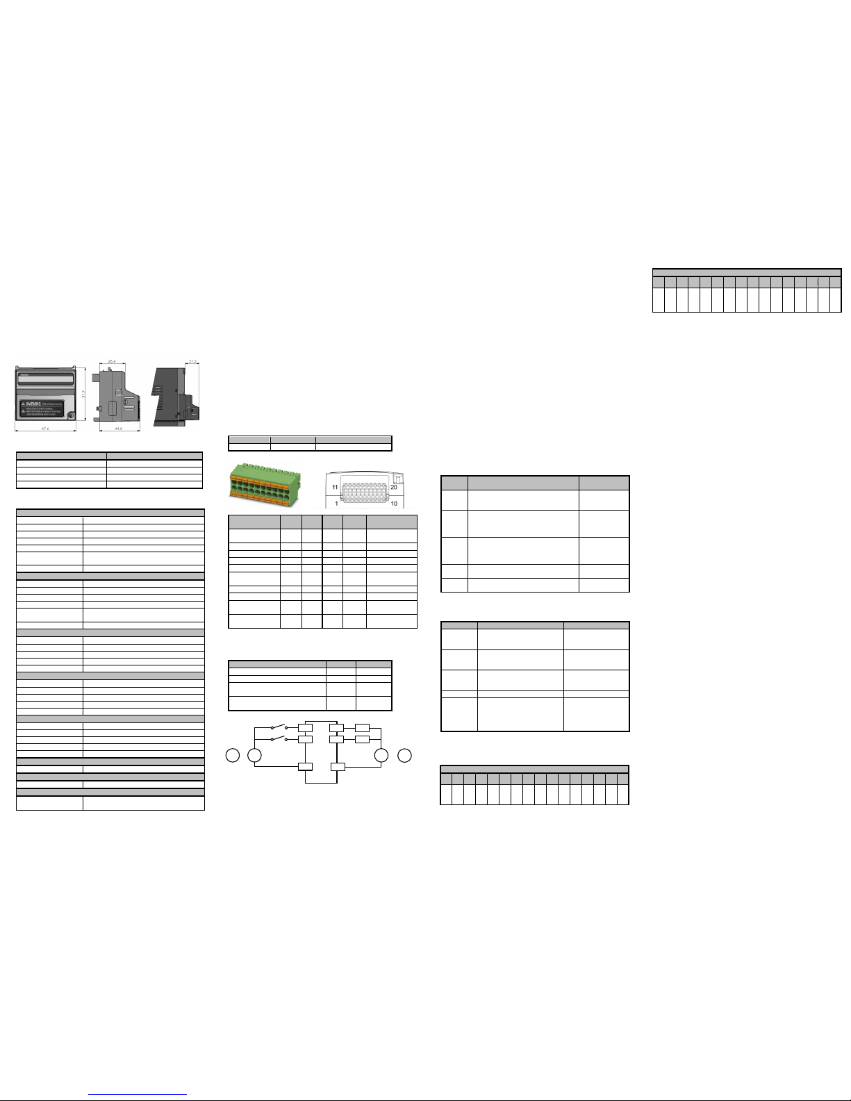
External Dimensions
External dimensions of the option board, shown in millimeters:
General Specifications
Item
Specifications
Ambient operating temperature
See MX2 series User’s manual.
Ambient operating humidity
See MX2 series User’s manual.
Storage temperature
-20 ºC to 65 ºC
Weight
170g
Detailed Input / Output Specifications
Discrete Logic Inputs (DI)
No. of inputs
8
ON voltage
18 VDC minimum
OFF voltage
3 VDC maximum
Allowable voltage
27 VDC maximum
Load current at 24VDC
5 mA
Input type
sink or source (selectable by connecting CMI
either to – or + terminal of the 24V IO supply)
Common
CMI
Discrete Logic Outputs (DO)
No. of outputs
4
ON state current
50 mA maximum
ON state voltage drop
3 VDC maximum
OFF state voltage
27 VDC maximum
Output type
sink or source (selectable by connecting CMO
either to – or + terminal of the 24V IO supply)
Common
CMO
Analog Voltage Input (AIV)
Range
-10 to 10 VDC
Input impedance
10 kOhms
Accuracy
1% of FS
Resolution
12 bit
Common
CMA
Analog Current Input (AIC)
Range
0 to 20 mA
Input impedance
100 Ohms
Accuracy
1.5% of FS
Resolution
12 bit
Common
CMA
Analog Voltage Output (AO)
Range
0 to 10 VDC
Output current
10 mA maximum
Accuracy
1% of FS
Resolution
12 bit
Common
CMA
Common for Analog Inputs and Output (CMA)
Maximum current
50 mA (sum of analog input/output currents)
Common for Discrete Logic Inputs (CMI)
Maximum current
50 mA (sum of discrete logic input currents)
Common for Discrete Logic Outputs (CMO)
Maximum current
200 mA (sum of discrete logic output
currents)
Installation Procedure
Follow the next steps to install a 3G3AX-MX2-EIO15-E on an MX2-A□
series inverter:
1. Power down the inverter
2. Loosen the screw of the option board cover on the inverter, remove
the cover and put the cover aside.
3. For inverters up to 4.0 kW only: loosen the screws of the terminal
block cover and remove the cover to enable access to the chassis
ground terminal screws.
4. Connect the grounding cable to the chassis ground of the inverter
(located on the cooling fin) and the IO connector Functional Ground
(FG) pins 1 and/or 11.
5. If removed, mount the terminal cover again and tighten the screw(s)
6. Push the 3G3AX-MX2-EIO15-E option board into the previous
location of the option board cover until it clicks into place
7. Tighten the screw of the option board (do not over-tighten).
8. Select the right warning language from the warning label sheet and
replace the English warning if appropriate.
Please note the RS485 MODBUS RTU Port (pin SP, SN) of the inverter is
not supported when the 3G3AX-MX2-EIO15-E is mounted.
IO Connector and Wiring
The 3G3AX-MX2-EIO15-E option board is supplied with a double-row
20pins connector plug for the IO wiring and a grounding cable.
Part
Manufacturer
Type
Connector
Phoenix
DFMC 1.5/10 – ST – 3.5
Wire the connector following the below pin layout:
Description
Item
Pin
No.
Pin
No.
Item
Description
Functional
Ground
FG 1 11
FG
Functional
Ground
Digital Input 4
DI4 2 12
DI0
Digital Input 0
Digital Input 5
DI5 3 13
DI1
Digital Input 1
Digital Input 6
DI6 4 14
DI2
Digital Input 2
Digital Input 7
DI7 5 15
DI3
Digital Input 3
Digital Output
Common
CMO 6 16
CMI
Digital Input
Common
Digital Output 2
DO2 7 17
DO0
Digital Output 0
Digital Output 3
DO3 8 18
DO1
Digital Output 1
Analog
Common
CMA 9 19
AO
Analog Voltage
Output
Analog
Current Input
AIC
10
20
AIV
Analog Voltage
Input
Use shielded cable for the wiring of the inputs/outputs. Connect the
cable shield to ground.
Keep the wiring for the option board separated from the inverter
power wiring and the inverter motor wiring.
Conductor cross section
Min
Max
Solid wire
0.2mm2
1.5mm2
Stranded wire
0.2mm2
1.5mm2
Stranded wire, with ferrule without
plastic sleeve
0.25mm2
1.5mm2
Stranded wire, with ferrule with
plastic sleeve
0.25mm2
0.75mm2
Wire the 3G3AX-MX2-EIO15-E according to the wiring example below.
DI..
CMI
DI0
24 V
+
-
DO..
DO0
CMO
Load
Load
24 V
or
-
+
or
+
+
-
Configuration Instructions
1. Power up the inverter and perform the inverter’s restore factory
default settings setting parameters b084 and b180 (see MX2 series
User’s Manual).
2. Select the correct Filter parameter values in case default is not
acceptable:
Analog Input AIV Filter Time using P160
Analog Input AIC Filter Time using P161
Digital Inputs DI Filter Time using P162
3. Be sure to set parameter A017 to zero to stop the Drive Programs
and data exchange of the 3G3AX-MX2-EIO15-E*. Use either the
Drive Program control buttons in CX-Drive or the MX2 Digital
Operator to change the A017 value.
4. Create your program with CX-Drive’s Drive Programming tool using
the dedicated user parameters for your application purpose and
download to the inverter.
5. Set the inverter parameter A017 to value 1 or 2 to start the Drive
Programming program.
6. In case of a parameter change in step 2, power cycle the inverter.
7. The option board runs automatically.
* The 3G3AX-MX2-EIO15-E will only refresh the IO status when the Drive
Program is running. Be sure to have the IO in a failsafe state before
downloading the program or stopping the Drive Program. The outputs will
keep their latest values.
Option Board Inverter Parameters Details
I/O Data
Use the following parameters within the Drive Program to control the
inputs and outputs of the 3G3AX-MX2-EIO15-E.
Param
eter
Description
Range
(decimal)
U(00)
The 8 digital input data of the Unit.
0 to 255
[from bit 0 (DI0)
to bit 7 (DI7)]
U(01)
The 4 digital output data of the Unit.
0 to 15
[from bit 0
(DO0) to bit 3
(DO3)]
U(02)
The Analog Voltage Input AIV value of
the Unit.
Note this value is unsigned. Use
UL(00) as in programming example.
-10000 to 10000
[-10 to 10 VDC]
U(03)
The Analog Current Input AIC value of
the Unit.
0 to 10000
[0 to 20 mA]
U(04)
The Analog Voltage Output AO value
of the Unit.
0 to 10000
[0 to 10 VDC]
Parameter settings
Please note a change of value for these parameters (except P165)
requires a power cycle of the inverter and the 3G3AX-MX2-EIO15-E.
Parameter
Description
Range
P160
Analog Input AIV Filter Time
0 to 255,
[ 1 to 255: x2ms filter
0: default 16ms]
P161
Analog Input AIC Filter Time
0 to 255,
[ 1 to 255: x2ms filter
0: default 16ms]
P162
Digital Input DI Filter Time
0 to 255,
[ 1 to 255: x2ms filter
0: default 16ms]
P163, P164
Reserved (do not write)
P165
The Option board status *
Bit 00:
Running [ 0 = Not running,
1 = Running ]
Other bits are reserved.
0 to 1
* Be sure to check that the Running bit is 1 before using the input data.
Dedicated User Parameters U(00) and U(01) bit detail description
U(00): Stores the status of the Unit’s 8 Digital Inputs DI0 to DI7.
U(00) Bits
15
14
13
12
11
10 9 8 7 6 5 4 3 2 1 0
* * * * * * *
*
DI7
DI6
DI5
DI4
DI3
DI2
DI1
DI0
* Bits 08 to 15 are reserved for future use. Please do not use.
U(01): Writes the Unit’s 4 Digital Outputs DO0 to DO3.
U(01) Bits
15
14
13
12
11
10 9 8 7 6 5 4 3 2 1 0
* * * * * * * * * * *
*
DO3
DO2
DO1
DO0
* Bits 04 to 15 are reserved for future use. Please keep to zero.
Drive Programming Example
'**********************************************
'**3G3AX-MX2-EIO15-E Programming Example **
'**********************************************
#alias global DI as U(00) '8 Digital Inputs
#alias global DO as U(01) '4 Digital Outputs
#alias global uAIV as U(02) 'AIV (unsigned)
#alias global AIC as U(03) 'AIC
#alias global AO as U(04) 'AO
#alias global obstatus as P165 'Option board status
#alias global AIV as UL(00) 'AIV (signed)
#alias global neg0 as U(20) 'AIV negative
#alias global DIOtemp as U(21)'Temp DIO
#alias global running as U(22) 'Running status
#alias global DI0 as U(11)
#alias global DI1 as U(12)
#alias global DI2 as U(13)
#alias global DI3 as U(14)
#alias global DI4 as U(15)
#alias global DI5 as U(16)
#alias global DI6 as U(17)
#alias global DI7 as U(18)
#alias global cDI0 as 1 'Constant definition DI0
#alias global cDI1 as 2 'Constant definition DI1
#alias global cDI2 as 4 'Constant definition DI2
#alias global cDI3 as 8 'Constant definition DI3
#alias global cDI4 as 16 'Constant definition DI4
#alias global cDI5 as 32 'Constant definition DI5
#alias global cDI6 as 64 'Constant definition DI6
#alias global cDI7 as 128 'Constant definition DI7
#alias global cDO0 as 1 'Constant definition DO0
#alias global cDO1 as 2 'Constant definition DO1
#alias global cDO2 as 4 'Constant definition DO2
#alias global cDO3 as 8 'Constant definition DO3
entry
obstatus := 0 'Write zero to P165
DO := 0 'Set Dig Outputs to zero
AO := 0 'Set Analog Output to zero
:ini_
running := obstatus
running := running mod 2
if running = 1 goto loop_
goto ini_
:loop_
'* Include user code here (see examples below)
'* Set Digital output 0
DO := DO or cDO0
'* Reset Digital output 1
DIOtemp := not cDO1
DO := DO and DIOtemp
'* Read Digital input 0 into DI0
DIOtemp := DI and cDI0
DI0 := DIOtemp / cDI0
'* Read Digital input 1 into DI1
DIOtemp := DI and cDI1
DI1 := DIOtemp / cDI1
'* Convert Analog input 0 value to UL(00) signed
neg0 := uAIV and 32768
if neg0 > 1 then
AIV := uAIV - 65536
else
AIV := uAIV
endif
goto loop_
end
 Loading...