

Page 1

At the end of this document you will find links to products related to this catalog. You can go directly to our shop by
clicking HERE. HERE
Page 2

Inverter
MX2 Series
EtherCAT Communication Unit
User’s Manual
I574-E1-02
3G3AX-MX2-ECT
EtherCAT Communication Unit
Page 3

© OMRON, 2011
All rights reserved. No part of this publication may be reproduced, stored in a retrieval system, or transmitted, in any
form, or by any means, mechanical, electronic, photocopying, recording, or otherwise, without the prior written permission of OMRON.
No patent liability is assumed with respect to the use of the information contained herein. Moreover, because OMRON is
constantly striving to improve its high-quality products, the information contained in this manual is subject to change
without notice. Every precaution has been taken in the preparation of this manual. Nevertheless, OMRON assumes no
responsibility for errors or omissions. Neither is any liability assumed for damages resulting from the use of the information contained in this publication.
Page 4

1
Introduction
EtherCAT Communication Unit USER’S MANUAL (3G3AX-MX2-ECT)
Introduction
Thank you for choosing the EtherCAT Communication Unit 3G3AX-MX2-ECT. This User's Manual
(hereinafter called this manual) describes the parameter setting methods required for installation/wiring
and operation of the 3G3AX-MX2-ECT, as well as troubleshooting and inspection methods.
This manual should be delivered to the actual end user of the product.
After reading this manual, keep it handy for future reference.
This manual describes the specifications and functions of the product as well as the relations between
them. You should assume that anything not described in this manual is not possible with the product.
This manual is intended for those with knowledge of the workings of electricity (qualified electric
engineers or the equivalent), and also in charge of:
• Introducing the control equipment
• Designing the control system
• Installing and/or connecting the control equipment
• Field management
Intended Readers
Page 5

Read and Understand this Manual
2
EtherCAT Communication Unit USER’S MANUAL (3G3AX-MX2-ECT)
Read and Understand this Manual
Please read and understand this manual before using the product. Please consult your OMRON
representative if you have any questions or comments.
Warranty and Limitations of Liability
WARRANTY
OMRON's exclusive warranty is that the products are free from defects in materials and workmanship for a period
of one year (or other period if specified) from date of sale by OMRON.
OMRON MAKES NO WARRANTY OR REPRESENTATION, EXPRESS OR IMPLIED, REGARDING
NON-INFRINGEMENT, MERCHANTABILITY, OR FITNESS FOR PARTICULAR PURPOSE OF THE
PRODUCTS. ANY BUYER OR USER ACKNOWLEDGES THAT THE BUYER OR USER ALONE HAS
DETERMINED THAT THE PRODUCTS WILL SUITABLY MEET THE REQUIREMENTS OF THEIR INTENDED
USE. OMRON DISCLAIMS ALL OTHER WARRANTIES, EXPRESS OR IMPLIED.
LIMITATIONS OF LIABILITY
OMRON SHALL NOT BE RESPONSIBLE FOR SPECIAL, INDIRECT, OR CONSEQUENTIAL DAMAGES, LOSS
OF PROFITS OR COMMERCIAL LOSS IN ANY WAY CONNECTED WITH THE PRODUCTS, WHETHER
SUCH CLAIM IS BASED ON CONTRACT, WARRANTY, NEGLIGENCE, OR STRICT LIABILITY.
In no event shall the responsibility of OMRON for any act exceed the individual price of the product on which
liability is asserted.
IN NO EVENT SHALL OMRON BE RESPONSIBLE FOR WARRANTY, REPAIR, OR OTHER CLAIMS
REGARDING THE PRODUCTS UNLESS OMRON'S ANALYSIS CONFIRMS THAT THE PRODUCTS WERE
PROPERLY HANDLED, STORED, INSTALLED, AND MAINTAINED AND NOT SUBJECT TO CONTAMINATION,
ABUSE, MISUSE, OR INAPPROPRIATE MODIFICATION OR REPAIR.
Page 6

3
Read and Understand this Manual
EtherCAT Communication Unit USER’S MANUAL (3G3AX-MX2-ECT)
Application Considerations
SUITABILITY FOR USE
OMRON shall not be responsible for conformity with any standards, codes, or regulations that apply to the
combination of products in the customer's application or use of the products.
At the customer's request, OMRON will provide applicable third party certification documents identifying ratings
and limitations of use that apply to the products. This information by itself is not sufficient for a complete
determination of the suitability of the products in combination with the end product, machine, system, or other
application or use.
The following are some examples of applications for which particular attention must be given. This is not intended
to be an exhaustive list of all possible uses of the products, nor is it intended to imply that the uses listed may be
suitable for the products:
Outdoor use, uses involving potential chemical contamination or electrical interference, or conditions or uses
not described in this manual.
Nuclear energy control systems, combustion systems, railroad systems, aviation systems, medical equipment,
amusement machines, vehicles, safety equipment, and installations subject to separate industry or government
regulations.
Systems, machines, and equipment that could present a risk to life or property.
Please know and observe all prohibitions of use applicable to the products.
NEVER USE THE PRODUCTS FOR AN APPLICATION INVOLVING SERIOUS RISK TO LIFE OR PROPERTY
WITHOUT ENSURING THAT THE SYSTEM AS A WHOLE HAS BEEN DESIGNED TO ADDRESS THE RISKS,
AND THAT THE OMRON PRODUCTS ARE PROPERLY RATED AND INSTALLED FOR THE INTENDED USE
WITHIN THE OVERALL EQUIPMENT OR SYSTEM.
PROGRAMMABLE PRODUCTS
OMRON shall not be responsible for the user's programming of a programmable product, or any consequence
thereof.
Disclaimers
CHANGE IN SPECIFICATIONS
Product specifications and accessories may be changed at any time based on improvements and other reasons.
It is our practice to change model numbers when published ratings or features are changed, or when significant
construction changes are made. However, some specifications of the products may be changed without any
notice. When in doubt, special model numbers may be assigned to fix or establish key specifications for your
application on your request. Please consult with your OMRON representative at any time to confirm actual
specifications of purchased products.
DIMENSIONS AND WEIGHTS
Dimensions and weights are nominal and are not to be used for manufacturing purposes, even when tolerances
are shown.
PERFORMANCE DATA
Performance data given in this manual is provided as a guide for the user in determining suitability and does not
constitute a warranty. It may represent the result of OMRON's test conditions, and the users must correlate it to
actual application requirements. Actual performance is subject to the OMRON Warranty and Limitations of
Liability.
ERRORS AND OMISSIONS
The information in this manual has been carefully checked and is believed to be accurate; however, no
responsibility is assumed for clerical, typographical, or proofreading errors, or omissions.
Page 7
Safety Precautions
4
EtherCAT Communication Unit USER’S MANUAL (3G3AX-MX2-ECT)
Safety Precautions
In this manual, the following precautions and signal words are used to provide information to ensure the
safe use of the EtherCAT Communication Unit 3G3AX-MX2-ECT.
The information provided here is vital to safety. Strictly observe the precautions provided.
The precautions and symbols are as follows.
Precautions for Safe Use
Indicates precautions on what to do and what not to do to ensure using the product safely.
Precautions for Correct Use
Indicates precautions on what to do and what not to do to ensure that the product does not
become inoperative, malfunction, or disrupt functionality and performance.
Additional Information
Additional information to increase understanding or make operation easier.
Indications and Meanings of Safety Information
Meanings of Signal Words
Indicates a potentially hazardous situation which, if not avoided, may result in
minor or moderate injury, or may result in serious injury or death. Additionally
there may be significant property damage.
Indicates a potentially hazardous situation which, if not avoided, may result in
minor or moderate injury, or in property damage.
WARNING
Caution
Page 8
5
Safety Precautions
EtherCAT Communication Unit USER’S MANUAL (3G3AX-MX2-ECT)
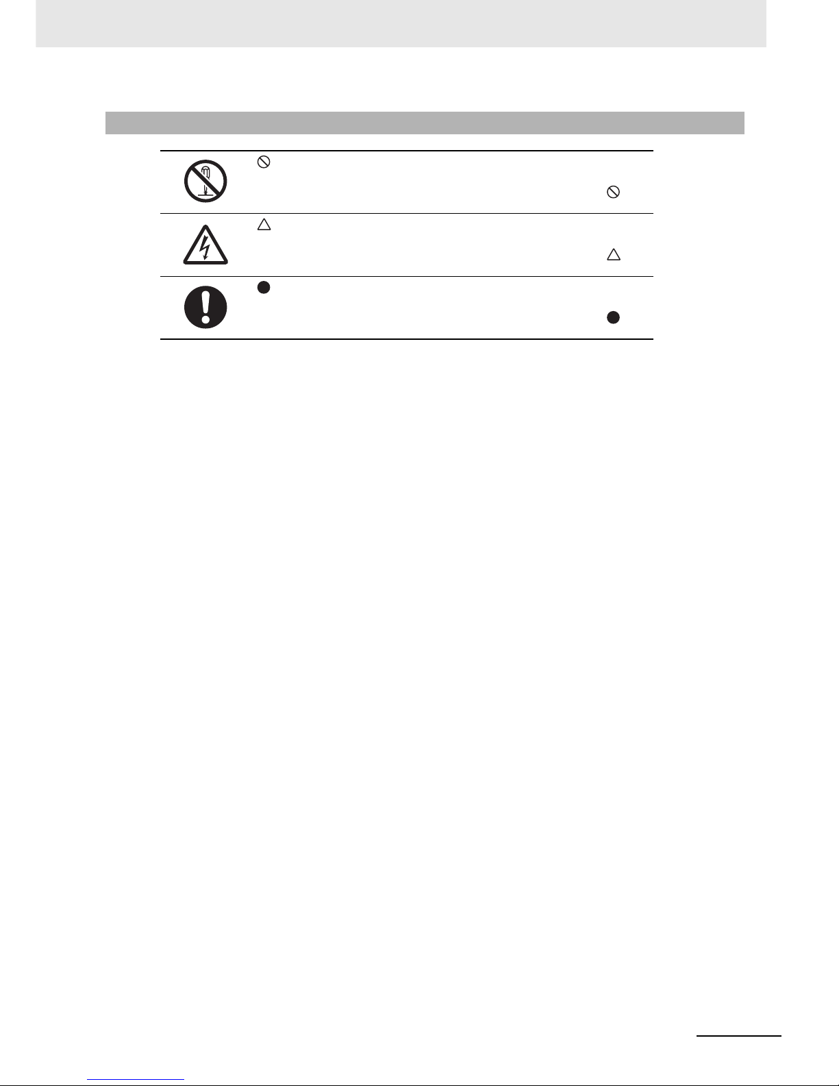
Example of Symbols
This symbol indicates a prohibited item (an item you must not do).
The specific instruction is indicated using an illustration or text inside or near .
The symbol shown to the left indicates "disassembly prohibited".
This symbol indicates danger and caution.
The specific instruction is indicated using an illustration or text inside or near .
The symbol shown to the left indicates "beware of electric shock".
This symbol indicates a compulsory item (an item that must be done).
The specific instruction is indicated using an illustration or text inside or near .
The symbol shown to the left indicates "typical compulsory items".
Page 9
Safety Precautions
6
EtherCAT Communication Unit USER’S MANUAL (3G3AX-MX2-ECT)
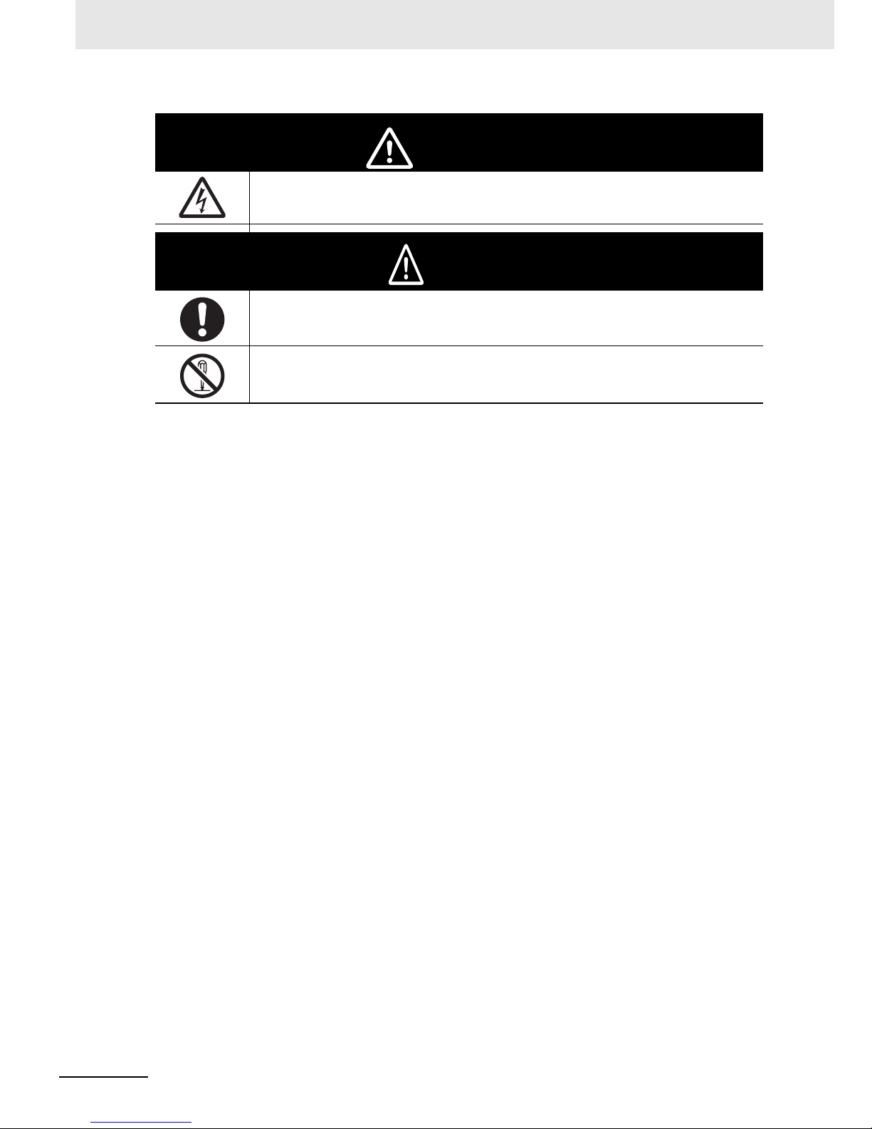
Do not remove the terminal block cover or the EtherCAT Communication Unit while the power is being
supplied, and within 10 minutes after the power is turned off.
The inverter has high voltage parts inside which, if short-circuited, might cause damage to itself or other
property. Place covers on the openings or take other precautions to make sure that no metal objects such
as cutting bits or lead wire scraps go inside when installing and wiring.
Do not disassemble, repair, or modify the inverter. Failure to follow this guideline may result in injury.
WARNING
Caution
Page 10

7
Precautions for Safe Use
EtherCAT Communication Unit USER’S MANUAL (3G3AX-MX2-ECT)
Precautions for Safe Use
Do not store or use the product in the following places.
• Locations subject to direct sunlight.
• Locations subject to ambient temperature exceeding the specifications.
• Locations subject to relative humidity exceeding the specifications.
• Locations subject to condensation due to severe temperature fluctuations.
• Locations subject to corrosive or flammable gases.
• Locations subject to exposure to combustibles.
• Locations subject to dust (especially iron dust) or salts.
• Locations subject to exposure to water, oil, or chemicals.
• Locations subject to direct vibration or shock.
• Do not drop or apply strong impact on the product. Doing so may result in damaged parts or
malfunction.
• If you are transporting the product installed to the inverter, be sure to carry it by holding an inverter
radiation fin.
• Do not remove the cover of the EtherCAT Communication Unit. Also, make sure that the unit
fastening screws are tightened to the specified torque.
• Install a stop motion device to ensure safety. In particular, when it is set to continue operation when a
communications error occurs, the inverter may not stop and damage to the equipment.
• Take sufficient shielding measures when using the product in the following locations. Not doing so
may result in damage to the product.
Locations subject to static electricity or other forms of noise.
Locations subject to strong magnetic fields.
Locations close to power lines.
• Be sure to confirm the permissible range of motors and machines before operation because the
inverter speed can be changed easily from low to high.
• Be sure to confirm safety before conducting maintenance, inspection or parts replacement.
Installation and Storage
Transportation, Installation, and Wiring
Operation and Adjustment
Maintenance and Inspection
Page 11
Precautions for Correct Use
8
EtherCAT Communication Unit USER’S MANUAL (3G3AX-MX2-ECT)
Precautions for Correct Use
Follow the inverter mounting direction restrictions.
If this EtherCAT Communication Unit is installed, the inverter Modbus-RTU communication becomes
disabled.
Comply with the local ordinance and regulations when disposing of the product.
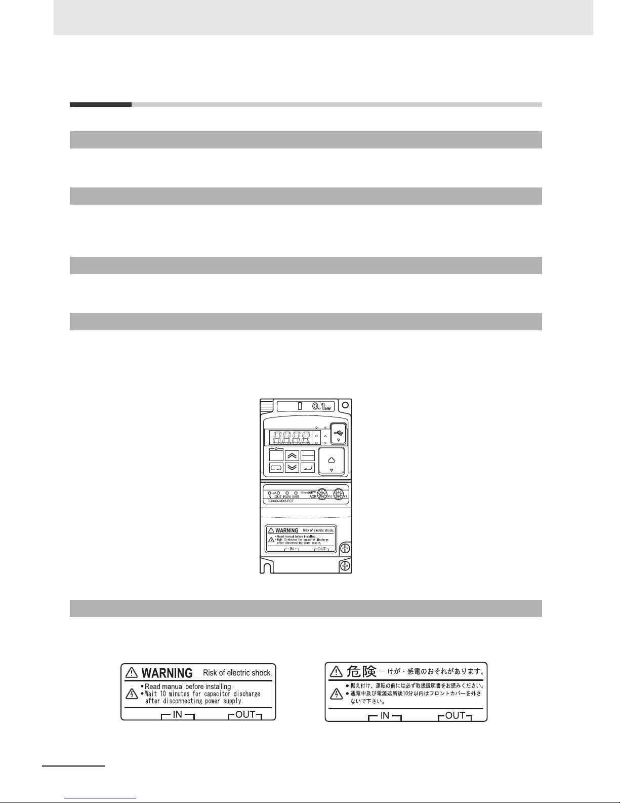
• After installing this EtherCAT Communication Unit to the inverter, warning labels are pasted on the
product as shown in the following illustration.
• Be sure to follow the instructions.
(Notes) The overall appearance varies depending on the inverter capacity.
The warning description is written in English when it is shipped from the factory.
Affix the Japanese warning label included with the product if necessary.
Installation
Modbus-RTU communication
Product Disposal
Warning Label Location
Warning Description
STOP
RESET
RUN
Hz
A
ALM
PRG
3G3MX2
INVERTER
RUN
PWR
SYSDRIVE
200V
3PHASE
Page 12

9
Precautions for Correct Use
EtherCAT Communication Unit USER’S MANUAL (3G3AX-MX2-ECT)
This EtherCAT Communication Unit can be used with the inverter of unit version 1.1 or higher.
Make sure that the unit version of the inverter is 1.1 or higher.
The unit version of the inverter can be checked on the nameplate of the inverter.
(The unit version can not be checked on the CX-Drive.)
Inverter Version
Page 13

Applicable Standards
10
EtherCAT Communication Unit USER’S MANUAL (3G3AX-MX2-ECT)
Applicable Standards
(Notes) To conform to EMC Directives, the product must be installed under the conditions described in "2-5-3
Wiring Conforming to EMC Directives".
When the EtherCAT Communication Unit is mounted on the inverter unit, inverter’s conformance to the
Machinery Directive becomes invalid.
This product is conformance tested.
EC Directives
EC Directives Applicable Standard
EMC Directive EN61800-3
Low Voltage Directive EN61800-5-1
UL/cUL Standards
Standards Applicable Standard
UL/cUL UL508c
Functional Safety
EtherCAT Conformance Test
Page 14

11
Trademarks
EtherCAT Communication Unit USER’S MANUAL (3G3AX-MX2-ECT)
Trademarks
• EtherCAT is a registered trademark of Beckhoff Automation GmbH (Germany). EtherCAT technology
is protected by patents.
EtherCAT
is a registered trademark and patented technology, licensed by Beckhoff Automation
GmbH, Germany.
• Windows, Windows 98, Windows XP, Windows Vista and Windows 7 are registered trademarks of
Microsoft Corporation in the USA and other countries.
• Sysmac is a FA product of OMRON and a trademark or registered trademark of OMRON in Japan
and other countries.
• CX-One is a registered trademark of OMRON's FA Integrated Tool Package.
• Other system names and product names that appear in this manual are the trademarks or registered
trademarks of the relevant companies.
Page 15

Checking Before Unpacking
12
EtherCAT Communication Unit USER’S MANUAL (3G3AX-MX2-ECT)
Checking Before Unpacking
On delivery, be sure to check that the delivered product is the EtherCAT Communication Unit
3G3AX-MX2-ECT model that you ordered. Should you find any problems with the product, immediately
contact your nearest local sales representative or OMRON sales office.
The nameplate is affixed to the back side of the product.
Note that the Instruction manual and the Japanese warning label accessories are included with the
EtherCAT Communication Unit 3G3AX-MX2-ECT.
Checking the Product
Checking the Nameplate
Checking the Model
Checking the Accessories
****** ********
3G3AX-MX2-ECT
EtherCAT Communications Unit
For 3G3MX2 series only
Page 16
13
Revision History
EtherCAT Communication Unit USER’S MANUAL (3G3AX-MX2-ECT)
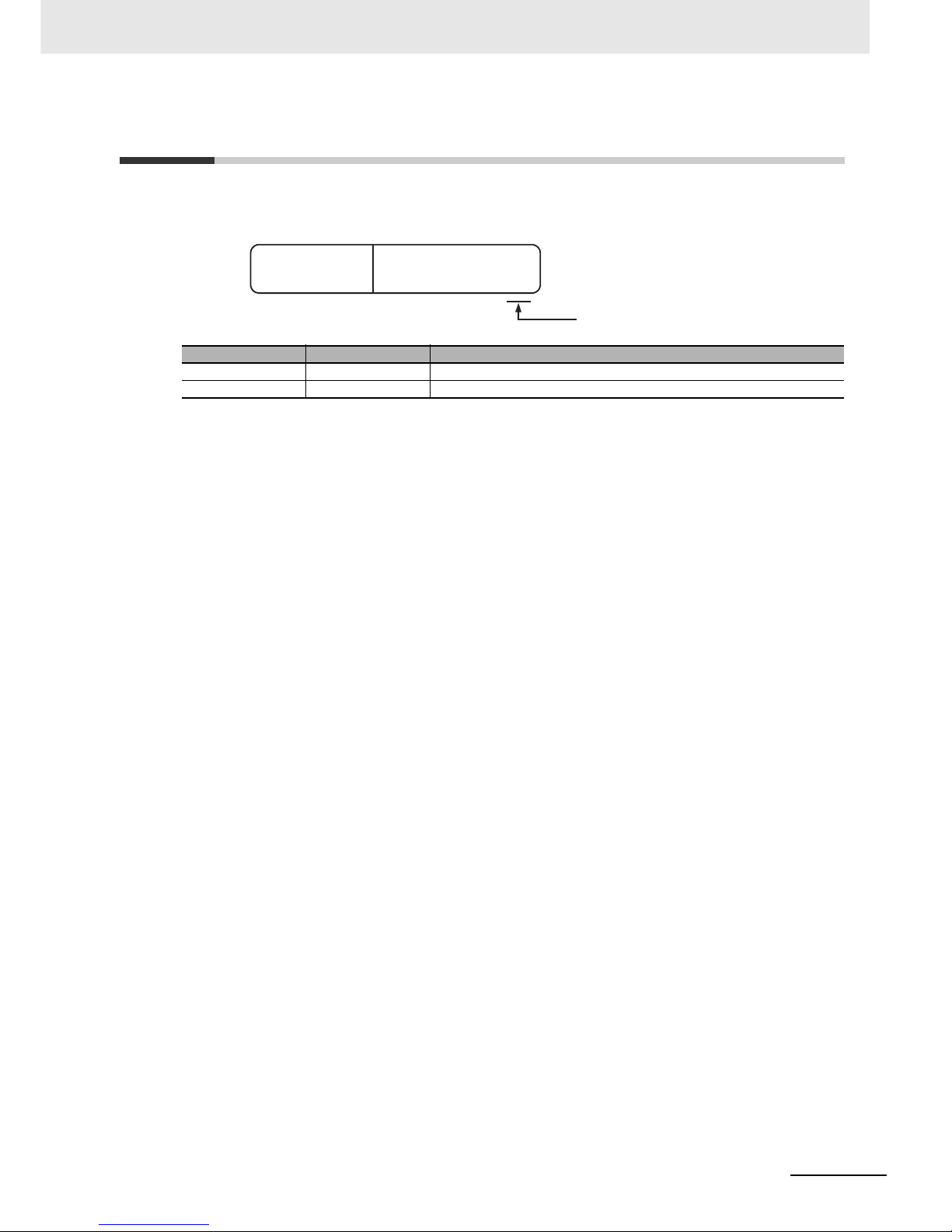
Revision History
A manual revision code appears as a suffix to the catalog number located at the top left of the front and
lower right of the back covers.
Revision code Revision date Changes and revision pages
01 August 2010 First printing
02 July 2011 Added information on Machine Automation Controller NJ501-1x00 series.
Man.No. I574-E1-02
Revised symbols
Page 17

Related Manuals
14
EtherCAT Communication Unit USER’S MANUAL (3G3AX-MX2-ECT)
Related Manuals
When operating this product, it is necessary to have information about the device you are connecting.
Please see the manuals below for related product information.
Manual number
Multi-function Compact Inverter SYSDRIVE MX2 SERIES USER’S MANUAL I570
Model/Name
* Refer to the user’s manual of the Inverter for information on Inverter operation.
Manual number
Position Control Units CJ1W-NC281/NC481/NC881/NCF81/NC482/NC882 OPERATION MANUAL
W487
EtherCAT Master manual
Model/Name
* When using the Master Unit other than as specified above, refer to the manual (operation manual) for that Master
Unit.
W501
NJ-series CPU Unit Software User's Manual
Page 18

15
About This Manual
EtherCAT Communication Unit USER’S MANUAL (3G3AX-MX2-ECT)
About This Manual
This User's Manual consists of chapters listed below.
Understanding the following configuration ensures more effective use of the product.
Overview
Chapter 1
EtherCAT Network
This chapter explains the overview, features and specifications of the
EtherCAT Communication Unit.
Chapter 2
Starting a Sample System
This chapter explains information such as the mounting, wiring and
setting methods for the EtherCAT Communication Unit.
Chapter 3
Common Slave Specifications
This chapter explains the common slave specifications during EtherCAT
communication, and about the ESIs, PDOs and SDOs.
Chapter 4 Inverter Control This chapter describes the profiles that are used to control inverters.
Chapter 5 CiA402 Drive Profile This chapter explains about the CiA402 drive profile.
Chapter 6 Handling of Errors and
Maintenance
This chapter explains how to handle any errors that occur in the
EtherCAT Communication Unit.
Appendix The appendix provides a list of objects.
Page 19

16
EtherCAT Communication Unit USER’S MANUAL (3G3AX-MX2-ECT)
CONTENTS
CONTENTS
Introduction ...............................................................................................................1
Read and Understand this Manual ..........................................................................2
Safety Precautions.................................................................................................... 4
Precautions for Safe Use..........................................................................................7
Precautions for Correct Use.....................................................................................8
Applicable Standards..............................................................................................10
Trademarks ..............................................................................................................11
Checking Before Unpacking...................................................................................12
Revision History...................................................................................................... 13
Related Manuals...................................................................................................... 14
About This Manual ..................................................................................................15
Section 1 EtherCAT Network
1-1 Overview of the EtherCAT Communication Unit................................................................... 1-2
1-1-1 Features of the EtherCAT Communication Unit ..........................................................................1-2
1-2 Overview of EtherCAT ............................................................................................................. 1-3
1-2-1 Features of EtherCAT..................................................................................................................1-3
1-2-2 EtherCAT System........................................................................................................................1-4
1-2-3 EtherCAT Communication Types ................................................................................................1-5
1-3 EtherCAT System Configuration ............................................................................................ 1-6
1-3-1 System Configuration..................................................................................................................1-6
1-3-2 Overview of Component Equipment ...........................................................................................1-7
Section 2 Starting a Sample System
2-1 Part Names and Settings for the EtherCAT Communication Unit....................................... 2-2
2-1-1 Part Names .................................................................................................................................2-2
2-1-2 Status Indicator Names...............................................................................................................2-3
2-1-3 Rotary Switches for Node Address Setting.................................................................................2-4
2-1-4 Communications Connector........................................................................................................2-5
2-1-5 Recommended Products.............................................................................................................2-6
2-1-6 Connection between Communications Cables and Connectors .................................................2-7
2-2 Basic Usage Procedures and Configuration Example......................................................... 2-8
2-2-1 Basic Usage Procedures............................................................................................................. 2-8
2-2-2 System Configuration Example...................................................................................................2-9
2-3 CJ1W-NCx82 Master Setting................................................................................................. 2-11
2-3-1 Mounting the CJ1W-NCx82 ......................................................................................................2-11
2-3-2 CJ1W-NCx82 Setting................................................................................................................ 2-11
2-4 NJ501-1x00 Master Setting ................................................................................................... 2-12
2-4-1 Mounting the NJ501-1x00.........................................................................................................2-12
2-4-2 NJ501-1x00 Setting...................................................................................................................2-12
Page 20

17
EtherCAT Communication Unit USER’S MANUAL (3G3AX-MX2-ECT)
CONTENTS
2-5 Mounting and Wiring for the EtherCAT Communication Unit ........................................... 2-13
2-5-1 Mounting the EtherCAT Communication Unit ........................................................................... 2-13
2-5-2 Wiring the EtherCAT Communication Unit................................................................................ 2-15
2-5-3 Wiring Conforming to EMC Directives ...................................................................................... 2-17
2-5-4 Node Address Settings for the EtherCAT Communication Unit................................................ 2-18
2-6 SYSDRIVE MX2 Series Settings ........................................................................................... 2-19
2-6-1 RUN Command Setting ............................................................................................................ 2-19
2-6-2 Frequency Reference Setting ................................................................................................... 2-19
2-6-3 Reset Selection Setting ............................................................................................................ 2-19
2-7 Communication Starting and Operation Checking with CJ1W-NCx82 Master ................ 2-20
2-7-1 Starting the System .................................................................................................................. 2-20
2-7-2 Network Setup .......................................................................................................................... 2-20
2-7-3 Checking the Master Unit ......................................................................................................... 2-20
2-7-4 Checking the Inverter and EtherCAT Communication Unit ....................................................... 2-21
2-7-5 Checking the Operation............................................................................................................ 2-21
2-8 Communication Starting and Operation Checking with NJ501-1x00 Master................... 2-22
2-8-1 Starting the System .................................................................................................................. 2-22
2-8-2 Network Setup .......................................................................................................................... 2-22
2-8-3 Checking the NJ501-1x00 Master ............................................................................................ 2-26
2-8-4 Checking the Inverter and EtherCAT Communication Unit ....................................................... 2-26
2-8-5 Checking the Operation............................................................................................................ 2-26
Section 3 Common Slave Specifications
3-1 Structure of CANopen over EtherCAT ................................................................................... 3-2
3-2 Communications Status Transitions ..................................................................................... 3-3
3-3 Process Data Objects (PDO)...................................................................................................3-4
3-3-1 Outline ........................................................................................................................................ 3-4
3-3-2 PDO Mapping Settings ............................................................................................................... 3-4
3-3-3 Sync Manager PDO Assignment Settings.................................................................................. 3-5
3-3-4 Fixed PDO Mapping ................................................................................................................... 3-5
3-4 Service Data Objects (SDO).................................................................................................... 3-6
3-4-1 Outline ........................................................................................................................................ 3-6
3-4-2 Abort Codes................................................................................................................................ 3-6
3-5 Emergency Messages ............................................................................................................. 3-7
3-5-1 Outline ........................................................................................................................................ 3-7
3-5-2 Error Code List............................................................................................................................ 3-7
3-6 Sysmac Device Functions ......................................................................................................3-8
Section 4 Inverter Control
4-1 Outline ...................................................................................................................................... 4-2
4-1-1 Function Selection ...................................................................................................................... 4-2
4-1-2 Object Mapping........................................................................................................................... 4-2
4-2 Control with the Position Control Unit................................................................................... 4-4
4-2-1 Inverter Setting ........................................................................................................................... 4-4
4-2-2 Object Mapping........................................................................................................................... 4-4
4-2-3 Control Method ........................................................................................................................... 4-5
4-2-4 Sample Program......................................................................................................................... 4-7
4-3 Control with the Independent Profile................................................................................... 4-10
4-3-1 Inverter Setting ......................................................................................................................... 4-10
4-3-2 Profile Allocation....................................................................................................................... 4-10
4-3-3 Control Method ......................................................................................................................... 4-10
4-4 Control with the CiA402 Profile ............................................................................................ 4-12
4-4-1 Inverter Setting ......................................................................................................................... 4-12
Page 21

18
EtherCAT Communication Unit USER’S MANUAL (3G3AX-MX2-ECT)
CONTENTS
4-4-2 Profile Allocation .......................................................................................................................4-12
4-4-3 Control Method..........................................................................................................................4-12
4-5 Control with the PDO Free Format....................................................................................... 4-14
4-5-1 Inverter Setting..........................................................................................................................4-14
4-5-2 Object Mapping .........................................................................................................................4-14
4-5-3 Objects Allocation in Sysmac Studio.........................................................................................4-15
4-5-4 Restrictions ...............................................................................................................................4-16
4-6 Trial operation via EtherCAT Communication Unit............................................................. 4-17
Section 5 CiA402 Drive Profile
5-1 Inverter State Control .............................................................................................................. 5-2
5-1-1 State Machine .............................................................................................................................5-2
5-1-2 State Descriptions.......................................................................................................................5-3
5-1-3 Command Coding .......................................................................................................................5-3
5-1-4 State Coding ...............................................................................................................................5-3
5-2 Modes of Operation................................................................................................................. 5-4
5-3 Velocity Mode........................................................................................................................... 5-5
5-4 Object Dictionary..................................................................................................................... 5-6
5-4-1 Object Dictionary Area ................................................................................................................5-6
5-4-2 Data Types..................................................................................................................................5-6
5-4-3 Object Description Format ..........................................................................................................5-6
5-5 CoE Communications Area .................................................................................................... 5-8
5-5-1 Communication Objects.............................................................................................................. 5-8
5-5-2 PDO Mapping Objects ..............................................................................................................5-11
5-5-3 Sync Manager Communication Objects.................................................................................... 5-13
5-6 Manufacturer Specific Area .................................................................................................. 5-16
5-6-1 Manufacturer Specific Objects ..................................................................................................5-16
5-6-2 Inverter Parameter Objects ....................................................................................................... 5-17
5-6-3 Independent Profile Objects......................................................................................................5-19
5-7 Device Profile area................................................................................................................. 5-22
5-7-1 Drive Profile Objects .................................................................................................................5-22
Section 6 Handling of Errors and Maintenance
6-1 Communication Line Errors ................................................................................................... 6-2
6-1-1 Status IndicatorExplanations and Error Handling .......................................................................6-2
6-1-2 Troubleshooting........................................................................................................................... 6-4
6-2 Message Errors........................................................................................................................ 6-5
6-3 Application Errors ................................................................................................................... 6-6
6-3-1 Error Statuses ............................................................................................................................. 6-6
6-3-2 Error Code List............................................................................................................................6-6
6-3-3 List of Cause Codes for PDO Mapping Errors ............................................................................ 6-7
6-3-4 AL Status Code List ....................................................................................................................6-9
6-4 Inverter Errors........................................................................................................................ 6-10
Appendices
A-1 Specifications ..........................................................................................................................A-2
A-1-1 Appearance and Dimensions......................................................................................................A-2
A-1-2 Common Specifications ..............................................................................................................A-2
A-1-3 EtherCAT Communications Specifications..................................................................................A-3
A-2 Communications Response Time ..........................................................................................A-4
Page 22

19
EtherCAT Communication Unit USER’S MANUAL (3G3AX-MX2-ECT)
CONTENTS
A-3 Object List ................................................................................................................................A-5
A-3-1 Object List...................................................................................................................................A-5
A-4 Inverter Parameter List............................................................................................................A-9
A-5 Sysmac Error Status Codes .................................................................................................A-36
A-5-1 Error Table ................................................................................................................................A-36
A-5-2 Error Descriptions..................................................................................................................... A-37
Index
Page 23

20
EtherCAT Communication Unit USER’S MANUAL (3G3AX-MX2-ECT)
CONTENTS
Page 24

1 - 1
1
EtherCAT Communication Unit USER’S MANUAL (3G3AX-MX2-ECT)
This chapter explains the overview and features of the EtherCAT Communication Unit
and the EtherCAT network.
1-1 Overview of the EtherCAT Communication Unit . . . . . . . . . . . . . . . . . . . . . 1-2
1-1-1 Features of the EtherCAT Communication Unit . . . . . . . . . . . . . . . . . . . . . . . . 1-2
1-2 Overview of EtherCAT . . . . . . . . . . . . . . . . . . . . . . . . . . . . . . . . . . . . . . . . . . 1-3
1-2-1 Features of EtherCAT . . . . . . . . . . . . . . . . . . . . . . . . . . . . . . . . . . . . . . . . . . . . 1-3
1-2-2 EtherCAT System . . . . . . . . . . . . . . . . . . . . . . . . . . . . . . . . . . . . . . . . . . . . . . . 1-4
1-2-3 EtherCAT Communication Types . . . . . . . . . . . . . . . . . . . . . . . . . . . . . . . . . . . 1-5
1-3 EtherCAT System Configuration . . . . . . . . . . . . . . . . . . . . . . . . . . . . . . . . . . 1-6
1-3-1 System Configuration . . . . . . . . . . . . . . . . . . . . . . . . . . . . . . . . . . . . . . . . . . . . 1-6
1-3-2 Overview of Component Equipment . . . . . . . . . . . . . . . . . . . . . . . . . . . . . . . . . 1-7
EtherCAT Network
Page 25

1 EtherCAT Network
1 - 2
EtherCAT Communication Unit USER’S MANUAL (3G3AX-MX2-ECT)
1-1 Overview of the EtherCAT
Communication Unit
The EtherCAT Communication Unit is an interface unit. When installed to a SYSDRIVE MX2-series
multi-function compact inverter, it provides support for 100-Mbps EtherCAT.
Support for EtherCAT enables operating and stopping with high-speed communication, monitoring the
operation status, and changing the various set values, and provides support for a wide range of
applications.
The EtherCAT Communication Unit has the features shown below.
As a Sysmac Device, you can use the MX2 Series EtherCAT Communication Unit together with the
NJ-series Machine Automation Controller and the Sysmac Studio Automation Software to achieve
optimum functionality and ease of operation.
* Sysmac Device is a generic term for OMRON control devices such as an EtherCAT Slave, designed with unified
communications specifications and user interface specifications.
When the CJ1W-NCx82 Master Unit, or Machine Automation Contoroller NJ501-1x00 series is used,
the basic control function, frequency setting function and output frequency monitor function are
assigned to the process data. This means that the inverter can be controlled as easily as normal I/O
control.
The Velocity mode of the CANopen drive profile (CiA402) enables common control that does not vary
with the manufacturer.
When a communication master that supports the process data mapping is used, user can assign the
inverter parameters to the process data.
This product can be used when the communication master is a Machine Automation Controller
NJ501-1x00 series.
EtherCAT supports connection with Servo Drives and digital I/O slaves,as well as Inverters,allowing
flexible network building.
1-1-1 Features of the EtherCAT Communication Unit
Optimal functionality and ease of operation by standardizing
specifications
Communication function as easy as I/O control
Supports the Velocity mode of CiA402
PDO free format
Using together with slaves
Page 26

1 - 3
1 EtherCAT Network
EtherCAT Communication Unit USER’S MANUAL (3G3AX-MX2-ECT)
1-2 Overview of EtherCAT
1
1-2-1 Features of EtherCAT
1-2 Overview of EtherCAT
Ethernet Control Automation Technology (EtherCAT) is a high-performance industrial network system
based on Ethernet system and can realize faster and more efficient communications.
Each node achieves a short cycle time by transmitting Ethernet frames at high speed.
In addition, even though EtherCAT has its own communication protocol, it uses standard Ethernet
technology in its physical layer. This provides a universal design feature because commercially
available Ethernet cables can be used. Its effectiveness can be fully utilized not only in large control
systems where high processing speed and system integration are required, but also in small to
medium-sized systems.
EtherCAT has the features shown below.
Ultra high-speed communication of 100 Mbps
The I/O response time from the generation of the input signal to the transmission of the output signal
is greatly reduced. The optimized Ethernet frame band is fully utilized and transfer is performed with
the high-speed repeat method, which enables the highly efficient transmission of various types of
data.
Use of standard Ethernet technology
EtherCAT is a global open network that uses standard Ethernet technology in its physical layer. This
means that universally available parts can be used, such as commercially available Ethernet cables,
connectors and tools.
1-2-1 Features of EtherCAT
Page 27
1 EtherCAT Network
1 - 4
EtherCAT Communication Unit USER’S MANUAL (3G3AX-MX2-ECT)
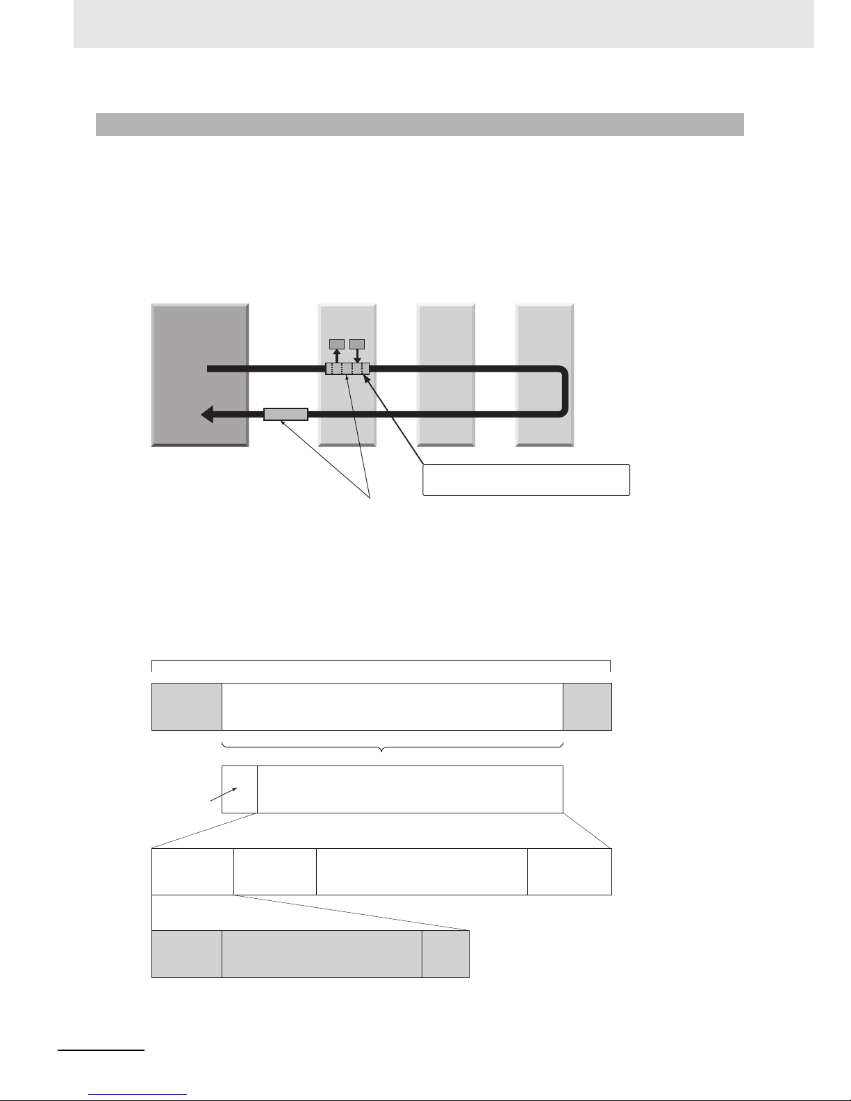
In EtherCAT, data is not sent to each node in the network, but the Ethernet frame is made to pass
through each node.
As the frame passes through, data is read and written at each node in the node's own area inside the
frame in several nanoseconds.
The Ethernet frame that was sent by the EtherCAT master passes through all the EtherCAT slaves
without stopping midway. Then, the frame is sent back by the final slave, and passes through all the
slaves again before returning to the EtherCAT master.
This system ensures high-speed data transmission and realtime performance.
The periodic data exchange between the EtherCAT master and EtherCAT slaves is performed with the
"EtherCAT telegrams" that are stored directly inside the Ethernet frame.
Each "EtherCAT telegram" consists of an address, data and working counter (check bit) for one or more
slaves.
If we compare an Ethernet frame to a train, EtherCAT telegrams can be considered as the carriages.
1-2-2 EtherCAT System
EtherCAT master
Slave Slave
Slave
Ethernet frame
IN
OUT
Data
• Reading of output data addressed to self
• Writing of input data
Ethernet
header
CRC
Ethernet data (Max. of 1,498 bytes)
Data
Datagram
header
WKC
1…n EtherCAT telegram
EtherCAT
header
1st EtherCAT
telegram
2nd EtherCAT
telegram
n th EtherCAT
telegram
. . . . .
Ethernet frame
Ethernet frame
WKC: Working counter
Page 28
1 - 5
1 EtherCAT Network
EtherCAT Communication Unit USER’S MANUAL (3G3AX-MX2-ECT)
1-2 Overview of EtherCAT
1
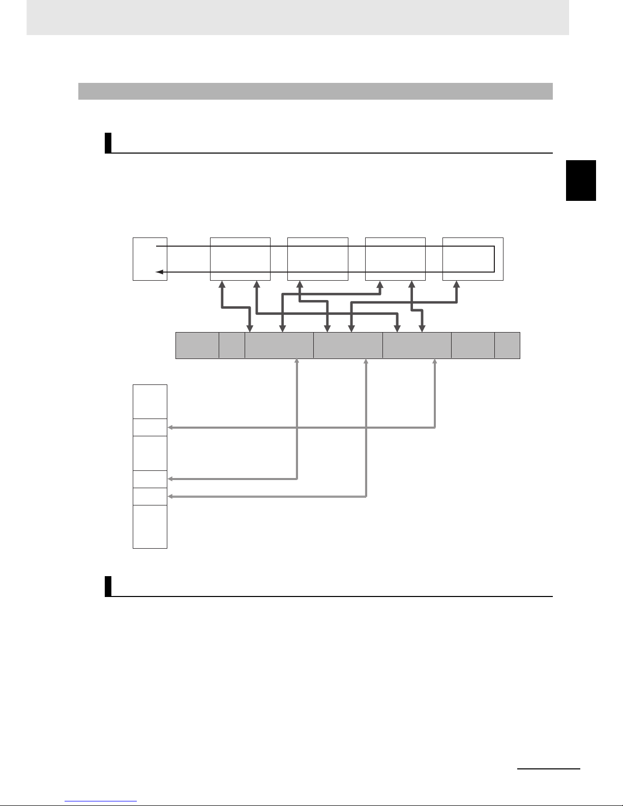
1-2-3 EtherCAT Communication Types
EtherCAT provides the following two types of communication functions.
This is cyclic (I/O) communication.
The EtherCAT Master Unit maps logical process data space (cyclic data space) to each slave node,
and realizes cyclic (I/O) communications with Slave Units.
This is message communication.
The EtherCAT Master Unit transmits commands to Slave Units, and the sSave Units return responses
to the EtherCAT Master Unit.
The data below is sent and received.
• Read and write process data
• Slave settings
• Monitor slave state
1-2-3 EtherCAT Communication Types
Process data communications functions (PDO communications)
Mailbox communication function (SDO communications)
EtherCAT master
Slave
Ethernet frame
Slave Slave
Slave
Ethernet
header
EtherCAT
header
1st EtherCAT
telegram
2nd EtherCAT
telegram
3rd EtherCAT
telegram
CRC
• • •
Logic process data
Data a
Data b
Data c
• • •• • •• • •
Page 29
1 EtherCAT Network
1 - 6
EtherCAT Communication Unit USER’S MANUAL (3G3AX-MX2-ECT)
1-3 EtherCAT System Configuration
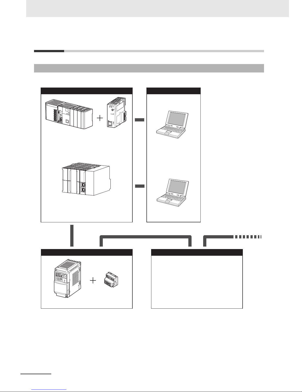
A typical system configuration is shown below.
1-3-1 System Configuration
EtherCAT
Communication Unit
3G3AX-MX2-ECT
SYSDRIVE
3G3MX2 series
EtherCAT slaveEtherCAT slave
Communications
cable
EtherCAT slaveEtherCAT slave
Other slaves
Servo Drive
Digital I/O
Analog I/O
Pulse input, etc
Position Control
Unit
CJ1W-NCx82
Programmable
Controller
SYSMAC CJ2
CX-One FA Integrated
Tool Package
or
Configuration ToolConfiguration Tool
EtherCAT masterEtherCAT master
Machine Automation Controller
NJ501-1x00 series
Sysmac Studio
or
Page 30

1 - 7
1 EtherCAT Network
EtherCAT Communication Unit USER’S MANUAL (3G3AX-MX2-ECT)
1-3 EtherCAT System
Configuration
1
1-3-2 Overview of Component Equipment
The overview of each structural device is as follows.
EtherCAT master
Manages the EtherCAT network, and performs slave status monitoring and data exchange with the
slaves.
EtherCAT slave
Receives data from the Master Unit and sends data to the Master Unit across the EtherCAT
network. The sent and received data can be output externally, input from an external source, or used
to perform various types of control for slave equipment.
The EtherCAT slave types shown below are available.
• Field network slaves
Slave devices that perform sequence control.
Examples: Digital I/O slaves, analog I/O slaves
• Motion network slaves
Slave devices that perform motion control.
Examples: Servo Units, Inverter Units
When this 3G3AX-MX2-ECT EtherCAT Communication Unit is installed on an inverter, it can be
operated as a motion network slave inverter.
Configuration tool
Computer software for setting the EtherCAT network and each slave.
Communications cable
The communications cable that connects the Master Unit with the Slave Units, and the Slave Units
to each other.
In an EtherCAT network, use an STP double-shield cable of Ethernet category 5 or higher.
EtherCAT Slave Information (ESI) file
A file in XML format that contains the information unique to the EtherCAT slave.
When this ESI file is loaded into the tool, it makes it easy to perform the various settings, such as the
mapping of the EtherCAT slave's I/O memory.
If OMRON's Configuration Tool is used, the ESI file is used together with the Configuration Tool, so
you need not worry about installing this file.
If a master by other manufacturer is connected, the ESI file must be loaded into a Configuration Tool
supporting that master.
1-3-2 Overview of Component Equipment
Page 31

1 EtherCAT Network
1 - 8
EtherCAT Communication Unit USER’S MANUAL (3G3AX-MX2-ECT)
Page 32

2 - 1
2
EtherCAT Communication Unit USER’S MANUAL (3G3AX-MX2-ECT)
This chapter explains information such as the mounting, wiring and setting methods for
the EtherCAT Communication Unit.
2-1 Part Names and Settings for the EtherCAT Communication Unit . . . . . . . 2-2
2-1-1 Part Names . . . . . . . . . . . . . . . . . . . . . . . . . . . . . . . . . . . . . . . . . . . . . . . . . . . . 2-2
2-1-2 Status Indicator Names . . . . . . . . . . . . . . . . . . . . . . . . . . . . . . . . . . . . . . . . . . 2-3
2-1-3 Rotary Switches for Node Address Setting . . . . . . . . . . . . . . . . . . . . . . . . . . . . 2-4
2-1-4 Communications Connector . . . . . . . . . . . . . . . . . . . . . . . . . . . . . . . . . . . . . . . 2-5
2-1-5 Recommended Products . . . . . . . . . . . . . . . . . . . . . . . . . . . . . . . . . . . . . . . . . 2-6
2-1-6 Connection between Communications Cables and Connectors . . . . . . . . . . . . 2-7
2-2 Basic Usage Procedures and Configuration Example . . . . . . . . . . . . . . . . 2-8
2-2-1 Basic Usage Procedures . . . . . . . . . . . . . . . . . . . . . . . . . . . . . . . . . . . . . . . . . 2-8
2-2-2 System Configuration Example . . . . . . . . . . . . . . . . . . . . . . . . . . . . . . . . . . . . . 2-9
2-3 CJ1W-NCx82 Master Setting . . . . . . . . . . . . . . . . . . . . . . . . . . . . . . . . . . . . 2-11
2-3-1 Mounting the CJ1W-NCx82 . . . . . . . . . . . . . . . . . . . . . . . . . . . . . . . . . . . . . . 2-11
2-3-2 CJ1W-NCx82 Setting . . . . . . . . . . . . . . . . . . . . . . . . . . . . . . . . . . . . . . . . . . . 2-11
2-4 NJ501-1x00 Master Setting . . . . . . . . . . . . . . . . . . . . . . . . . . . . . . . . . . . . . 2-12
2-4-1 Mounting the NJ501-1x00 . . . . . . . . . . . . . . . . . . . . . . . . . . . . . . . . . . . . . . . . 2-12
2-4-2 NJ501-1x00 Setting . . . . . . . . . . . . . . . . . . . . . . . . . . . . . . . . . . . . . . . . . . . . 2-12
2-5 Mounting and Wiring for the EtherCAT Communication Unit . . . . . . . . . 2-13
2-5-1 Mounting the EtherCAT Communication Unit . . . . . . . . . . . . . . . . . . . . . . . . . 2-13
2-5-2 Wiring the EtherCAT Communication Unit . . . . . . . . . . . . . . . . . . . . . . . . . . . 2-15
2-5-3 Wiring Conforming to EMC Directives . . . . . . . . . . . . . . . . . . . . . . . . . . . . . . 2-17
2-5-4 Node Address Settings for the EtherCAT Communication Unit . . . . . . . . . . . 2-18
2-6 SYSDRIVE MX2 Series Settings . . . . . . . . . . . . . . . . . . . . . . . . . . . . . . . . . 2-19
2-6-1 RUN Command Setting . . . . . . . . . . . . . . . . . . . . . . . . . . . . . . . . . . . . . . . . . 2-19
2-6-2 Frequency Reference Setting . . . . . . . . . . . . . . . . . . . . . . . . . . . . . . . . . . . . . 2-19
2-6-3 Reset Selection Setting . . . . . . . . . . . . . . . . . . . . . . . . . . . . . . . . . . . . . . . . . 2-19
2-7 Communication Starting and Operation Checking with CJ1W-NCx82 Master 2-20
2-7-1 Starting the System . . . . . . . . . . . . . . . . . . . . . . . . . . . . . . . . . . . . . . . . . . . . 2-20
2-7-2 Network Setup . . . . . . . . . . . . . . . . . . . . . . . . . . . . . . . . . . . . . . . . . . . . . . . . 2-20
2-7-3 Checking the Master Unit . . . . . . . . . . . . . . . . . . . . . . . . . . . . . . . . . . . . . . . . 2-20
2-7-4 Checking the Inverter and EtherCAT Communication Unit . . . . . . . . . . . . . . . 2-21
2-7-5 Checking the Operation . . . . . . . . . . . . . . . . . . . . . . . . . . . . . . . . . . . . . . . . . 2-21
2-8 Communication Starting and Operation Checking with NJ501-1x00 Master . . 2-22
2-8-1 Starting the System . . . . . . . . . . . . . . . . . . . . . . . . . . . . . . . . . . . . . . . . . . . . 2-22
2-8-2 Network Setup . . . . . . . . . . . . . . . . . . . . . . . . . . . . . . . . . . . . . . . . . . . . . . . . 2-22
2-8-3 Checking the NJ501-1x00 Master . . . . . . . . . . . . . . . . . . . . . . . . . . . . . . . . . . 2-26
2-8-4 Checking the Inverter and EtherCAT Communication Unit . . . . . . . . . . . . . . . 2-26
2-8-5 Checking the Operation . . . . . . . . . . . . . . . . . . . . . . . . . . . . . . . . . . . . . . . . . 2-26
Starting a Sample System
Page 33

2 Starting a Sample System
2 - 2
EtherCAT Communication Unit USER’S MANUAL (3G3AX-MX2-ECT)
2-1 Part Names and Settings for the
EtherCAT Communication Unit
2-1-1 Part Names
FG cable
Status indicator
(L/A IN, L/A OUT,
RUN, ERR)
Rotary switches
for node address
setting (× 10, × 1)
Communications connector
(IN, OUT)
Page 34

2 - 3
2 Starting a Sample System
EtherCAT Communication Unit USER’S MANUAL (3G3AX-MX2-ECT)
2-1 Part Names and Settings for the
EtherCAT Communication Unit
2
2-1-2 Status Indicator Names
The following table shows the EtherCAT status indicators and their meanings.
Additional Information
The timing of each flashing state of indicator is as follows.
2-1-2 Status Indicator Names
Name Color State Meaning
L/A IN Green OFF Link not established in physical layer
ON Link established in physical layer
Flickering In operation after establishing link
L/A OUT Green OFF Link not established in physical layer
ON Link established in physical layer
Flickering In operation after establishing link
RUN Green OFF Init state
Blinking Pre-operational state
Single flash Safe-operational state
ON Operational state
ERR Red OFF No error
Blinking Communications setting error
Single flash Synchronization error or communications data error
Double flash Application WDT timeout
Flickering Boot error
ON PDI WDT timeout
50
ms
200
ms
200
ms
200
ms
1000
ms
200
ms
200ms200
ms
1000
ms
200
ms
off
on
off
on
off
on
off
on
Flickering
Blinking
Single flash
Double flash
Page 35

2 Starting a Sample System
2 - 4
EtherCAT Communication Unit USER’S MANUAL (3G3AX-MX2-ECT)
These switches are used to set the node addresses of slaves in the EtherCAT network (decimal).
The 10s digit is set on the left rotary switch and the 1s digit is set on the right rotary switch.
The setting range is 00 to 99.
Note that the node address settings vary as shown below when the Host Controller is made by OMRON
and when it is made by other manufacturers.
Precautions for Correct Use
• The set node address is read only once when the inverter power supply is turned ON.
If the setting is changed after the power supply is turned ON, the new setting will not be used
until the next time that the power is turned ON.
• Do not change the setting on the rotary switches after the power supply has been turned ON.
• If node addresses overlap, an error occurs and the operation stops.
2-1-3 Rotary Switches for Node Address Setting
Set value for rotary switch
Set value for node address
OMRON Host Controller
Host Controller from another
manufacturer
00 The Host Controller set value is used as the
node address.
The Host Controller set value is used
regardless of the rotary switch set value.
01 to 99 The rotary switch set value is used as the
node address.
Node address setting
(× 1)
Node address setting
(× 10)
Page 36

2 - 5
2 Starting a Sample System
EtherCAT Communication Unit USER’S MANUAL (3G3AX-MX2-ECT)
2-1 Part Names and Settings for the
EtherCAT Communication Unit
2
2-1-4 Communications Connector
An Ethernet twisted-pair cable is connected to this connector.
The EtherCAT connector specifications are shown below.
• Electrical characteristics : Conform to IEEE 802.3.
• Connector structure : RJ45 8-pin modular connector (conforms to ISO 8877)
• Terminal arrangement :
2-1-4 Communications Connector
Pin No. Signal Abbreviation Function
1 Send data + TD + Send data +
2 Send data TD Send data
3 Receive data + RD+ Receive data +
4 Not used
5 Not used
6 Receive data RD Receive data
7 Not used
8 Not used
Hood Frame ground FG
1
8
Communications
connector (IN)
Communications
connector (OUT)
Page 37

2 Starting a Sample System
2 - 6
EtherCAT Communication Unit USER’S MANUAL (3G3AX-MX2-ECT)
For the communications cable, use a category 5 or higher straight type cable that is double-shielded
with aluminum tape and braided shielding. Use a shielded connector of category 5 or higher.
Precautions for Correct Use
• The maximum cable length between nodes is 100 m. However, some cables are specified for
less than 100 m. Generally, transmission performance of twisted wire condactor is lower than
that of solid wire. Confirm the details with the cable manufacturer.
• Use the shielded-type RJ45 connectors. When selecting a connector, confirm if it can be used
with the recommended cable. Confirm the following items: conductor size, conductor type
(solid wire or twisted wire), number of twisted pairs (2 or 4), outer diameter, etc.
Additional Information
If an Ethernet cable of category 5 or higher is used, communications will be possible even if the
cable is not shielded. However, we recommend a cable with double, aluminum tape and braided
shielding to ensure sufficient noise immunity.
2-1-5 Recommended Products
Connection cables and RJ45 connectors
Page 38

2 - 7
2 Starting a Sample System
EtherCAT Communication Unit USER’S MANUAL (3G3AX-MX2-ECT)
2-1 Part Names and Settings for the
EtherCAT Communication Unit
2
2-1-6 Connection between Communications Cables and Connectors
Connect the communications cable and the connector by wiring them straight as shown below.
* Connect both ends of cable shielded wires to the connector hoods.
Additional Information
There are 2 types of wiring standards for Ethernet cables: "T568A" and "T568B."
The figure above shows a wiring method conforming to the standard "T568A," but a wiring
method conforming to the standard "T568B" can also be used.
2-1-6 Connection between Communications Cables and Connectors
White-Green
Green
White-Orange
Blue
White-Blue
Orange
White-Brown
Brown
Connector
hood
1
2
3
4
5
6
7
8
Shielded cable*
Wire color
Pin No.
White-Green
Green
White-Orange
Blue
White-Blue
Orange
White-Brown
Brown
Connector
hood
1
2
3
4
5
6
7
8
Shielded cable*
Wire color
Pin No.
Page 39

2 Starting a Sample System
2 - 8
EtherCAT Communication Unit USER’S MANUAL (3G3AX-MX2-ECT)
2-2 Basic Usage Procedures and
Configuration Example
The basic usage procedures are shown below. For details on settings and connections, refer to the
manual for each Master Unit, and the slave manuals.
2-2-1 Basic Usage Procedures
Ref section 2-3-1.
Ref section 2-3-2.
CJ1W-NCx82
Master
1
Master Unit setting
2
Mounting and wiring of EtherCAT Communications Unit
3
Setting SYSDRIVE MX2 series
Checking communication start/operation
Network setup
Master Unit setting
ESI file setting
Mounting of EtherCAT Communications Unit
Wiring of EtherCAT Communications Unit
Setting reset selection
Setting RUN command
Setting frequency reference
Setting the node address of the EtherCAT
Communications Unit
4
Starting system
Checking Master Unit
Checking Inverter and EtherCAT Communications Unit
Checking operation
NJ501-1x00
Master
Ref section 2-4-1.
Ref section 2-4-2.
Ref section 2-5-3.
Ref section 2-5-1.
Ref section 2-5-2.
Ref section 2-6-3.
Ref section 2-6-1.
Ref section 2-6-2.
Ref section 2-7-3.
Ref section 2-7-1.
Ref section 2-7-2.
Ref section 2-7-5.
Ref section 2-7-4.
Ref section 2-8-3.
Ref section 2-8-1.
Ref section 2-8-2.
Ref section 2-8-5.
Ref section 2-8-4.
Page 40

2 - 9
2 Starting a Sample System
EtherCAT Communication Unit USER’S MANUAL (3G3AX-MX2-ECT)
2-2 Basic Usage Procedures and
Configuration Example
2
2-2-2 System Configuration Example
This chapter describes the usage procedures using the system configuration example shown below.
When configuring your actual system, select the units that are required for your system.
Master Unit : CJ2-series PLC + CJ1W-NCx82
Slave Unit ( 2) : 3G3MX2-A2001 + 3G3AX-MX2-ECT ( 2 sets)
(Notes) This Communication Unit can be used with all the capacities in the SYSDRIVE MX2 series.
Refer to 2-3 CJ1W-NCx82 Master Setting on page 2-11 for details on Unit installation and setting
method.
2-2-2 System Configuration Example
CJ1W-NCx82 Master
Master Unit Position Control Unit
(CJ1W-NCx82)
Slave Unit
First unit inverter
Node address 17
Slave Unit
2nd unit inverter
Node address 22
Communications cable 1
Length: 5 m
Communications cable 2
Length: 1 m
CJ2 series
CPU Unit
PC
CX-Programmer
Power
Supply Unit
Peripheral (USB)
port connection
RS-232C port connection
Used for data
setting
and
monitoring
• Monitoring status
• File management, etc
Page 41

2 Starting a Sample System
2 - 10
EtherCAT Communication Unit USER’S MANUAL (3G3AX-MX2-ECT)
Master Unit : Machine Automation Controller NJ501-1x00 series
Slave Unit ( 2) : 3G3MX2-A2001 + 3G3AX-MX2-ECT ( 2 sets)
(Notes) This Communication Unit can be used with all the capacities in the SYSDRIVE MX2 series.
Refer to 2-4 NJ501-1x00 Master Setting on page 2-12 for details on Unit installation and setting
method.
NJ501-1x00 Master
Slave Unit
First unit inverter
Node address 1
Slave Unit
2nd unit inverter
Node address 2
Communications cable 1
Length: 5 m
Communications cable 2
Length: 1 m
Peripheral (USB)
port connection
PC
Sysmac Studio
Power
Supply Unit
Used for data
setting
and
monitoring
• Monitoring status
• File management, etc
Master Unit
Machine Automation Controller
NJ501-1x00 series
Built-in EtherCAT port
Page 42

2 - 11
2 Starting a Sample System
EtherCAT Communication Unit USER’S MANUAL (3G3AX-MX2-ECT)
2-3 CJ1W-NCx82 Master Setting
2
2-3-1 Mounting the CJ1W-NCx82
2-3 CJ1W-NCx82 Master Setting
Connect the SYSMAC CJ2-series PLC and the CJ1W-NCx82 Master Unit by fitting their connectors
together. For specific details on mounting onto the SYSMAC Unit and the control panel of the SYSMAC
Unit, refer to the User Manual for the SYSMAC CJ2 series.
Perform the settings for the CJ1W-NCx82 Master Unit. For the setting method of each component, refer
to the manual for the Master Unit.
For the setting tool, use CX-Programmer Ver. 9.2 or later.
2-3-1 Mounting the CJ1W-NCx82
2-3-2 CJ1W-NCx82 Setting
Page 43

2 Starting a Sample System
2 - 12
EtherCAT Communication Unit USER’S MANUAL (3G3AX-MX2-ECT)
2-4 NJ501-1x00 Master Setting
Perform configuration of the NJ501-1x00 Master rack. For the specific configuration method, refer to
NJ-series CPU Unit Software User’s Manual (Cat No.W501).
Set the NJ501-1x00 Master. For the setting method for each part, refer to NJ-series CPU Unit Software
User’s Manual (Cat No.W501).
2-4-1 Mounting the NJ501-1x00
2-4-2 NJ501-1x00 Setting
Page 44

2 - 13
2 Starting a Sample System
EtherCAT Communication Unit USER’S MANUAL (3G3AX-MX2-ECT)
2-5 Mounting and Wiring for the EtherCAT
Communication Unit
2
2-5-1 Mounting the EtherCAT Communication Unit
2-5 Mounting and Wiring for the
EtherCAT Communication Unit
Mount the EtherCAT Communication Unit onto the inverter. Before performing this procedure, turn OFF
the main power supply of the inverter. Wait at least 10 minutes after the inverter's LED indicator lamp
and charge indicator have turned OFF, and then start the procedure.
This Communication Unit can be used with the inverter of unit version 1.1 or higher.
Make sure that the unit version of the inverter is 1.1 or higher.
The unit version of the inverter can be checked on the nameplate of the inverter.
(The unit version can not be checked on the CX-Drive.)
1
Loosen the mounting screw ( 1) from the optional board cover of the inverter front
panel.
2
Remove the optional board cover.
2-5-1 Mounting the EtherCAT Communication Unit
Removing the optional board cover from the inverter front panel
STOP
RESET
RUN
Hz
A
ALM
PRG
3G3MX2
INVERTER
RUN
PWR
SYSDR
IVE
Page 45

2 Starting a Sample System
2 - 14
EtherCAT Communication Unit USER’S MANUAL (3G3AX-MX2-ECT)
1
Mount the EtherCAT Communication Unit onto the location where the inverter optional
board cover that you removed was attached. Check that the connector is firmly
connected.
(Notes) When the EtherCAT Communication Unit is mounted, the main circuit and control circuit
terminals of the inverter are hidden. For this reason, be sure to wire the main circuit and control
circuit terminals before mounting the EtherCAT Communication Unit.
2
Tighten the mounting screw of the EtherCAT Communication Unit.
Tighten the bottom right screw of the EtherCAT Communication Unit with the specified torque
(46 N•cm, 4.7 kgf•cm).
Mounting the EtherCAT Communication Unit onto the inverter
STOP
RESET
RUN
Hz
A
ALM
PRG
3G3MX2
INVERTER
RUN
PWR
SYSDRIVE
Page 46

2 - 15
2 Starting a Sample System
EtherCAT Communication Unit USER’S MANUAL (3G3AX-MX2-ECT)
2-5 Mounting and Wiring for the EtherCAT
Communication Unit
2
2-5-2 Wiring the EtherCAT Communication Unit
1
Ground the FG cable of the EtherCAT Communication Unit.
Cut the ground wire of the unit's FG cable to an appropriate length and ground it to the closest
possible ground location. Also refer to the inverter manual.
Perform the wiring for the communications cables.
Determine the number and length of communications cables that are appropriate for your system
configuration.
Each communications cable between the nodes (and between the master and the nodes) must be no
longer than 100 m.
In the system configuration example used in this chapter, a cable of 5 m is prepared for
communications cable 1, and a cable of 1 m is prepared for communications cable 2.Connect an RJ45
connector to both ends of the communications cable by wiring them straight. Connect both ends of the
shielded wires of the cable to the hoods.
For details on preparing the cables, refer to 2-1-6 Connection between Communications Cables and
Connectors on page 2-7.
Connecting the ground cable of the EtherCAT Communication Unit
2-5-2 Wiring the EtherCAT Communication Unit
Preparing the communications cables
STOP
RESET
RUN
Hz
A
ALM
PRG
3G3MX2
INVERTER
RUN
PWR
SYSDRIVE
Page 47

2 Starting a Sample System
2 - 16
EtherCAT Communication Unit USER’S MANUAL (3G3AX-MX2-ECT)
Securely connect the EtherCAT communication cable connector to the EtherCAT Communication Unit
by inserting the connector all the way until it clicks.
Connect the communication cable from the EtherCAT master side to the communication connector IN
of the Communication Unit.
Connect the communication connector OUT to the communication connector IN of the next EtherCAT
slave.
Do not connect the communication connector OUT of the last EtherCAT slave.
Data will not be communicated correctly if the input/output are connected in reverse.
In the system configuration example used in this chapter, the connectors below are connected with the
communications cables.
(Notes) Do not connect anything to 2nd inverter OUT.
If a slave other than this product is used in your system configuration, set the unit in the same way by
referring to its User Manual.
• When constructing an EtherCAT network, take sufficient safety measures according to the standards.
We recommend that specialized constructors familiar with the safety measures and standards be
requested to perform the construction.
• Do not install EtherCAT network devices near devices generating noise.
If there is no choice but to install them down in an environment with a high level of noise, be sure to
take measures against the noise, such as covering each device in metal cases.
• To connect a cable to the communications connector of a device, insert it securely until the connector
of the communications cable is locked.
• Install and wire the communications cables separately from high-voltage electrical power lines.
• Do not install the cables near devices generating noise.
• Do not install the cables in high-temperature and high-humidity environments.
• Use the cables in locations without powder dust or oil mist.
Wiring the communications cables
Connecting from Connecting to
Communications cable 1 Master Unit 1st inverter IN
Communications cable 2 1st inverter OUT 2nd inverter IN
Precautions when constructing the network
Precautions when installing communications cables
Master Unit side
Slave Unit side
OUTOUT
ININ
OUT
IN
FG cable
Page 48

2 - 17
2 Starting a Sample System
EtherCAT Communication Unit USER’S MANUAL (3G3AX-MX2-ECT)
2-5 Mounting and Wiring for the EtherCAT
Communication Unit
2
2-5-3 Wiring Conforming to EMC Directives
To conform to the EMC directives (EN61800-3), conduct the wiring work for the EtherCAT
Communication Unit, so that it meets the wiring conditions described in this section. These conditions
are for conformance of products to the EMC directives when an EtherCAT Communication Unit is
installed on a SYSDRIVE MX2-series inverter. The installation and wiring conditions, however, may be
affected by the devices that are connected and wiring of the system where the EtherCAT
Communication Unit is installed. It is necessary to conform to the EMC directives as an overall system.
This section describes only the parts related to the addition of the EtherCAT Communication Unit.
Follow the instructions in the inverter manual for the inverter installation conditions, such as the power
supply line wiring, filter installation, and motor wiring clamps.
Install the 3 clamp cores shown below near the communications connectors of the communications
cables that are connected to the communications connector (IN) and the communications connector
(OUT). (If the communications cable on the OUT side is not connected, install them for the IN side only.)
Install the FG cable with the shortest possible wiring.
(Notes) The overall mounting appearance varies depending on the inverter capacity. Do not squeeze
the FG cable into the EtherCAT Communication Unit.
2-5-3 Wiring Conforming to EMC Directives
Wiring the communications cables
Symbol Name Manufacturer Model
FC1, FC2, FC3 Clamp core NEC TOKIN ESD-SR-160
Wiring the FG cable
STOP
RESET
RUN
Hz
A
ALM
PRG
3G3MX2
INVERTER
RUN
PWR
SYSDRIVE
200V
3PHASE
FC1
FC2
FC3
FG cable
Communications cable
(IN)
Communications cable
(OUT)
FC1
FC2
FC3
Page 49

2 Starting a Sample System
2 - 18
EtherCAT Communication Unit USER’S MANUAL (3G3AX-MX2-ECT)
Set the rotary switches of the EtherCAT Communication Unit to determine the node address.
In the system configuration example used in this chapter, the settings are as follows.
Notes on setting are provided below for each Master Unit.
<CJ1W-NCx82 Master>
1 The EtherCAT Communication Unit uses input and output areas for 5 node addresses.
For this reason, when using the inverter with a fixed allocation, set 5 or larger number to the node
address of the next unit.
2 Node addresses can be set in a range of 17 to 80. Make sure the node addresses set for the Unit do
not overlap with other slave.
3 For the restrictions related to CJ1W-NCx82 Master, refer to Position Control Units
CJ1W-NC281/NC481/NC881/NCF81/NC482/NC882 OPERATION MANUAL (Cat No.W487).
<NJ501-1x00 Master>
1 Node addresses can be set in a range of 1 to 99. Make sure the node addresses set for the Unit do
not overlap with other slave.
2 Unlike with the CJ1W-NCx82 master, the node address of the next unit can be set without intervals.
3 For the restrictions related to your NJ501-1x00, refer to NJ-series CPU Unit Software User’s Manual
(Cat No.W501).
(Notes) If a slave other than this product is also connected to the same network, set the unit by
referring to its User Manual. In such cases, check that the node addresses do not overlap with
other units.
2-5-4 Node Address Settings for the EtherCAT Communication Unit
Node address settings
Inverter CJ1W-NCx82 Master NJ501-1x00 Master
1st unit
Node address 17 1
Rotary switch x 10 Set to the 1 position. Set to the 0 position.
Rotary switch x 1 Set to the 7 position. Set to the 1 position.
2nd unit
Node address 22 2
Rotary switch x 10 Set to the 2 position. Set to the 0 position.
Rotary switch x 1 Set to the 2 position. Set to the 2 position.
Page 50

2 - 19
2 Starting a Sample System
EtherCAT Communication Unit USER’S MANUAL (3G3AX-MX2-ECT)
2-6 SYSDRIVE MX2 Series Settings
2
2-6-1 RUN Command Setting
2-6 SYSDRIVE MX2 Series Settings
To perform control from the Communication Unit, the parameter settings must be changed from the
front panel digital operator of the inverter.
In this procedure, the inverter power supply must be turned ON. When the power supply is turned ON,
the inverter may operate in unintended way. Check the condition of the wiring and system carefully
before starting the procedure.
Refer to the User Manual (Cat No.I570) for the SYSDRIVE MX2-series inverter for details on operating
the inverter parameter settings and for the meaning of the parameter values.
Change the control method for the RUN command.
Change the control method for the frequency reference.
Set the operation of the reset signal.
* If parameter C102 is not displayed, first set parameter b037 to 01.
2-6-1 RUN Command Setting
Parameter No. Function name Data Default value
A002 RUN Command Selection 1 04 (Optional boad) 02 (Digital Operator)
2-6-2 Frequency Reference Setting
Parameter No. Function name Data Default value
A001 Frequency Reference Selection 1 04 (Optional boad) 02 (Digital Operator)
2-6-3 Reset Selection Setting
Parameter No. Function name Data Default value
C102 Reset Selection 03 (Trip reset only) 00 (Trip reset at power-ON)
Page 51

2 Starting a Sample System
2 - 20
EtherCAT Communication Unit USER’S MANUAL (3G3AX-MX2-ECT)
2-7
Communication Starting and Operation
Checking with CJ1W-NCx82 Master
After completing the settings and wiring, turn ON the power and check that the communication starts.
The inverter power supply must be turned ON to set the inverter. When the power supply is turned ON,
the inverter may operate in unintended way. Check the condition of the wiring and system carefully
before starting the operation.
Check the condition of the wiring and system carefully, and then turn ON the power supply for all the
inverters and PLC. It does not matter whether the inverter or PLC power supply is turned ON first.
However, an error occurs unless the power supply for all the inverters is turned ON within a certain time
(All Registered Slave Participation Standby Time parameter of CJ1W-NCx82, default value is 10
seconds) after turning ON the PLC power supply.
Firstly,enter the network settings. Until the settings are performed, the indicators show "Initial
processing status" in the table below for both the Master Unit and the EtherCAT Communication Unit.
Start CX-Programmer, and double-click the target CJ1W-NCx82 in the I/O table to start the support
tool. When the support tool starts, the Network Auto Setup dialog box is displayed. Perform the network
setup in accordance with the dialog box instructions. If the Network Auto Setup dialog box is not
displayed automatically, start the dialog box by selecting Network Auto Setup from Network in the
support tool menu.
For details on network setting, refer to Position Control Units
CJ1W-NC281/NC481/NC881/NCF81/NC482/NC882 OPERATION MANUAL (Cat No.W487).
Check that the Master Unit has transitioned to normal operation from initial processing.
The indicators of the CJ1W-NCx82 make it easy to check the changes in status.
For details, refer to Position Control Units CJ1W-NC281/NC481/NC881/NCF81/NC482/NC882
OPERATION MANUAL (Cat No.W487).
2-7-1 Starting the System
2-7-2 Network Setup
2-7-3 Checking the Master Unit
7-segment
display
RUN ERC ERH
ECAT
RUN
ECAT
ERR
L/A
Initial processing Flashing ON OFF OFF OFF OFF ON
Normal operation “00” ON OFF OFF ON OFF Flashing
Page 52

2 - 21
2 Starting a Sample System
EtherCAT Communication Unit USER’S MANUAL (3G3AX-MX2-ECT)
2-7 Communication Starting and Operation
Checking with CJ1W-NCx82 Master
2
2-7-4 Checking the Inverter and EtherCAT Communication Unit
Check the POWER indicator and other indications of the inverter to confirm that power is being supplied
to the inverter.
Check the status indicators of the EtherCAT Communication Unit to see that the status has changed to
normal operation from initial processing.
1st unit
2nd unit
* If three or more units are connected, the status LEDs behave in the same way as the LEDs on the first unit,
except for the last unit.
L/A OUT on the last unit is always unlit.
Execute the PLC control program and check that the operation is normal.
2-7-4 Checking the Inverter and EtherCAT Communication Unit
L/A IN L/A OUT RUN ERR
Initial processing ON ON OFF OFF
Normal operation Flashing Flashing ON OFF
L/A IN L/A OUT RUN ERR
Initial processing ON OFF OFF OFF
Normal operation Flashing OFF ON OFF
2-7-5 Checking the Operation
Page 53

2 Starting a Sample System
2 - 22
EtherCAT Communication Unit USER’S MANUAL (3G3AX-MX2-ECT)
2-8 Communication Starting and Operation
Checking with NJ501-1x00 Master
After completing the settings and wiring, turn ON the power and check that the communication starts.
The inverter power supply must be turned ON to set the inverter. When the power supply is turned ON,
the inverter may operate in unintended way. Check the condition of the wiring and system carefully
before starting the operation.
Check the condition of the wiring and system carefully, and then turn ON the power supply for all the
inverters and NJ501-1x00 Master. It does not matter whether the inverter or NJ501-1x00 Master power
supply is turned ON first. However, an error occurs unless the power supply for all the inverters is
turned ON within a certain time (Wait time for slave startup parameter of NJ501-1x00, default value is
30 seconds) after turning ON the NJ501-1x00 power supply.
Firstly, enter the network settings. How to set the network is explained below by taking the "MX2-ECT
sample" project as an example.
1
Starting the Sysmac Studio
<Project Window>
Click the New Project Button, enter MX2-ECT sample under the Project name, and then click
the Create Button.
2-8-1 Starting the System
2-8-2 Network Setup
Page 54

2 - 23
2 Starting a Sample System
EtherCAT Communication Unit USER’S MANUAL (3G3AX-MX2-ECT)
2-8 Communication Starting and Operation
Checking with NJ501-1x00 Master
2
2-8-2 Network Setup
2
Registering an EtherCAT slave
<Controller Configurations and Setup Pane>
Right-click EtherCAT under the Configurations and Setup menu on the left side of the pane,
and open the Edit Pane.
When a group of items that can be registered as an EtherCAT slave appears on the right side of
the pane, select Frequency Inverter.
From the slave list on the right side of the pane, drag and drop 3G3AX-MX2-ECT onto Master at
the center of the pane, and the Unit will be registered as an EtherCAT slave.
drug & drop
Page 55

2 Starting a Sample System
2 - 24
EtherCAT Communication Unit USER’S MANUAL (3G3AX-MX2-ECT)
<Pane when 2 inverters are registered>
The pane after 2 inverters are registered is shown below.
3
Registering an IO map
Right-click I/O Map under the Configurations and Setup menu on the left side of the pane, and
open the Edit Pane.
With the NJ501-1x00 Master, data used in the control algorithms is treated as a set of variables.
If you want to assign a variable to each object that controls the inverter and use the assigned
variables in the control algorithms, define the variables on this pane.
<I/O Map Pane>
Page 56

2 - 25
2 Starting a Sample System
EtherCAT Communication Unit USER’S MANUAL (3G3AX-MX2-ECT)
2-8 Communication Starting and Operation
Checking with NJ501-1x00 Master
2
2-8-2 Network Setup
4
Building a program
Build the project program you created, so as to convert it to the format supported by the
NJ501-1x00 Master.
Select Build Controller from the Project Menu.
Confirm that the program that is built is with no errors.
5
Synchronizing with the CPU Unit
Transfer the program and settings created in Sysmac Studio to the NJ501-1x00 Master.
Go online and select Synchronization from the Controller Menu.
Click Transfer To Controller to transfer the program data.
When the transfer is completed successfully, the RUN LED indicator on the inverter turns ON.
The inverter is now ready.
<Synchronization Pane>
Page 57

2 Starting a Sample System
2 - 26
EtherCAT Communication Unit USER’S MANUAL (3G3AX-MX2-ECT)
Check that the NJ501-1x00 Master is operating normally in the RUN Mode.
Check the POWER indicator and other indications of the inverter to confirm that power is being supplied
to the inverter.
Check the status indicators of the EtherCAT Communication Unit to see that the status has changed to
normal operation from initial processing.
1st unit
2nd unit
* If three or more units are connected, the status LEDs behave in the same way as the LEDs on the first unit,
except for the last unit.
L/A OUT on the last unit is always unlit.
Execute the NJ501-1x00 Master control program and check that the operation is normal.
2-8-3 Checking the NJ501-1x00 Master
Status of NJ501-1x00 Master
Operating normally
User program is running User program is stopped
Front LED
indicators
PWR (Green) ON ON
RUN (Green) ON OFF
ERROR (Red) OFF OFF
2-8-4 Checking the Inverter and EtherCAT Communication Unit
L/A IN L/A OUT RUN ERR
Initial processing ON ON OFF OFF
Normal operation Flashing Flashing ON OFF
L/A IN L/A OUT RUN ERR
Initial processing ON OFF OFF OFF
Normal operation Flashing OFF ON OFF
2-8-5 Checking the Operation
Page 58

3 - 1
3
EtherCAT Communication Unit USER’S MANUAL (3G3AX-MX2-ECT)
This chapter explains the common slave specifications during EtherCAT
communication, and about the PDOs and SDOs.
3-1 Structure of CANopen over EtherCAT . . . . . . . . . . . . . . . . . . . . . . . . . . . . . 3-2
3-2 Communications Status Transitions . . . . . . . . . . . . . . . . . . . . . . . . . . . . . . 3-3
3-3 Process Data Objects (PDO) . . . . . . . . . . . . . . . . . . . . . . . . . . . . . . . . . . . . . 3-4
3-3-1 Outline . . . . . . . . . . . . . . . . . . . . . . . . . . . . . . . . . . . . . . . . . . . . . . . . . . . . . . . 3-4
3-3-2 PDO Mapping Settings . . . . . . . . . . . . . . . . . . . . . . . . . . . . . . . . . . . . . . . . . . . 3-4
3-3-3 Sync Manager PDO Assignment Settings . . . . . . . . . . . . . . . . . . . . . . . . . . . . 3-5
3-3-4 Fixed PDO Mapping . . . . . . . . . . . . . . . . . . . . . . . . . . . . . . . . . . . . . . . . . . . . . 3-5
3-4 Service Data Objects (SDO) . . . . . . . . . . . . . . . . . . . . . . . . . . . . . . . . . . . . . 3-6
3-4-1 Outline . . . . . . . . . . . . . . . . . . . . . . . . . . . . . . . . . . . . . . . . . . . . . . . . . . . . . . . 3-6
3-4-2 Abort Codes . . . . . . . . . . . . . . . . . . . . . . . . . . . . . . . . . . . . . . . . . . . . . . . . . . . 3-6
3-5 Emergency Messages . . . . . . . . . . . . . . . . . . . . . . . . . . . . . . . . . . . . . . . . . . 3-7
3-5-1 Outline . . . . . . . . . . . . . . . . . . . . . . . . . . . . . . . . . . . . . . . . . . . . . . . . . . . . . . . 3-7
3-5-2 Error Code List . . . . . . . . . . . . . . . . . . . . . . . . . . . . . . . . . . . . . . . . . . . . . . . . . 3-7
3-6 Sysmac Device Functions . . . . . . . . . . . . . . . . . . . . . . . . . . . . . . . . . . . . . . . 3-8
Common Slave Specifications
Page 59

3 Common Slave Specifications
3 - 2
EtherCAT Communication Unit USER’S MANUAL (3G3AX-MX2-ECT)
3-1 Structure of CANopen over EtherCAT
The figure below shows the structure of CANopen over EtherCAT (CoE).
Normally, multiple protocols can be transmitted using EtherCAT. In the EtherCAT Communication Unit
for MX2 inverters, the CANopen communication profile (CiA 301) that is popular in Europe, and the
drive profile (CiA 402) are used.
The object dictionary in the application layer contains parameters and application data as well as
information on the PDO mapping between the process data and inverter application.
The process data object (PDO) consists of objects in the object dictionary that can be mapped to the
PDO. The contents of the process data are defined by the PDO mapping.
Process data communications cyclically reads and writes the PDO. Mailbox communications (SDO)
uses asynchronous message communications where all objects in the object dictionary can be read
and written.
Process dataMailboxRegister
FMMU
SyncManager
SDO
(Mailbox)
PDO mapping
Object dictionary
PDO (Cyclic)
Inverter
EtherCAT data link layer
EtherCAT physical layer
Application layer
Communications
status transitions
Inverter application
Page 60

3 - 3
3 Common Slave Specifications
EtherCAT Communication Unit USER’S MANUAL (3G3AX-MX2-ECT)
3-2 Communications Status Transitions
3
3-2 Communications Status Transitions
The EtherCAT State Machine (ESM) of the EtherCAT slave is controlled by the EtherCAT Master.
State
SDO
communications
PDO
reception
PDO
transmission
Details
Initialization (Init) Not supported Not supported Not supported Communications are being initialized.
Communications are not possible.
Pre-Operational
(Pre-Op)
Supported Not suppor ted Not supported Only mailbox communications are possible in this
state. This state is entered after initialization has
been completed. It is used to initialize network
settings.
Safe-Operational
(Safe-Op)
Supported Not suppor ted Supported In this state, PDO transmissions are possible in
addition to mailbox communications. Cyclic
communications can be used to send information
such as status from the inverter.
Operational (Op) Supported Supported Supported This is a normal operating state. Cyclic
communications can be used to control the motor.
Safe-operational
Pre-operational
Initialization
Operational
Page 61

3 Common Slave Specifications
3 - 4
EtherCAT Communication Unit USER’S MANUAL (3G3AX-MX2-ECT)
3-3 Process Data Objects (PDO)
The process data objects (PDOs) are used to transfer data during cyclic communications in realtime.
There are two types of PDOs: reception PDOs (RxPDOs) which receive data from the controller, and
transmission PDOs (TxPDOs) which send statuses from the inverter to the Host Controller.
The EtherCAT application layer can hold multiple objects to enable the transferring of inverter process
data. The contents of the process data are described in the PDO mapping object and the Sync
Manager PDO assignment object.
The PDO mapping indicates the mapping for application objects (realtime process data) between the
object dictionary and PDO.
The number of mapped objects is described in sub-index 00 hex of the mapping table. In this mapping
table, 1600 to 17FF hex are for RxPDOs and 1A00 to 1BFF hex are for TxPDOs.
The following table is an example of PDO mapping.
3-3-1 Outline
3-3-2 PDO Mapping Settings
Host
Controller
TxPDO
Operation status, present value, etc
RxPDO
Operation command, target value, etc
Inverter
6TTT hex
ZZ hex
Index
Sub
6UUU hex UU hex
16
Object contents
1ZZZ hex
1ZZZ hex
1ZZZ hex
01 hex
02 hex
03 hex
6TTT hex TT hex
YYYY hex YY hex
8
8
6UUU hex
6VVV hex
6YYY hex
UU hex
VV hex
YY hex
TT hex
6ZZZ hex
Object A Object B
Object D
PDO_1
PDO length: 32 bits
Object dictionary
Mapping
objects
Application
objects
Object A
Object B
Object C
Object D
Object E
Page 62

3 - 5
3 Common Slave Specifications
EtherCAT Communication Unit USER’S MANUAL (3G3AX-MX2-ECT)
3-3 Process Data Objects (PDO)
3
3-3-3 Sync Manager PDO Assignment Settings
A Sync Manager channel consists of several PDOs. The Sync Manager PDO assignment objects
describe how these PDOs are related to the Sync Manager.
The number of PDOs is given in sub-index 00 hex of the Sync Manager PDO assignment table. In this
table, index 1C12 hex is for RxPDOs and 1C13 hex is for TxPDOs.
The following table is an example of Sync Manager PDO mapping.
This section describes the contents of fixed PDO mapping for MX2 inverters. The contents of fixed
PDOs cannot be changed.
3-3-3 Sync Manager PDO Assignment Settings
3-3-4 Fixed PDO Mapping
PDO mapping for speed control (independent profile)
RxPDO
(1701 hex)
5000 hex Command
5010 hex Frequency reference
TxPDO
(1B01 hex)
5100 hex Status
5110 hex Output frequency monitor
PDO mapping for speed control (CiA402 profile)
RxPDO
(1700 hex)
6040 hex Controlword
6042 hex vl target velocity
TxPDO
(1B00 hex)
6041 hex Statusword
6043 hex vl velocity demand
Index Sub Object contents
1C1Z hex
1C1Z hex
1C1Z hex
1A00 hex
1A01 hex
1A03 hex
PDO A
PDO B
PDO C
PDO F
PDO E
PDO D
PDO G
PDO A PDO B PDO D
1A00 hex
1A01 hex
1A02 hex
1A03 hex
1A04 hex
1A05 hex
1A06 hex
1 hex
2 hex
3 hex
Sync Manager PDO
assignment objects
Object dictionary
Mapping objects
Sync Manager entity Z
Page 63

3 Common Slave Specifications
3 - 6
EtherCAT Communication Unit USER’S MANUAL (3G3AX-MX2-ECT)
3-4 Service Data Objects (SDO)
The EtherCAT Communication Unit for MX2 inverters supports SDO communications as message
communications. SDO communications are used for setting objects and monitoring the status of MX2
inverters. Objects can be set and the status monitored by reading and writing data to the entries in the
object dictionary of the Host Controller.
The following table lists the abort codes for when an SDO communications error occurs.
3-4-1 Outline
3-4-2 Abort Codes
Val ue Meaning
05030000 hex Toggle bit not changed
05040000 hex SDO protocol timeout
05040001 hex Client/Server command specifier not valid or unknown
05040005 hex Out of memory
06010000 hex Unsupported access to an object
06010001 hex Attempt to read a write only object
06010002 hex Attempt to write to a read only object
06020000 hex The object does not exist in the object directory
06040041 hex The object can not be mapped into the PDO.
06040042 hex The number and length of the objects to be mapped would exceed the
PDO length.
06040043 hex General parameter incompatibility reason
06040047 hex General internal incompatibility in the device
06060000 hex Access failed due to a hardware error
06070010 hex Data type does not match, length of service parameter does not match
06070012 hex Data type does not match, length of service parameter too high
06070013 hex Data type does not match, length of service parameter too low
06090011 hex Subindex does not exist
06090030 hex Value range of parameter exceeded (only for write access)
06090031 hex Value of parameter written too high
06090032 hex Value of parameter written too low
06090036 hex Maximum value is less than minimum value
08000000 hex General error
08000020 hex Data cannot be transferred or stored to the application
08000021 hex Data cannot be transferred or stored to the application because of local control
08000022 hex Data cannot be transferred or stored to the application because of the present
device state
08000023 hex Object dictionary dynamic generation fails or no object dictionary is present
Page 64

3 - 7
3 Common Slave Specifications
EtherCAT Communication Unit USER’S MANUAL (3G3AX-MX2-ECT)
3-5 Emergency Messages
3
3-5-1 Outline
3-5 Emergency Messages
When an error or warning occurs in an MX2 inverter, an emergency message is sent to the master
using mailbox communications. An emergency message is not sent for a communications error.
You can select whether to send emergency messages by setting Diagnosis history (10F3 hex).
The default setting is to send emergency messages. (10F3 hex, sub-index: 05 hex (Flags) = 1)
Set the sub-index 05 hex (Flags) in object 10F3 hex to 0 every time the power is turned ON to disable
the sending of emergency messages.
Emergency messages consist of 8 bytes of data.
3-5-1 Outline
Byte 0 1 2 3 4 5 6 7
Meaning Error code
Error register
(Object 1001 hex)
Manufacturer specific error field
(reserved)
3-5-2 Error Code List
Error code Meaning Possible correction
5300 hex Error in the option and inverter
connection
• Check that the Communication Unit is mounted correctly
onto the inverter.
• The Communication Unit is faulty. Replace the
Communication Unit.
• If a trip reset was performed with the inverter, set the
inverter C102 to 3: Trip reset only, and turn the power
supply OFF and ON again.
• If an initialization mode change was performed with the
inverter, turn the inverter power supply OFF and ON again.
6341 hex PDO setting error A set value in PDO mapping is invalid. Check the value of
object 5200 and the AL Status code, and then review the PDO
assignment settings.
6331 hex EEPROM data error • An error was detected in data inside EEPROM when the
power supply was turned ON. Replace the Communication
Unit.
• The Diagnosis history cannot be saved because the
EEPROM has reached the end of its service life. There is
no effect on operations, but if you want to use the Diagnosis
history, replace the unit.
FF00 hex A warning occurred for the
inverter
Eliminate the cause and turn on the bit 7: Fault reset of 5000
hex (Command) or 6040 hex (Controlword).
FF01 hex A trip occurred for the inverter Eliminate the cause and turn on the bit 7: Fault reset of 5000
hex (Command) or 6040 hex (Controlword).
Page 65

3 Common Slave Specifications
3 - 8
EtherCAT Communication Unit USER’S MANUAL (3G3AX-MX2-ECT)
3-6 Sysmac Device Functions
The control device products designed according to the unified communication specifications and user
interface specifications applicable to OMRON's control devices are called Sysmac devices.
In addition, the functions of these devices are called Sysmac device functions.
The following explains the functions available when this product is combined with the Machine
Automation Controller including NJ Series or automation software.
The EtherCAT Communication Unit 3G3AX-MX2-ECT is a Sysmac device that, if the unit version is 1.1
or later, supports Sysmac device functions.
Sysmac error status
Errors generated by slaves are systematically defined in Sysmac devices. When Sysmac Studio is
used, error messages and remedial actions can be checked by following common operating
procedures.
Errors are notified by 2002 hex-01 hex: Sysmac Error status. If errors detected by the EtherCAT
Communication Unit are to be displayed in Sysmac Studio, 2002 hex-01 hex: Sysmac Error status must
be mapped to the PDO. By default, Sysmac Studio automatically maps 2002 hex-01 hex: Sysmac Error
status to the PDO by allocation of 1BFF hex : 512th transmit PDO Mapping.
Additional Information
• For the Sysmac error status, refer to 5-6-1 Manufacturer Specific Objects on page 5-16.
• For the errors displayed in Sysmac Studio, refer to A-5 Sysmac Error Status Codes on page
A-36.
Saving the node address settings
When the node address switch is set to 00, it means that the system is in the software setting mode and
the node address values set by Sysmac Studio become effective.
In the software setting mode, execute Write Slave Node Address on the EtherCAT Edit Screen of
Sysmac Studio to save the set values to the nonvolatile memory on the EtherCAT Communication Unit
side.
Page 66

3 - 9
3 Common Slave Specifications
EtherCAT Communication Unit USER’S MANUAL (3G3AX-MX2-ECT)
3-6 Sysmac Device Functions
3
Software setting
The value saved in the non-volatile memory on the slave side as SII (Slave Information Interface)
information becomes the node address.
Node address switch setting
The value set by the node address switches on the slave becomes the node address.
Displaying the serial number
The serial number saved in the nonvolatile memory on the Servo Drive side is displayed under 1018
hex-04 hex: Serial number. With controllers conforming to the Sysmac device functions, the network
configuration can be checked using this serial number.
To check the network configuration, set Setting = Actual device under Serial Number Check Method
on the EtherCAT Edit Screen of Sysmac Studio.
If the specified criteria cannot be met, a Network Configuration Verification Error will occur.
Additional Information
Since replacement of slave device can be detected, all slave parameters will be set without fail.
(1) While the power is off, set the node address
switches to 00.
(2) Write the set value of node address to SII on
the slave, from the master side.
(3) When the slave power is turned on, the set
value of node address is reflected in the register
address 0012 hex by the software.
(4) The EtherCAT master reads the set value at
the register address 0012 hex.
(5) The EtherCAT master writes the value at the
address 0012 hex to the address 0010 hex as
the node address.
Register: 0010 hex
EtherCAT
Slave Controller
Node address
switch
(2)
(3)
(1)
EtherCAT Slave
(EtherCAT Communication Unit)
(4)
(5)
Nonvolatile
memory
SII
EtherCAT Master
Register: 0012 hex
(2)
(1) While the power is off, set the node address
switches.
(2) When the slave power is turned on, the value
set by the node address switches is reflected
in the register address 0012 hex.
(3) The EtherCAT master reads the set value at
the register address 0012 hex.
(4) The EtherCAT master writes the value at the
address 0012 hex to the address 0010 hex as
the node address.
Register: 0010 hex
EtherCAT
Slave Controller
Node address
switch
(1)
EtherCAT Slave
(EtherCAT Communication Unit)
(3)
(4)
Nonvolatile
memory
SII
EtherCAT Master
Register: 0012 hex
Page 67

3 Common Slave Specifications
3 - 10
EtherCAT Communication Unit USER’S MANUAL (3G3AX-MX2-ECT)
Conforming to the ESI Specification (ETG.2000 S (R) V1.0.1)
The ESI Specification is a specification document defining the items described in the EtherCAT Slave
Information (ESI) file.
With controllers conforming to the Sysmac device functions, optional functions defined in the ESI
Specification can be used to specify backup parameters on the slave side.
Specified backup parameters on the slave side can be backed up and restored by Sysmac Studio.
SII data check
SII (Slave Information Interface) represents configuration information specific to each EtherCAT slave,
which is written to the nonvolatile memory in the EtherCAT slave.
With Sysmac device EtherCAT slaves, SII information is checked on the slave side.
If the slave cannot operated based on the SII information written, a SII verification error will occur. If the
error still occurs after turning the power OFF and then ON again, contact your OMRON sales
representative.
Precautions for Correct Use
Do not modify the SII information using a setting tool by other manufacturer.
Page 68

4 - 1
4
EtherCAT Communication Unit USER’S MANUAL (3G3AX-MX2-ECT)
This chapter describes the profiles that are used to control inverters.
4-1 Outline . . . . . . . . . . . . . . . . . . . . . . . . . . . . . . . . . . . . . . . . . . . . . . . . . . . . . . . 4-2
4-1-1 Function Selection . . . . . . . . . . . . . . . . . . . . . . . . . . . . . . . . . . . . . . . . . . . . . . 4-2
4-1-2 Object Mapping . . . . . . . . . . . . . . . . . . . . . . . . . . . . . . . . . . . . . . . . . . . . . . . . . 4-2
4-2 Control with the Position Control Unit . . . . . . . . . . . . . . . . . . . . . . . . . . . . . 4-4
4-2-1 Inverter Setting . . . . . . . . . . . . . . . . . . . . . . . . . . . . . . . . . . . . . . . . . . . . . . . . . 4-4
4-2-2 Object Mapping . . . . . . . . . . . . . . . . . . . . . . . . . . . . . . . . . . . . . . . . . . . . . . . . . 4-4
4-2-3 Control Method . . . . . . . . . . . . . . . . . . . . . . . . . . . . . . . . . . . . . . . . . . . . . . . . . 4-5
4-2-4 Sample Program . . . . . . . . . . . . . . . . . . . . . . . . . . . . . . . . . . . . . . . . . . . . . . . . 4-7
4-3 Control with the Independent Profile . . . . . . . . . . . . . . . . . . . . . . . . . . . . . 4-10
4-3-1 Inverter Setting . . . . . . . . . . . . . . . . . . . . . . . . . . . . . . . . . . . . . . . . . . . . . . . . 4-10
4-3-2 Profile Allocation . . . . . . . . . . . . . . . . . . . . . . . . . . . . . . . . . . . . . . . . . . . . . . . 4-10
4-3-3 Control Method . . . . . . . . . . . . . . . . . . . . . . . . . . . . . . . . . . . . . . . . . . . . . . . . 4-10
4-4 Control with the CiA402 Profile . . . . . . . . . . . . . . . . . . . . . . . . . . . . . . . . . . 4-12
4-4-1 Inverter Setting . . . . . . . . . . . . . . . . . . . . . . . . . . . . . . . . . . . . . . . . . . . . . . . . 4-12
4-4-2 Profile Allocation . . . . . . . . . . . . . . . . . . . . . . . . . . . . . . . . . . . . . . . . . . . . . . . 4-12
4-4-3 Control Method . . . . . . . . . . . . . . . . . . . . . . . . . . . . . . . . . . . . . . . . . . . . . . . . 4-12
4-5 Control with the PDO Free Format . . . . . . . . . . . . . . . . . . . . . . . . . . . . . . . 4-14
4-5-1 Inverter Setting . . . . . . . . . . . . . . . . . . . . . . . . . . . . . . . . . . . . . . . . . . . . . . . . 4-14
4-5-2 Object Mapping . . . . . . . . . . . . . . . . . . . . . . . . . . . . . . . . . . . . . . . . . . . . . . . . 4-14
4-5-3 Objects Allocation in Sysmac Studio . . . . . . . . . . . . . . . . . . . . . . . . . . . . . . . 4-15
4-5-4 Restrictions . . . . . . . . . . . . . . . . . . . . . . . . . . . . . . . . . . . . . . . . . . . . . . . . . . . 4-16
4-6 Trial operation via EtherCAT Communication Unit . . . . . . . . . . . . . . . . . . 4-17
Inverter Control
Page 69

4 Inverter Control
4 - 2
EtherCAT Communication Unit USER’S MANUAL (3G3AX-MX2-ECT)
4-1 Outline
This section describes how to use the EtherCAT Communication Unit to control the inverter.
Inverter control is performed by allocating a function object to a PDO.
These functions are limited depending on the combination with the used Master Unit.
*1 When using a Master Unit from another manufacturer, check yourself whether it supports the above functions.
*2 If you are using your NJ501-1x00 as the master, refer to the explanation on allocation in PDO free format.
Allocate the object that you want to use to a PDO with the procedure below.
1
Allocate the object to a PDO.
2
Assign the PDO to Sync Manager.
Use the tool of the Master Unit for allocation.
This unit uses the PDOs below to allocate the objects.
RxPDO (master to slave)
TxPDO (slave to master)
4-1-1 Function Selection
Type Details
Allocation when using CJ1W-NCx82 The fixed allocation when connected with OMRON's CJ1W-NCx82.
Independent profile OMRON's independently-developed function object.
Enables easy control of the inverter.
CiA402 drive profile A function object that conforms to the CiA402 drive profile.
PDO free format Objects can be freely allocated, including the above objects.
4-1-2 Object Mapping
PDO Mapping
PDO Details
1600 hex to 1604 hex
(1st receive PDO Mapping to
5th receive PDO Mapping)
Objects can be freely allocated. Up to 2 objects (maximum size of 4 bytes) can be
allocated to each PDO.
1700 hex
(257th receive PDO Mapping)
The fixed allocation that conforms to the CiA402 drive profile.
1701 hex
(258th receive PDO Mapping)
The fixed allocation of the independent profile.
PDO Details
1A00 to 1A04 hex
(1st transmit PDO Mapping to
5th transmit PDO Mapping)
Objects can be freely allocated. Up to 2 objects (maximum size of 4 bytes) can be
allocated to each PDO.
1B00 hex
(257th transmit PDO Mapping)
The fixed allocation that conforms to the CiA402 drive profile.
1B01 hex
(258th transmit PDO Mapping)
The fixed allocation of the independent profile.
1BFF hex
(512th transmit PDO Mapping)
By default, Sysmac Studio assigns 2002 hex: Sysmac error status.
Page 70

4 - 3
4 Inverter Control
EtherCAT Communication Unit USER’S MANUAL (3G3AX-MX2-ECT)
4-1 Outline
4
4-1-2 Object Mapping
In this unit, specify the PDOs that you want to use as follows.
Sync Manager
Sync ManagerAssignment
Sync Manager PDO assignment Details
1C12 hex Allocate RxPDO (master to slave).
Up to 5 RxPDOs can be allocated.
1C13 hex Allocate TxPDO (slave to master).
Up to 5 TxPDOs can be allocated.
Page 71

4 Inverter Control
4 - 4
EtherCAT Communication Unit USER’S MANUAL (3G3AX-MX2-ECT)
4-2 Control with the Position Control Unit
This section describes how to connect the OMRON CJ1W-NCx82 and the EtherCAT Communication
Unit to control the inverter.
Set the inverter parameters as follows.
* Select speed control or Simple position control by setting inverter parameter P012: Simple Position Control
Selection.
To use the Simple position control function, set the required parameters in accordance with the inverter manual.
* If parameter C102 is not displayed, set b037 to 01.
* Do not use motor 2 control of the inverter. The motor 1 control only can be used.
The object that will be used is allocated with the fixed settings below.
PDO mapping
Sync Manager assignment
4-2-1 Inverter Setting
Parameter Description
A001 Frequency Reference Selection 1 04: Optional board
A002 RUN Command Selection 1 04: Optional board
C102 Reset Selection 03: Trip reset only
P012 Simple Position Control Selection 00: Simple position control disabled
02: Simple position control enabled
4-2-2 Object Mapping
PDO Description
1701 hex 5000 (Command)
5010 (Frequency reference)
1600 hex 4016.6B (P060 Multi-step position command 0)
1601 hex 301F.40 (Multi-function input (Modbus communication register 1F01 hex coil data 0))
1B01 hex 5100 (Status)
5110 (Output frequency monitor)
1A00 hex 4010.59 (d030 Current position monitor)
1A01 hex 3010.29 (d006 Multi-function output monitor)
Sync Manager PDO assignment Description
1C12 hex 1701 (Fixed allocation of the independent profile)
1600 (Setting as above)
1601 (Setting as above)
1C13 hex 1B00 (Fixed allocation of the independent profile)
1A00 (Setting as above)
1A01 (Setting as above)
Page 72

4 - 5
4 Inverter Control
EtherCAT Communication Unit USER’S MANUAL (3G3AX-MX2-ECT)
4-2 Control with the Position Control Unit
4
4-2-3 Control Method
Control the inverter by operating the fixed mapping PDOs.
Control information (master to slave)
(Notes) n: Start address of the remote I/O output relay area that is assigned to the unit.
Status information (slave to master)
(Notes) m: Start address of the remote I/O input relay area that is assigned to the unit.
Command
The bit data for the command is shown below.
*1 Operates as a start bit when Simple position control is enabled.
Frequency reference
Multi-step Position command 0
4-2-3 Control Method
Word Meaning
n Control command
n + 1 Frequency reference
n + 2 Multi-step position command 0 (LSW)
n + 3 Multi-step position command 0 (MSW)
n + 4 Multi-function input
Word Meaning
m Status
m + 1 Output frequency monitor
m + 2 Current position monitor (LSW)
m + 3 Current position monitor (MSW)
m + 4 Multi-function output monitor
Bit and data information
7 10
Bit Name Meaning
0 Forward/stop *10: Stop
1: Forward command
1 Reverse/stop *10: Stop
1: Reverse command
7 Fault reset
: Resets an error or trip for the unit or inverter.
- (Reserved) The reserved area. Set 0.
Name Meaning
Frequency reference Specify the reference frequency in increments of 0.01 Hz. When a value is set that
exceeds the maximum frequency, operation is performed at the maximum frequency.
Setting range: 0 to maximum frequency
Name Meaning
Multi-step position command 0 Specify the value of inverter parameter P060: Multi-step position command 0. Values
outside the range are not applied and operation is performed with the previous value.
Setting range: Position range setting (reverse side) to position range setting (forward
side)
Page 73

4 Inverter Control
4 - 6
EtherCAT Communication Unit USER’S MANUAL (3G3AX-MX2-ECT)
Multi-function input
The bit data for the multi-function input information is shown below.
* Use by assigning a function to the multi-function input with the inverter parameters.
Status
The bit data for the status information is shown below.
Output frequency monitor
Current position monitor
Multi-function output monitor
The bit data for the multi-function output monitor information is shown below.
* Use by assigning a function to the multi-function output with the inverter parameters.
13 12 11 10 9 8 7
Bit Name Meaning
7 Multi-function input 1 0: OFF
1: ON
8 Multi-function input 2
9 Multi-function input 3
10 Multi-function input 4
11 Multi-function input 5
12 Multi-function input 6
13 Multi-function input 7
(Reserved) The reserved area. Set 0.
15 12 9 7 3 10
Bit Name Meaning
0 Forward operation in
progress
0: Stopped/during reverse operation
1: During forward operation
1 Reverse operation in
progress
0: Stopped/during forward operation
1: During reverse operation
3 Fault 0: No error or trip occurred for the unit or inverter
1: Error or trip occurred for the unit or inverter
7 Warning 0: No warning occurred for the unit or inverter
1: Warning occurred for the unit or inverter
9 Remote 0: Local (Operations from EtherCAT are disabled)
1: Remote (Operations from EtherCAT are enabled)
12 Frequency matching 0: During acceleration/deceleration
1: Frequency matched
15 Connection error between the
Optional Unit and inverter
0: Normal
1: Error (Cannot update data for the inverter. To restore, turn the power OFF
and then ON again.)
(Reserved) The reserved area. Set 0.
Name Meaning
Output frequency monitor Displays the output frequency in increments of 0.01 Hz.
Name Meaning
Current position monitor Displays the value of inverter parameter d030: Current position monitor.
6 10
Bit Name Meaning
0 Multi-function output P1/EDM 0: OFF
1: ON
1 Multi-function output P2
6 Multi-function relay output
(Reserved) The reserved area. Set 0.
Page 74

4 - 7
4 Inverter Control
EtherCAT Communication Unit USER’S MANUAL (3G3AX-MX2-ECT)
4-2 Control with the Position Control Unit
4
4-2-4 Sample Program
This section explains a configuration that uses CJ1W-NCx82 as the master, and one MX2 inverter on
which an EtherCAT Communication Unit (node address: 17) is mounted as the slave.
The shared parameter settings of CJ1W-NCx82 are as follows.
The control information and status information of the EtherCAT Communication Unit is allocated to the
addresses below.
• Control information (master to slave)
• Status information (slave to master)
4-2-4 Sample Program
Configuration
Parameter settings
Parameter name Set value
Remote I/O Output Memory Area Selection CIO area
First word of remote I/O Output memory area 3800
Remote I/O Input Memory Area Selection CIO area
First word of remote I/O Input memory area 3900
Word Address Meaning
n CIO 3800 Command
Bit 0: Forward/stop
Bit 1: Reverse/stop
Bit 7: Fault reset
n + 1 CIO 3801 Frequency reference (increments of 0.01 Hz)
Word Address Meaning
m CIO 3900 Command
Bit 0: During forward operation
Bit 1: During reverse operation
Bit 3: Fault
m + 1 CIO 3901 Output frequency monitor (increments of 0.01 Hz)
Page 75

4 Inverter Control
4 - 8
EtherCAT Communication Unit USER’S MANUAL (3G3AX-MX2-ECT)
Ladder program example
Time chart
0.00
Frequency
setting
Forward
During reverse
operation
Reverse
Frequency
reference
Forward/stop
(word n bit 0)
Reverse/stop
(word n bit 1)
Fault reset
(word n bit 7)
0.02
0.01
0.01 3900.01 30.00
3800.00
3900.00
3900.03
30.000.02
0.03
3800.07
3800.01
END
(001)
0.033900.03
30.00
30.00
3900.15
3900.15
MOV
(021)
D0000
3801
Fault
Fault
reset
Fault occurred
During forward
operation
Option - Inverter
connection fault
Option - Inverter
connection fault
Fault
occurred
Fault
occurred
Fault
occurred
Fault
Forward
Reverse
Fault reset
The frequency reference data in D00000
is forwarded to word n + 1.
(1)
(2) (3) (4) (5) (6) (7)
Frequency setting (0.00)
Forward (0.01)
Reverse (0.02)
During forward operation (word m bit 0)
During reverse operation (word m bit 1)
Frequency reference (word n + 1)
Fault occurred (30.00)
Fault reset (0.03)
Page 76

4 - 9
4 Inverter Control
EtherCAT Communication Unit USER’S MANUAL (3G3AX-MX2-ECT)
4-2 Control with the Position Control Unit
4
4-2-4 Sample Program
(1) When the "Frequency setting" contact is turned ON, the frequency reference data that is set in
D00000 is forwarded to the remote I/O output relay area (word n + 1).
(2) When the "Forward" contact is turned ON, "Forward/stop (word n bit 0)" of the remote I/O output
relay area turns ON and forward operation starts. During forward operation, "During forward
operation (word m bit 0)" of the remote I/O input relay area turns ON.
(3) When the "Forward" contact is turned OFF and after decelerating and stopping, "During forward
operation (word m bit 1)" of the remote I/O input relay area turns OFF.
(4) When the "Reverse" contact is turned ON, "Reverse/stop (word n bit 1)" of the remote I/O output
relay area turns ON and reverse operation starts. During reverse operation, "During reverse
operation (word m bit 1)" of the remote I/O input relay area turns ON.
(5) When the "Reverse" contact is turned OFF and after decelerating and stopping, "During reverse
operation (word m bit 1)" of the remote I/O input relay area turns OFF.
(6) When "Fault (word m bit 3)" of the remote I/O input relay area turns ON, "Fault occurred" turns ON.
(7) When the "Fault reset" contact is turned ON, "Fault reset (word n bit 7)" of the remote I/O output
relay area turns ON and the fault is cancelled.
Explanation of operations
Page 77

4 Inverter Control
4 - 10
EtherCAT Communication Unit USER’S MANUAL (3G3AX-MX2-ECT)
4-3 Control with the Independent Profile
This section describes how to use the OMRON profile to control the inverter.
The inverter parameters must be set to match the profile.
With the independent profile, set as follows.
* If parameter C102 is not displayed, set b037 to 01.
Assign the PDOs of the independent profile to Sync Manager.
The values below are the fixed mapping for the PDOs.
Control the inverter by operating the PDOs that allocate the profile.
Control information (master to slave)
Status information (slave to master)
4-3-1 Inverter Setting
Parameter Description
A001 Frequency Reference Selection 1 04: Optional boad
A002 RUN Command Selection 1 04: Optional boad
C102 Reset Selection 03: Trip reset only
4-3-2 Profile Allocation
Sync Manager PDO assignment Description
1C12 hex 1701 hex (Fixed allocation of the independent profile)
1C13 hex 1B01 hex (Fixed allocation of the independent profile)
PDO Description
1701 hex 5000 hex (Command)
5010 hex (Frequency reference)
1B01 hex 5100 hex (Status)
5110 hex (Output frequency monitor)
4-3-3 Control Method
IO format
Word Meaning
n Command
n + 1 Frequency reference
Word Meaning
m Status
m + 1 Output frequency monitor
Page 78

4 - 11
4 Inverter Control
EtherCAT Communication Unit USER’S MANUAL (3G3AX-MX2-ECT)
4-3 Control with the Independent Profile
4
4-3-3 Control Method
Command
Frequency reference
Status
The 16-bit data is as shown below.
Output frequency monitor
Bit and data information
7 10
Bit Name Meaning
0 Forward/stop 0: Stop
1: Forward command
1 Reverse/stop 0: Stop
1: Reverse command
7Fault reset
: Resets an error or trip for the unit or inverter.
- Reserved Set 0.
Name Meaning
Frequency reference Specify the frequency reference in increments of 0.01 Hz. When a value is set that
exceeds the maximum frequency, operation is performed at the maximum frequency.
Setting range: 0 to maximum frequency
15 12 9 7 3 10
Bit Name Meaning
0 During forward operation 0: Stopped/during reverse operation
1: During forward operation
1 During reverse operation 0: Stopped/during forward operation
1: During reverse operation
3 Fault 0: No error or trip occurred for the unit or inverter
1: No error or trip occurred for the unit or inverter
7 Warning 0: No warning occurred for the unit or inverter
1: Warning occurred for the unit or inverter
9 Remote 0: Local (Operations from EtherCAT are disabled)
1: Remote (Operations from EtherCAT are enabled)
12 Frequency matching 0: During acceleration/deceleration or stopped
1: Frequency matched
15 Connection error between the
Optional Unit and inverter
0: Normal
1: Error (Cannot update data for the inverter. To restore, turn the
power supply OFF and then ON again.)
Reserved Set 0.
Name Meaning
Output frequency monitor Displays the output frequency in increments of 0.01 Hz.
Page 79

4 Inverter Control
4 - 12
EtherCAT Communication Unit USER’S MANUAL (3G3AX-MX2-ECT)
4-4 Control with the CiA402 Profile
This section describes how to use the Velocity mode of the CiA402 drive profile to control the inverter.
The inverter parameters must be set to match the profile.
With the CiA402 profile, set as follows.
* After changing H004, turn the inverter power supply OFF and ON again.
* If parameter C102 is not displayed, set b037 to 01.
* Do not use motor 2 control of the inverter. The motor 1 control only can be used.
Assign the PDOs of the CiA402 profile to Sync Manager.
The values below are the fixed mapping for the PDOs.
Control the inverter by operating the PDOs that allocate the profile.
Control information (master to slave)
Status information (slave to master)
4-4-1 Inverter Setting
Parameter Description
A001 Frequency Reference Selection 1 04: Optional boad
A002 RUN Command Selection 1 04: Optional boad
H004 Motor Pole Number 1 2/4/6/8/10(Set to match the system.)
C102 Reset Selection 03 (Trip reset only)
4-4-2 Profile Allocation
Sync Manager PDO assignment Description
1C12 hex 1700 hex (Fixed allocation conforming to the CiA402 drive profile)
1C13 hex 1B00 hex (Fixed allocation conforming to the CiA402 drive profile)
PDO Description
1700 hex 6040 hex (Controlword)
6042 hex (vl target velocity)
1B00 hex 6041 hex (Statusword)
6043 hex (vl velocity demand)
4-4-3 Control Method
IO format
Word Meaning
n Controlword
n + 1 vl target velocity
Word Meaning
m Statusword
m + 1 vl velocity demand
Page 80

4 - 13
4 Inverter Control
EtherCAT Communication Unit USER’S MANUAL (3G3AX-MX2-ECT)
4-4 Control with the CiA402 Profile
4
4-4-3 Control Method
Controlword
The 16-bit data is as shown below.
* When Quick stop is set to 0 during operation, deceleration stop is made. After completely stopping, the next
operation is accepted.
vl target velocity
Statusword
The 16-bit data is as shown below.
vl velocity demand
Bit and data information
7 3210
Bit Name Meaning
0 Switch on The state is controlled by these bits.
For details, refer to 5-1-3 Command Coding on page 5-3.
1 Enable voltage
2 Quick stop
3 Enable operation
7Fault reset
Faults and warnings are cleared when this bit turns ON.
Reserved Set 0.
Name Meaning
vl target velocity Specify the command speed in rpm.
Setting range: maximum speed to +maximum speed
Specify the operation direction with a symbol (/+). When a value is set that exceeds
the maximum frequency, operation is performed at the maximum frequency.
9 76543210
Bit Name Meaning
0 Ready to switch on These bits indicate the state.
For details, refer to 5-1-4 State Coding on page 5-3.
1 Switched on
2 Operation enabled
3Fault
4 Voltage enabled
5 Quick stop
6 Switch on disabled
7 Warning 0: No warning occurred for the unit or inverter.
1: Warning occurred for the unit or inverter.
9 Remote 0: Control from Controlword is disabled.
1: Control from Controlword is enabled.
Reserved Not used.
Name Meaning
vl velocity demand Displays the operation speed in rpm.
The operation direction is expressed with a symbol (/+).
Page 81

4 Inverter Control
4 - 14
EtherCAT Communication Unit USER’S MANUAL (3G3AX-MX2-ECT)
4-5 Control with the PDO Free Format
Objects can be freely allocated to PDOs to create an independent profile.
If you use in combination with the OMRON independent profile or the CiA402 drive profile, you can
perform advanced control and monitoring.
To use your OMRON NJ501-1x00 as the master, allocate desired objects by referring to this section.
When using the OMRON independent profile, set A001, A002 and C102.
When using the CiA402 drive profile, set A001, A002, H004 and C102.
For details, refer to the previous sections.
Allocate the objects that you want to use to PDOs.
Set as follows to allocate the acceleration time and deceleration time to RxPDO and the current monitor
to TxPDO, based on the OMRON independent profile.
PDO mapping
Sync Manager assignment
Following from the above allocations, the IO format is as follows.
Control information (master to slave)
4-5-1 Inverter Setting
4-5-2 Object Mapping
Setting example
PDO Description
1600 hex
(1st receive PDO Mapping)
4011.26 (F002 Acceleration time setting 1)
1601 hex
(2nd receive PDO Mapping)
4011.28 (F003 Deceleration time setting 1)
1A00 hex
(1st transmit PDO Mapping)
3010.24 (d002 Output current monitor)
Sync Manager PDO assignment Description
1C12 hex 1701 hex (Fixed allocation of the independent profile)
1600 hex (Setting as above)
1601 hex (Setting as above)
1C13 hex 1B01 hex (Fixed allocation of the independent profile)
1A00 hex (Setting as above)
Word Meaning
n Command
n + 1 Frequency reference
n + 2 Acceleration time setting 1 (LSW)
n + 3 Acceleration time setting 1 (MSW)
n + 4 Deceleration time setting 1 (LSW)
n + 5 Deceleration time setting 1 (MSW)
Page 82

4 - 15
4 Inverter Control
EtherCAT Communication Unit USER’S MANUAL (3G3AX-MX2-ECT)
4-5 Control with the PDO Free Format
4
4-5-3 Objects Allocation in Sysmac Studio
Status information (slave to master)
In Sysmac Studio, you can edit the PDO map settings for each slave.
Click Edit PDO Map Settings in the Configurations and Setup of the EtherCAT slave to open the Edit
PDO Map Settings pane.
Word Meaning
m Status
m + 1 Output frequency monitor
m + 2 Output current monitor
4-5-3 Objects Allocation in Sysmac Studio
Page 83

4 Inverter Control
4 - 16
EtherCAT Communication Unit USER’S MANUAL (3G3AX-MX2-ECT)
To allocate an object to a PDO in Sysmac Studio, select Output (or Input) for one of 1st receive PDO
Mapping to 5th receive PDO Mapping (or 1st transmit PDO Mapping to 5th transmit PDO Mapping),
right-click Add PDO Entry on the right side of the screen, and then select a desired object from the list.
When Output (or Input) is selected, the applicable PDO among 1st receive PDO Mapping to 5th
receive PDO Mapping (or 1st transmit PDO Mapping to 5th transmit PDO Mapping) will be allocated to
Sync Manager.
Note that up to 5 PDOs can be selected each for the target of Output (or Input).
Add PDO Entry
In the example shown below, Jogging Frequency (Index: 3012.5Dh) and Manual Torque Boost
Frequency 1 (Index: 3012.62h) are allocated to 1st receive PDO Mapping.
The PDO free format has the restrictions that are described below.
• Up to 2 objects can be allocated to each PDO from 1600 to 1604 hex and 1A00 to 1A04 hex. Keep
the total size of the allocated objects to within 4 bytes.
• Up to 5 PDOs each can be allocated to 1C12 and 1C13.
• An object from 5000 to 5999 cannot be allocated to RxPDO (master to slave) together with an object
from 6000 to 6999.
• An RxPDO that combines an object from 5000 to 5999 with an object from 6000 to 6999 cannot be
allocated to 1C12 hex of Sync Manager.
• The inverter parameters (objects 3000 to 3999 and 4000 to 4999) that can be allocated to RxPDO
(master to slave) are limited to those that can be changed during operation.
• It is not possible to allocate only the LSW or only the MSW to RxPDO or TxPDO.
• The greater the number of RxPDOs or TxPDOs is, the longer the data updating cycle becomes.
Normally the data is updated every 4 ms, but it can increase to every 6 ms depending on the number.
4-5-4 Restrictions
Page 84

4 - 17
4 Inverter Control
EtherCAT Communication Unit USER’S MANUAL (3G3AX-MX2-ECT)
4-6 Trial operation via EtherCAT Communication Unit
4
4-6 Trial operation via EtherCAT
Communication Unit
You can use the "Test Operation" function of your parameter setting tool (CX-Drive, etc.) to operate the
inverter on a trial basis.
Before performing trial operation of the inverter via the EtherCAT Communication Unit, make sure
EtherCAT network communications have been established properly. The main purpose of trial operation
is to confirm that the system operates correctly from the electrical viewpoint. Perform trial operation
after confirming safety around the devices.
If an error occurs during trial operation, remove the error by referring to Chapter 6, Handling of Errors
and Maintenance or the User's Manual for MX2 Series, and resume operation after conforming safety.
How to perform trial operation using a parameter setting tool
1
Start your parameter setting tool and make online connection via EtherCAT.
2
Select the Test Operation function.
3
Set a desired frequency, acceleration time and deceleration time, and then select
Forward or Reverse and run the motor.
The motor will keep running until Stop is selected.
Page 85

4 Inverter Control
4 - 18
EtherCAT Communication Unit USER’S MANUAL (3G3AX-MX2-ECT)
Page 86

5 - 1
5
EtherCAT Communication Unit USER’S MANUAL (3G3AX-MX2-ECT)
This chapter explains about the CiA402 drive profile.
5-1 Inverter State Control . . . . . . . . . . . . . . . . . . . . . . . . . . . . . . . . . . . . . . . . . . . 5-2
5-1-1 State Machine . . . . . . . . . . . . . . . . . . . . . . . . . . . . . . . . . . . . . . . . . . . . . . . . . . 5-2
5-1-2 State Descriptions . . . . . . . . . . . . . . . . . . . . . . . . . . . . . . . . . . . . . . . . . . . . . . . 5-3
5-1-3 Command Coding . . . . . . . . . . . . . . . . . . . . . . . . . . . . . . . . . . . . . . . . . . . . . . . 5-3
5-1-4 State Coding . . . . . . . . . . . . . . . . . . . . . . . . . . . . . . . . . . . . . . . . . . . . . . . . . . . 5-3
5-2 Modes of Operation . . . . . . . . . . . . . . . . . . . . . . . . . . . . . . . . . . . . . . . . . . . . 5-4
5-3 Velocity Mode . . . . . . . . . . . . . . . . . . . . . . . . . . . . . . . . . . . . . . . . . . . . . . . . . 5-5
5-4 Object Dictionary . . . . . . . . . . . . . . . . . . . . . . . . . . . . . . . . . . . . . . . . . . . . . . 5-6
5-4-1 Object Dictionary Area . . . . . . . . . . . . . . . . . . . . . . . . . . . . . . . . . . . . . . . . . . . 5-6
5-4-2 Data Types . . . . . . . . . . . . . . . . . . . . . . . . . . . . . . . . . . . . . . . . . . . . . . . . . . . . 5-6
5-4-3 Object Description Format . . . . . . . . . . . . . . . . . . . . . . . . . . . . . . . . . . . . . . . . 5-6
5-5 CoE Communications Area . . . . . . . . . . . . . . . . . . . . . . . . . . . . . . . . . . . . . . 5-8
5-5-1 Communication Objects . . . . . . . . . . . . . . . . . . . . . . . . . . . . . . . . . . . . . . . . . . 5-8
5-5-2 PDO Mapping Objects . . . . . . . . . . . . . . . . . . . . . . . . . . . . . . . . . . . . . . . . . . 5-11
5-5-3 Sync Manager Communication Objects . . . . . . . . . . . . . . . . . . . . . . . . . . . . . 5-13
5-6 Manufacturer Specific Area . . . . . . . . . . . . . . . . . . . . . . . . . . . . . . . . . . . . . 5-16
5-6-1 Manufacturer Specific Objects . . . . . . . . . . . . . . . . . . . . . . . . . . . . . . . . . . . . 5-16
5-6-2 Inverter Parameter Objects . . . . . . . . . . . . . . . . . . . . . . . . . . . . . . . . . . . . . . . 5-17
5-6-3 Independent Profile Objects . . . . . . . . . . . . . . . . . . . . . . . . . . . . . . . . . . . . . . 5-19
5-7 Device Profile area . . . . . . . . . . . . . . . . . . . . . . . . . . . . . . . . . . . . . . . . . . . . 5-22
5-7-1 Drive Profile Objects . . . . . . . . . . . . . . . . . . . . . . . . . . . . . . . . . . . . . . . . . . . . 5-22
CiA402 Drive Profile
Page 87

5 CiA402 Drive Profile
5 - 2
EtherCAT Communication Unit USER’S MANUAL (3G3AX-MX2-ECT)
5-1 Inverter State Control
The state of the MX2 inverter is controlled by using the Controlword (6040 hex). Control state is given in
the Statusword (6041 hex).
The state of the MX2 inverter changes as shown below.
Each box indicates a state, while numbers 2 to 10 and 15 indicate the state control commands.
For details on the states, refer to 5-1-2 State Descriptions on page 5-3, and for details on the command
codings, refer to 5-1-3 Command Coding on page 5-3.
(Notes) The Quick stop active state is not supported. If Quick stop is enabled in the Operation enable state,
transition 9 is executed.
5-1-1 State Machine
Power turned OFF or reset
Not ready to switch on
1: After initialization is completed
Start
0: After the main power supply is turned on
Switch on
disabled
Fault
Shutdown: 2
7: Disable Voltage
Ready to
switch on
Switch on: 3
Switched on
6: Shutdown
Disable Voltage: 10
Enable operation: 4
5: Disable
operation
15: Fault reset
Operation
enabled
8: Shut down
9: Disable Voltage
13: Error occurs
Fault
reaction active
14: Error
response
operation
completed
Page 88

5 - 3
5 CiA402 Drive Profile
EtherCAT Communication Unit USER’S MANUAL (3G3AX-MX2-ECT)
5-1 Inverter State Control
5
5-1-2 State Descriptions
The state is controlled by combining the bits in Controlword (6040 hex), as shown in the following table.
(Notes) fr = Fault reset, eo = Enable operation, qs = Quick stop, ev = Enable voltage, so = Switch on
*1 The state automatically transitions to the Enable operation state after the Switch on state.
*2 Operation when bit 7: Fault reset turns ON.
Fault state : Fault are cleared and the state transitions to Switch on disabled.
: If there are any warnings (6401 hex: Statusword bit 7), they are reset.
State other than Fault : If there are any warnings (6041 hex: Statusword bit 7), they are reset.
: The state will change according to command bits 0 to 3.
*3 When Fault reset is executed with bit 7, set the bit back to 0 before giving the next command.
The state is indicated by the combination of bits in Statusword (6041 hex), as shown in the following
table.
(Notes) sod = Switch on disabled, qs = Quick stop, ve = Voltage enabled, f = Fault, oe = Operation enabled,
so = Switched on, rtso = Ready to switch on
5-1-2 State Descriptions
State Details
Not ready to switch on The power supply is turned ON and initialization is being executed.
Switch on disabled Initialization has been completed.
Parameters can be set.
Ready to switch on Parameters can be set.
Switched on Parameters can be set.
Operation enabled Inverter can be controlled.
Parameters can be set.
Fault reaction active There was an error in the inverter and the cause is being determined.
Parameters can be set.
Fault There is an error in the inverter.
Parameters can be set.
5-1-3 Command Coding
Command
Controlword bit
Transition
Bit 7
fr
Bit 3
eo
Bit 2
qs
Bit 1
ev
Bit 0
so
Shutdown - - 1 1 0 2, 6, 8
Switch on - 0 1 1 1 3
Switch on +
enable operation
-1111
3 + 4
*1
Disable voltage - - - 0 - 7, 9, 10
Quick stop - - 0 1 - 7, 9, 10
Disable operation - 0 1 1 1 5
Enable operation - 1 1 1 1 4
Fault reset
0
1
*2*3
----15
5-1-4 State Coding
State
Bit 6
sod
Bit 5
qs
Bit 4
ve
Bit 3
f
Bit 2
oe
Bit 1
so
Bit 0
rtso
Not ready to switch on 0 0 - 0 0 0 0
Switch on disabled 1 1 - 0 0 0 0
Ready to switch on 0 1 - 0 0 0 1
Switched on 0 1 1 0 0 1 1
Operation enabled 0 1 1 0 1 1 1
Fault reaction active 0 1 - 1 1 1 1
Fault 01-1000
Page 89

5 CiA402 Drive Profile
5 - 4
EtherCAT Communication Unit USER’S MANUAL (3G3AX-MX2-ECT)
5-2 Modes of Operation
The operation mode indicated below is supported.
* vl: Velocity mode
The operation mode is set in Modes of operation (6060 hex). In addition, the operation mode is given in
Modes of operation display (6061 hex).
The operation modes supported by the inverter can be checked in Supported drive modes (6502 hex).
Page 90

5 - 5
5 CiA402 Drive Profile
EtherCAT Communication Unit USER’S MANUAL (3G3AX-MX2-ECT)
5-3 Velocity Mode
5
5-3 Velocity Mode
In this operation mode, the output speed of the inverter can be controlled.
• Related objects
Index Name Details
6040 hex Controlword Gives commands to the inverter.
6042 hex vl target velocity Gives speed commands to the inverter.
6046 hex vl velocity min max amount Sets the maximum speed and minimum speed that can be
output.
6048 hex vl velocity acceleration Sets the acceleration time.
6049 hex vl velocity deceleration Sets the deceleration time.
6041 hex Statusword Sets the status of the inverter.
6043 hex vl velocity demand Gives the command speed.
6044 hex vl velocity actual value Gives the output speed.
vl velocity min/max amount (6046 hex)
vl velocity acceleration (6048 hex)
Ramp
function
Velocity
limit
function
vl velocity deceleration (6049 hex)
Velocity
control
function
vl target velocity (6042 hex)
vl velocity
demand (6043 hex)
vl velocity actual
value (6044 hex)
Page 91

5 CiA402 Drive Profile
5 - 6
EtherCAT Communication Unit USER’S MANUAL (3G3AX-MX2-ECT)
5-4 Object Dictionary
CANopen over EtherCAT (CoE) protocol uses the CANopen object dictionary as its base. All objects
are assigned four-digit hexadecimal numbers in the areas shown in the following table.
The data types shown in the following table are used in this profile.
In this manual, objects are described in the following format.
• Object description format
• Object description format when there is a sub-index
5-4-1 Object Dictionary Area
Index Area Meaning
0000 to 0FFF hex Data Type area Definitions of data types.
1000 to 1FFF hex CoE Communications area Definitions of variables that can be used by all servers for
designated communications.
2000 to 2FFF hex Manufacturer Specific area 1 Variables with common definitions for all OMRON products.
3000 to 5FFF hex Manufacturer Specific area 2 Variables with definitions for this unit. (Inverter parameters,
independent profile)
6000 to 9FFF hex Device Profile area Variables defined in the inverter's CiA402 drive profile.
A000 to FFFF hex Reserved area Area reserved for future use.
5-4-2 Data Types
Data type Code Size Range
Boolean BOOL 1 bit 0 to 1
Unsigned8 U8 1 byte 0 to 255
Unsigned16 U16 2 bytes 0 to 65,535
Unsigned32 U32 4 bytes 0 to 4,294,967,295
Integer8 INT8 1 byte 128 to 127
Integer16 INT16 2 bytes 32,768 to 327,671
Integer32 INT32 4 bytes 2,147,483,648 to 2,147,483,647
Visible string VS
5-4-3 Object Description Format
<Index> <Object name>
Setting range: <Setting range> Unit: <Unit> Default setting: <Default setting>
Size: <Size> Access: <Access> PDO map: <Possible/Not possible>
<Index> <Object name>
Sub-index 0
Setting range: <Setting range> Unit: <Unit> Default setting: <Default setting>
Size: <Size> Access: <Access> PDO map: <Possible/Not possible>
•
•
•
Sub-index N
Setting range: <Setting range> Unit: <Unit> Default setting: <Default setting>
Size: <Size> Access: <Access> PDO map: <Possible/Not possible>
Operating Mode
Operating Mode
Page 92

5 - 7
5 CiA402 Drive Profile
EtherCAT Communication Unit USER’S MANUAL (3G3AX-MX2-ECT)
5-4 Object Dictionary
5
5-4-3 Object Description Format
• Index : Object index given by a four-digit hexadecimal number.
• Object name : The object name.
• Operating mode : Related operating modes.
• Setting range : The possible range of settings.
• Unit : Physical units.
• Default setting : The default value set before shipment.
• Size : The object size is given in bytes.
• Access : Indicates whether the object is read only, or read and write.
RO: Read only.
WO: Write only.
RW: Read and write.
• PDO map : Indicates the PDO mapping attribute.
Page 93

5 CiA402 Drive Profile
5 - 8
EtherCAT Communication Unit USER’S MANUAL (3G3AX-MX2-ECT)
5-5 CoE Communications Area
• Gives the CoE device profile number.
• Explanation of set values
• Gives the error type that occurred.
• Explanation of set values
• Gives the model.
*1"V*.**" which shows the hardwave version is saved.
• Gives the Manufacturer hardware version of the EtherCAT Communication Unit.
*1 The version number is saved in “v*.**”.
• Gives the Manufacturer software version of the EtherCAT Communication Unit.
5-5-1 Communication Objects
1000 hex Device type
Setting range: Unit: Default setting: 00010192 hex
Size: 4 bytes (U32) Access: RO PDO map: Not possible
Bit Name Meaning
0 to 15 Device profile number 402 (192 hex): Drive profile
16 to 23 Type 01: Inverter
25 to 31 Mode 0: Manufacturer specific
1001 hex Error register
Setting range: Unit: Default setting: 0
Size: 1 byte (U8) Access: RO PDO map: Not possible
Bit Details Bit Details
0 Generic error 4 Communication error
1 (Reserved) 5 Device profile specific error
2 (Reserved) 6 (Reserved)
3 (Reserved) 7 Manufacturer specific error
1008 hex Manufacturer device name
Setting range: Unit: Default setting: 3G3AX-MX2-ECT
Size: 20 bytes (VS) Access: RO PDO map: Not possible
1009 hex Manufacturer hardware version
Setting range: Unit:
Default setting:
*1
Size: 20 bytes (VS) Access: RO PDO map: Not possible
100A hex Manufacturer software version
Setting range: Unit:
Default setting:
*1
Size: 20 bytes (VS) Access: RO PDO map: Not possible
All
All
All
All
All
Page 94

5 - 9
5 CiA402 Drive Profile
EtherCAT Communication Unit USER’S MANUAL (3G3AX-MX2-ECT)
5-5 CoE Communications Area
5
5-5-1 Communication Objects
• All savable parameters are saved in the Inverter EEPROM.
• Saving is executed only when a specific value is written to sub-index 1. This prevents parameter
values from being accidentally overwritten.
• The specific value means “save”.
• A value of 00000001 hex (command valid) is given when reading.
• Parameters cannot be saved to the EEPROM during inverter operation.
• In the following cases, an ABORT code is returned.
• Writing with CompleteAccess.
• Writing a value other than 65766173 hex.
• Writing to the EEPROM may take up to 1 second. (This is when all objects are changed.)
• There is a limit to the number of times you can write to the EEPROM.
• Inverter parameters are reset to their default settings.
• A restoration operation is executed only when a specific value is written to sub-index 1. This prevents
parameter values from being accidentally overwritten.
• The specific value means “load.”
• A value of 00000001 hex (command valid) is given when reading.
• In the following cases, an ABORT code is returned.
• Writing with CompleteAccess.
• Writing a value other than 64616F6C hex.
• Writing to the EEPROM may take up to 3 seconds. (This is when all objects are changed.)
• There is a limit to the number of times you can write to the EEPROM.
1010 hex Store parameters
Sub-index 0: Number of entries
Setting range: Unit: Default setting: 01 hex
Size: 1 byte (U8) Access: RO PDO map: Not possible
Sub-index 1: Save all parameters
Setting range: Unit: Default setting: 00000001 hex
Size: 4 bytes (U32) Access: RW PDO map: Not possible
MSB LSB
evas
65 hex 76 hex 61 hex 73 hex
1011 hex Restore default parameters
Sub-index 0: Number of entries
Setting range: Unit: Default setting: 01 hex
Size: 1 byte (U8) Access: RO PDO map: Not possible
Sub-index 1: Restore all default parameters
Setting range: Unit: Default setting: 00000001 hex
Size: 4 bytes (U32) Access: RW PDO map: Not possible
MSB LSB
dao l
64 hex 61 hex 6f hex 6c hex
All
All
Page 95

5 CiA402 Drive Profile
5 - 10
EtherCAT Communication Unit USER’S MANUAL (3G3AX-MX2-ECT)
• This object contains device information.
• Sub-index 1 (Vendor ID) gives the manufacturer identifier.
• Sub-index 2 (Product code) gives the product's identifier.
• Sub-index 3 (Revision number) gives the device revision number.
• Explanation of set values
• Sub-index 4 (Revision number) gives the serial number for each product. (This is not used by MX2
inverters.)
• This object gives up to 8 diagnosis history items. It also enables or disables emergency messages.
• Sub-index 1 (Maximum messages) gives the number of error messages.
• Sub-index 2 (Newest message) gives the sub index where the latest diagnosis message is saved.
• Sub-index 5 (Flags) sets whether or not to give notification of the diagnosis history as an emergency
message. It is set to Emergency Message Enabled (0001 hex) when the power supply is turned ON.
•
Sub-indexes 6 to 13 (Diagnosis messages 1 to 8) give the diagnosis history. The diagnosis history is
saved in Diagnosis messages 1 to 8 in ascending order. When the 9th error is reached, it is saved as
Diagnosis message 1 and the sequence starts again.
•
The diagnosis history is retained even when the power supply is turned OFF.
1018 hex Identity object
Sub-index 0: Number of entries
Setting range: Unit: Default setting: 04 hex
Size: 1 byte (U8) Access: RO PDO map: Not possible
Sub-index 1: Vendor ID
Setting range: Unit: Default setting: 00000083 hex
Size: 4 bytes (U32) Access: RO PDO map: Not possible
Sub-index 2: Product code
Setting range: Unit: Default setting: 00000053 hex
Size: 4 bytes (U32) Access: RO PDO map: Not possible
Sub-index 3: Revision number
Setting range: Unit: Default setting: Refer to the table.
Size: 4 bytes (U32) Access: RO PDO map: Not possible
Sub-index 4: Serial number
Setting range: Unit: Default setting: 00000000 hex
Size: 4 bytes (U32) Access: RO PDO map: Not possible
Bit Details
0 to 15 Device's minor revision number
16 to 31 Device's major revision number
10F3 hex Diagnosis history
Sub-index 0: Number of entries
Setting range: Unit: Default setting: 0D hex
Size: 1 byte (U8) Access: RO PDO map: Not possible
Sub-index 1: Maximum messages
Setting range: 00 to 08 hex Unit: Default setting: 00 hex
Size: 1 byte (U8) Access: RO PDO map: Not possible
Sub-index 2: Newest message
Setting range: 06 to 0D hex Unit: Default setting: 06 hex
Size: 1 byte (U8) Access: RO PDO map: Not possible
Sub-index 5: Flags
Setting range: 0000 to 0001 hex Unit: Default setting: 0001 hex
Size: 2 bytes (U16) Access: RW PDO map: Not possible
Sub-indexes 6 to 13: Diagnosis messages 1 to 8
Setting range: Unit: Default setting:
Size: 23 bytes (VS) Access: RO PDO map: Not possible
All
All
Page 96

5 - 11
5 CiA402 Drive Profile
EtherCAT Communication Unit USER’S MANUAL (3G3AX-MX2-ECT)
5-5 CoE Communications Area
5
5-5-2 PDO Mapping Objects
Indexes 1600 to 17FF hex are used for receive PDO mapping and indexes 1A00 to 1BFF hex are used
for transmit PDO mapping. Sub-indexes after sub-index 1 provide information about the application
object being mapped.
• The PDO mapping when freely allocated objects are used.
• Objects can be allocated up to a total bit length of 32 bits.
• The PDO mapping when Velocity mode is used.
• The following objects are mapped.
• Controlword (6040 hex), vl target velocity (6042 hex)
Diagnosis history details
Meaning Size Details
Error code 4 bytes (U32) The upper byte is the error code that is defined with CiA301 and CiA402. The
lower 2 bytes are the code type and are fixed at E800 hex.
Error flag 2 bytes (U16) Gives the error type.
Bit 1: Warning
Bit 2: Error
Other bits: Reserved
(Reserved) 17 bytes The reserved area.
5-5-2 PDO Mapping Objects
Bit 0 to 7 : Bit length of the mapped object. (For example, for 32 bits, 20 hex is given.)
Bit 8 to 5 : Sub-index of the mapped object.
Bit 16 to 31 : Index of the mapped object.
1600 to 1604 hex 1st to 5th receive PDO mapping
Sub-index 0: Number of objects
Setting range: - Unit: - Default setting: 0
Size: 1 byte (U8) Access: RW PDO map: Not possible
Sub-index 1: 1st Output Object to be mapped
Setting range: - Unit: - Default setting: 00000000 hex
Size: 4 bytes (U32) Access: RW PDO map: Not possible
Sub-index 2: 2nd Output Object to be mapped
Setting range: - Unit: - Default setting: 00000000 hex
Size: 4 bytes (U32) Access: RW PDO map: Not possible
1700 hex 257th fixed receive PDO mapping
Sub-index 0: Number of objects
Setting range: Unit: Default setting: 2
Size: 1 byte (U8) Access: RO PDO map: Not possible
Sub-index 1: 1st Output Object to be mapped
Setting range: Unit: Default setting: 60400010 hex
Size: 4 bytes (U32) Access: RO PDO map: Not possible
Sub-index 2: 2nd Output Object to be mapped
Setting range: Unit: Default setting: 60420010 hex
Size: 4 bytes (U32) Access: RO PDO map: Not possible
Index
Sub-index Bit length
31
16
15
8
MSBLSB
70
All
All
Page 97

5 CiA402 Drive Profile
5 - 12
EtherCAT Communication Unit USER’S MANUAL (3G3AX-MX2-ECT)
• The PDO mapping when a fixed profile is used.
• The following objects are mapped.
• Command (5000 hex), Frequency reference (5010 hex)
• The PDO mapping when freely allocated objects are used.
• Objects can be allocated up to a total bit length of 32 bits.
• The PDO mapping when Velocity mode is used.
• The following objects are mapped.
• Statusword (6041 hex), vl velocity demand (6043 hex)
1701 hex 258th fixed receive PDO mapping
Sub-index 0: Number of objects
Setting range: Unit: Default setting: 2
Size: 1 byte (U8) Access: RO PDO map: Not possible
Sub-index 1: 1st Output Object to be mapped
Setting range: Unit: Default setting: 50000010 hex
Size: 4 bytes (U32) Access: RO PDO map: Not possible
Sub-index 2: 2nd Output Object to be mapped
Setting range: Unit: Default setting: 50100010 hex
Size: 4 bytes (U32) Access: RO PDO map: Not possible
1A00 to 1A04 hex 1st to 5th transmit PDO mapping
Sub-index 0: Number of objects
Setting range: Unit: Default setting: 2
Size: 1 byte (U8) Access: RW PDO map: Not possible
Sub-index 1: 1st Input Object to be mapped
Setting range: Unit: Default setting: 00000000 hex
Size: 4 bytes (U32) Access: RW PDO map: Not possible
Sub-index 2: 2nd Input Object to be mapped
Setting range: Unit: Default setting: 00000000 hex
Size: 4 bytes (U32) Access: RW PDO map: Not possible
1B00 hex 257th fixed transmit PDO mapping
Sub-index 0: Number of objects
Setting range: Unit: Default setting: 2
Size: 1 byte (U8) Access: RO PDO map: Not possible
Sub-index 1: 1st Input Object to be mapped
Setting range: Unit: Default setting: 60410010 hex
Size: 4 bytes (U32) Access: RO PDO map: Not possible
Sub-index 2: 2nd Input Object to be mapped
Setting range: Unit: Default setting: 60430010 hex
Size: 4 bytes (U32) Access: RO PDO map: Not possible
All
All
All
Page 98

5 - 13
5 CiA402 Drive Profile
EtherCAT Communication Unit USER’S MANUAL (3G3AX-MX2-ECT)
5-5 CoE Communications Area
5
5-5-3 Sync Manager Communication Objects
• The PDO allocation when a fixed profile is used.
• The following objects are mapped.
• Status information (5100 hex), Output frequency monitor (5110 hex)
• This is a mapping object to notify that the EtherCAT Communication Unit has detected an error.
• 2002 hex-01 hex: Sysmac Error Status has been mapped.
• When the Machine Automation Controller NJ501-1x00 series is connected, assign this object to
1C13 hex: Sync manager 3 PDO assignment.
• By default, Sysmac Studio assigns this object automatically.
Objects 1C00 to 1C33 hex set how to use the EtherCAT communications memory.
• The Sync Manager has the following settings.
• SM0 : Mailbox reception (master to slave)
• SM1 : Mailbox send (slave to master)
• SM2 : Process data output (master to slave)
• SM3 : Process data input (slave to master)
1B01 hex 258th fixed transmit PDO mapping
Sub-index 0: Number of objects
Setting range: Unit: Default setting: 2
Size: 1 byte (U8) Access: RO PDO map: Not possible
Sub-index 1: 1st Input Object to be mapped
Setting range: Unit: Default setting: 51000010 hex
Size: 4 bytes (U32) Access: RO PDO map: Not possible
Sub-index 2: 2nd Input Object to be mapped
Setting range: Unit: Default setting: 51100010 hex
Size: 4 bytes (U32) Access: RO PDO map: Not possible
1BFF hex 512th transmit PDO mapping
Sub-index 0: Number of objects in this PDO
Setting range: Unit: Default setting: 01 hex
Size: 1 byte (U8) Access: RO PDO map: Not possible
Sub-index 1: 1st Input Object to be mapped
Setting range: Unit: Default setting: 20020108 hex
Size: 4 bytes (U32) Access: RO PDO map: Not possible
5-5-3 Sync Manager Communication Objects
1C00 hex Sync Manager communication type
Sub-index 0: Number of used SM channels
Setting range: Unit: Default setting: 04 hex
Size: 1 byte (U8) Access: RO PDO map: Not possible
Sub-index 1: Communication Type SM0
Setting range: Unit: Default setting: 01 hex
Size: 4 bytes (U8) Access: RO PDO map: Not possible
Sub-index 2: Communication type SM1
Setting range: Unit: Default setting: 02 hex
Size: 4 bytes (U8) Access: RO PDO map: Not possible
Sub-index 3: Communication type SM2
Setting range: Unit: Default setting: 03 hex
Size: 4 bytes (U8) Access: RO PDO map: Not possible
Sub-index 4: Communication type SM3
Setting range: Unit: Default setting: 04 hex
Size: 4 bytes (U8) Access: RO PDO map: Not possible
All
All
All
Page 99

5 CiA402 Drive Profile
5 - 14
EtherCAT Communication Unit USER’S MANUAL (3G3AX-MX2-ECT)
• The PDO mapping used by this Sync Manager is given. Mailbox reception Sync Manager does not
have PDOs.
• The PDO mapping used by this Sync Manager is given. Mailbox send Sync Manager does not have
PDOs.
• The receive PDOs used by this Sync Manager are given.
• Up to 5 PDOs can be assigned.
•
An object from 5000 to 5999 cannot be allocated at the same time as an object from 6000 to 6999.
1C10 hex Sync Manager 0 PDO assignment
Sub-index 0: Number of assigned RxPDOs
Setting range: Unit: Default setting: 00 hex
Size: 1 byte (U8) Access: RO PDO map: Not possible
1C11 hex Sync Manager 1 PDO assignment
Sub-index 0: Number of assigned PDOs
Setting range: Unit: Default setting: 00 hex
Size: 1 byte (U8) Access: RO PDO map: Not possible
1C12 hex Sync Manager 2 PDO assignment
Sub-index 0: Number of assigned RxPDOs
Setting range: Unit: Default setting: 00 hex
Size: 1 byte (U8) Access: RW PDO map: Not possible
Sub-index 1: 1st PDO Mapping object index of assigned PDO
Setting range: Unit: Default setting: 1701 hex
Size: 2 bytes (U16) Access: RW PDO map: Not possible
Sub-index 2: 2nd PDO Mapping object index of assigned PDO
Setting range: Unit: Default setting: 0000 hex
Size: 2 bytes (U16) Access: RW PDO map: Not possible
Sub-index 3: 3rd PDO Mapping object index of assigned PDO
Setting range: Unit: Default setting: 0000 hex
Size: 2 bytes (U16) Access: RW PDO map: Not possible
Sub-index 4: 4th PDO Mapping object index of assigned PDO
Setting range: Unit: Default setting: 0000 hex
Size: 2 bytes (U16) Access: RW PDO map: Not possible
Sub-index 5: 5th PDO Mapping object index of assigned PDO
Setting range: Unit: Default setting: 0000 hex
Size: 2 bytes (U16) Access: RW PDO map: Not possible
All
All
All
Page 100

5 - 15
5 CiA402 Drive Profile
EtherCAT Communication Unit USER’S MANUAL (3G3AX-MX2-ECT)
5-5 CoE Communications Area
5
5-5-3 Sync Manager Communication Objects
• The transmit PDOs used by this Sync Manager are given.
• Up to 5 PDOs can be assigned.
• Synchronization type (1C32 to 01 hex) indicates the Synchronization mode of Sync Manager 2.
• 0000 hex: Free Run mode
• Synchronization types supported (1C32 to 04 hex) indicates the types of synchronization supported.
• 0001 hex: Free Run mode
• Synchronization type (1C33 to 01 hex) indicates the Synchronization mode of Sync Manager 2.
• 0000 hex: Free Run mode
• Synchronization types supported (1C33 to 04 hex) indicates the types of synchronization supported.
• 0001 hex: Free Run mode
1C13 hex Sync Manager 3 PDO assignment
Sub-index 0: Number of assigned TxPDOs
Setting range: Unit: Default setting: 00 hex
Size: 1 byte (U8) Access: RW PDO map: Not possible
Sub-index 1: 1st PDO Mapping object index of assigned PDO
Setting range: Unit: Default setting: 1B01 hex
Size: 2 bytes (U16) Access: RW PDO map: Not possible
Sub-index 2: 2nd PDO Mapping object index of assigned PDO
Setting range: Unit: Default setting: 0000 hex
Size: 2 bytes (U16) Access: RW PDO map: Not possible
Sub-index 3: 3rd PDO Mapping object index of assigned PDO
Setting range: Unit: Default setting: 0000 hex
Size: 2 bytes (U16) Access: RW PDO map: Not possible
Sub-index 4: 4th PDO Mapping object index of assigned PDO
Setting range: Unit: Default setting: 0000 hex
Size: 2 bytes (U16) Access: RW PDO map: Not possible
Sub-index 5: 5th PDO Mapping object index of assigned PDO
Setting range: Unit: Default setting: 0000 hex
Size: 2 bytes (U16) Access: RW PDO map: Not possible
1C32 hex SM 2 synchronization
Sub-index 0: Number of synchronization parameters
Setting range: Unit: Default setting: 20 hex
Size: 1 byte (U8) Access: RO PDO map: Not possible
Sub-index 1: Synchronization type
Setting range: Unit: Default setting: 0000 hex
Size: 2 bytes (U16) Access: RW PDO map: Not possible
Sub-index 4: Synchronization types supported
Setting range: Unit: Default setting: 0001 hex
Size: 2 bytes (U16) Access: RO PDO map: Not possible
1C33 hex SM 3 synchronization
Sub-index 0: Number of synchronization parameters
Setting range: Unit: Default setting: 20 hex
Size: 1 byte (U8) Access: RO PDO map: Not possible
Sub-index 1: Synchronization type
Setting range: Unit: Default setting: 0000 hex
Size: 2 bytes (U16) Access: RW PDO map: Not possible
Sub-index 4: Synchronization types supported
Setting range: Unit: Default setting: 0001 hex
Size: 2 bytes (U16) Access: RO PDO map: Not possible
All
All
All
 Loading...