

Page 1
Cat.No I170E-EN-00
DRAFT V0.90
Expansion I/O Board
3G3AX-EIO21-RE
USER’S MANUAL
Page 2

Expansion I/O Board 3G3AX-EIO21-RE
Expansion IO Board 3G3AX-EIO21-RE
Page 2 of 7
DRAFT V0.90
1 GENERAL DESCRIPTION.......................................................................................................................3
2 TECHNICAL SPECIFICATIONS .............................................................................................................4
3 INSTALLATION AND WIRING................................................................................................................5
3.1
I
NSTALLING THE EXPANSION
I/O B
OARD
.............................................................................................5
4 DRIVE PROGRAMMING ..........................................................................................................................6
4.1
D
EDICATED USER PARAMETERS
..........................................................................................................6
4.2
D
EDICATED USER PARAMETERS
U(00)
AND
U(01)
BIT DETAIL DESCRIPTION
.......................................6
4.3
D
RIVE PROGRAMMING EXAMPLE
.........................................................................................................7
Page 3
Expansion I/O Board 3G3AX-EIO21-RE
Expansion IO Board 3G3AX-EIO21-RE
Page 3 of 7
DRAFT V0.90
1 GENERAL DESCRIPTION
Expansion I/O Board 3G3AX-EIO21-RE Board is an expansion I/O board for 3G3RX inverter.
It has:
· 8 digital inputs
· 8 digital outputs
· 4 analog inputs
· 1 analog output
Expansion I/O Board 3G3AX-EIO21-RE Board is placed into inverter option slot (see point 3.2
Installing the Expansion I/O Board) .
To manage this expansion I/O board, a Drive Programming user program must be running.
Page 4

Expansion I/O Board 3G3AX-EIO21-RE
Expansion IO Board 3G3AX-EIO21-RE
Page 4 of 7
DRAFT V0.90
2 TECHNICAL SPECIFICATIONS
Picture below summarizes Expansion I/O Board 3G3AX-EIO21-RE Board inputs and outputs:
Digital Inputs (IX)
Input type 24V, typ. 7mA, sink or source (PNP or NPN), opto isolated
Debounce 10ms software filter, common for all inputs
Update time 10ms
Digital Outputs (QX)
Output type N-channel V-FET (current source, load to ground), opto isolated
Load 500mA/30V DC
Update time 100ms
Analog Inputs (IW)
Input type 0..10V
Input resistance 10 Kohm
A/D converter 8-bit successive approximation register
Conversion time 100us
Update time 100ms
Accuracy 2% of FSR at 25ºC
Analog Output (QW)
Output type 0..10V
Output current max. 10mA
D/A converter 8-bit resistor-string DAC, guaranteed monotonic
Setting time 100us
Update time 100ms
Accuracy 2% of FSR at 25ºC
Page 5

Expansion I/O Board 3G3AX-EIO21-RE
Expansion IO Board 3G3AX-EIO21-RE
Page 5 of 7
DRAFT V0.90
3 INSTALLATION AND WIRING
3.1 Installing the Expansion I/O Board
Follow next steps in order to install the expansion I/O board 3G3AX-EIO21-RE:
1.-Before installing the expansion I/O board, power up the inverter.
2.-Set inverter parameter C091-Debug Mode = 1.
3.-Set parameter P199 = 1.(*)
4.-Power down the inverter and wait at least five minutes before moving to the next step.
5.-Open and remove the lower terminal cover and confirm that the red CHARGE LED is extinguished
and that the DC bus is fully discharged before proceeding further, otherwise there is the danger of
electric shock.
6.-Then remove keypad from inverter. You can now remove the upper front cover to expose the two
option ports inside.
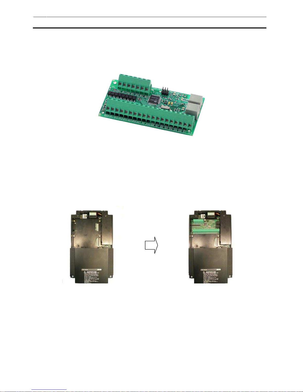
7.-Next figure shows how to install the option board to option port 1 or 2 of the inverter. There are four
holes on the corners of the option board. Align the board with the port connection in the proper
orientation (to the left, when facing the inverter as show). Then align the top two holes with the two
screw holes, and the bottom two holes with the two guide posts. Insert the board fully into the
connector. Secure the board with the two screws supplied.
8.-Then wire expansion I/O board 3G3AX-EIO21-RE. Wiring example:
9.- Power up the inverter. Confirm in the expansion I/O board that the RUN and PWR leds are
activated. It will indicate expansion I/O board is working.
10.- Program with CX-Drive and Drive Programming tool your program using the exclusively
dedicated user parameters for your application purpose.
11.- Set the inverter parameter A017 to value 1 or 2 to run the Drive Programming program. Now,
Drive Prorgamming program is linked and working with the expansion I/O module 3G3AX-EIO21-RE.
(*) All new option boards will not work with this new setting (Profibus, devicenet, componet, ethercat).
Page 6

Expansion I/O Board 3G3AX-EIO21-RE
Expansion IO Board 3G3AX-EIO21-RE
Page 6 of 7
DRAFT V0.90
4 DRIVE PROGRAMMING
4.1 Dedicated User Parameters
Using Expansion I/O Board 3G3AX-EIO21-RE on 3G3RX inveter some Drive Programming internal
user parameters are exclusively dedicated. Refer to the next table:
Parameters Description Range
U(00) To read the 8 expanded digital input status
0 – 255
[from bit 0(IX0) to bit 7(IX7)]
U(01) To write into the 8 expanded digital outputs
0 – 255
[from bit 0(QX0) to bit 7(QX7)]
U(02) To read the expanded Analog Input IW0
0 – 255
[0 vdc – 10 vdc]
U(03) To read the expanded Analog Input IW1
0 – 255
[0 vdc – 10 vdc]
U(04) To read the expanded Analog Input IW2
0 – 255
[0 vdc – 10 vdc]
U(05) To read the expanded Analog Input IW3
0 – 255
[0 vdc – 10 vdc]
U(06) To write the expande Analog Output QW value
0 – 255
[0 vdc – 10 vdc]
4.2 Dedicated User Parameters U(00) and U(01) bit detail description
· U(00): stores the status of the 8 expanded Digital Inputs. The next table indicates the
correspondence between each expanded digital input and U(00) parameter bit:
U(00)
Bit 15
Bit 14
Bit 13
Bit 12
Bit 11
Bit 10
Bit 09
Bit 08
Bit 07
Bit 06
Bit 05
Bit 04
Bit 03
Bit 02
Bit 01
Bit 00
0 0 0 0 0 0 0 0
IX7 IX6 IX5 IX4 IX3 IX2 IX1 IX0
· U(01): to write into the 8 expanded Digital Outputs. The next table indicates the correspondence
between each expanded digital output and U(01) parameter bit:
U(01)
Bit 15
Bit 14
Bit 13
Bit 12
Bit 11
Bit 10
Bit 09
Bit 08
Bit 07
Bit 06
Bit 05
Bit 04
Bit 03
Bit 02
Bit 01
Bit 00
0 0 0 0 0 0 0 0
QX7 QX6 QX5 QX4 QX3 QX2 QX1 QX0
Page 7

Expansion I/O Board 3G3AX-EIO21-RE
Expansion IO Board 3G3AX-EIO21-RE
Page 7 of 7
DRAFT V0.90
4.3 Drive Programming example
 Loading...