

Page 1

Cat. No. O008-E1-04
USER’S MANUAL
3F88L-160/162 Cam Positioner
Page 2

Thank you for choosing this 3F88L-160/162 Cam Positioner. Proper use and handling of
the product will ensure proper product performance, will lengthen product life, and may
prevent possible accidents.
Please read this manual thoroughly and handle and operate the product with care.
1. To ensure safe and proper use of the OMRON Cam Positioners, please read this USER’S
MANUAL (Cat. No. O008-E1) to gain sufficient knowledge of the devices, safety information,
and precautions before actual use.
2. The products are illustrated without covers and shieldings for closer look in this USER’S
MANUAL. For actual use of the products, make sure to use the covers and shieldings as specified.
3. This USER’S MANUAL and other related user’s manuals are to be delivered to the actual end
users of the products.
4. Please keep this manual close at hand for future reference.
5. If the product has been left unused for a long time, please inquire at our sales representative.
NOTICE
1. This manual describes the functions of the product and relations with other products. You
should assume that anything not described in this manual is not possible.
2. Although care has been given in documenting the product, please contact your OMRON
representative if you have any suggestions on improving this manual.
3. The product contains potentially dangerous parts under the cover. Do not attempt to open
the cover under any circumstances. Doing so may result in injury or death and may damage
the product. Never attempt to repair or disassemble the product.
4. We recommend that you add the following precautions to any instruction manuals you prepare for the system into which the product is being installed.
S Precautions on the dangers of high-voltage equipment.
S Precautions on touching the terminals of the product even after power has been turned off. (These
terminals are live even with the power turned off.)
5. Specifications and functions may be changed without notice in order to improve product
performance.
Items to Check Before Unpacking
1. Check the following items before removing the 3F88L-160/162 Cam Positioner from the
package:
S Has the correct product been delivered (i.e., the correct model number and specifications)?
S Has the product been damaged in shipping?
S Are any screws or bolts loose?
S Have all accessories been correctly delivered together with or attached to the product? The acces-
sory for the 3F88L-160/162 Cam Positioner is the Safety Precautions only.
Mounting screws and other necessary parts must be provided by the customer. Should there
be any problems with this product, contact your nearest OMRON sales representative.
2. Check the following items before removing the 3F88L-RS17/17T/15/15W Resolver from
the package:
S Has the correct product been delivered (i.e., the correct model number and specifications)?
S Has the product been damaged in shipping?
S Are any screws or bolts loose?
S Have all accessories been correctly delivered together with or attached to the product? The acces-
sories for the 3F88L-RS17/17T are one 3F88L-RL10 Coupling and one copy of the user’s manual.
The accessories for the 3F88L-RS15/15W are one 3F88L-RL6 Coupling and three mounting claws.
Should there be any problems with this product, contact your nearest OMRON sales representative.
Page 3

Notice:
OMRON products are manufactured for use according to proper procedures by a qualified
operator and only for the purposes described in this manual.
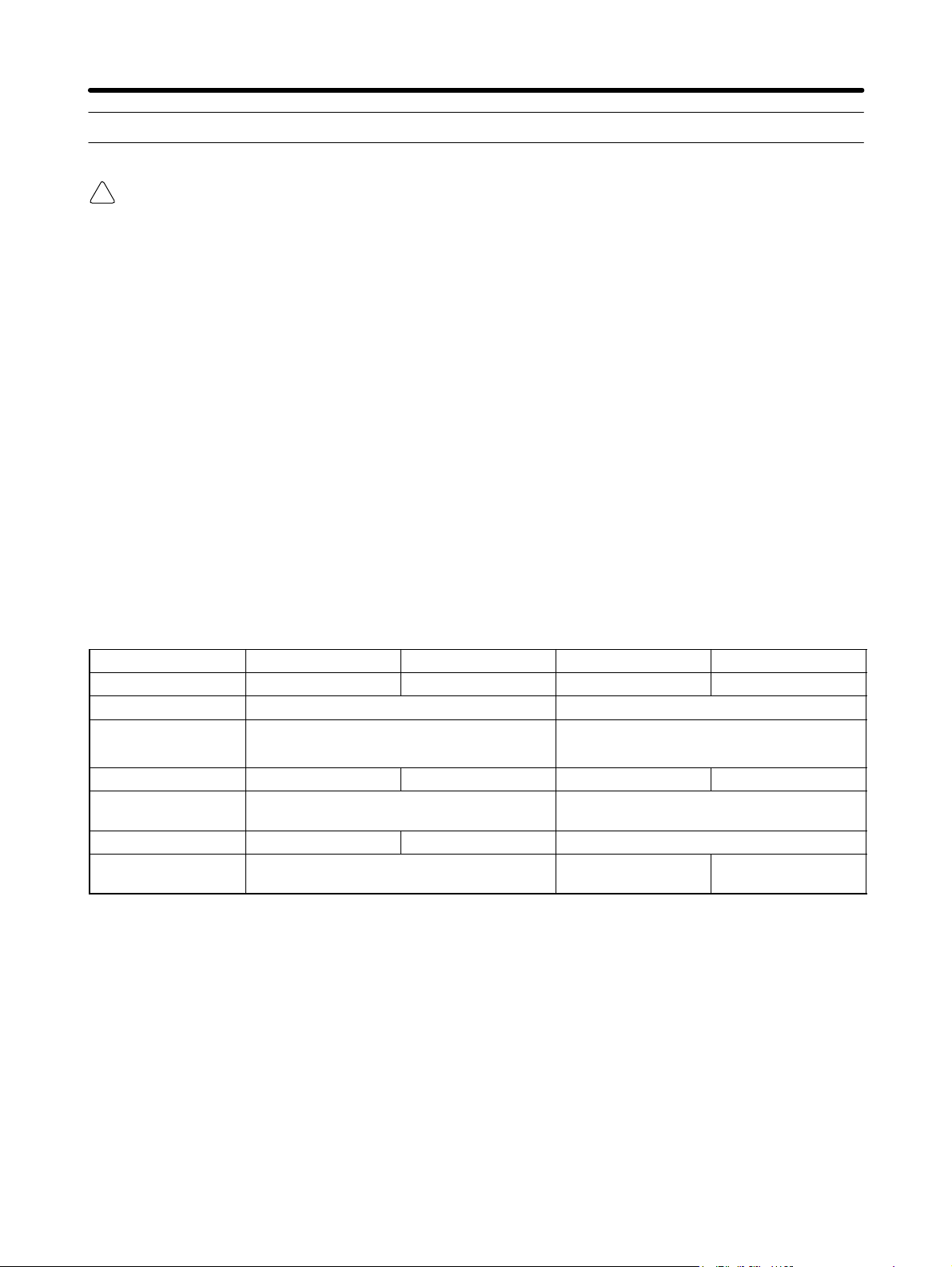
The following conventions are used to indicate and classify precautions in this manual. Always heed the information provided with them. Failure to heed precautions can result in injury to people or damage to property.
!
DANGER Indicates an imminently hazardous situation which, if not avoided, will result in death
or serious injury. Additionally, there may be severe property damage.
WARNING Indicates a potentially hazardous situation which, if not avoided, could result in death
!
or serious injury. Additionally, there may be severe property damage.
Caution Indicates a potentially hazardous situation which, if not avoided, may result in minor
!
or moderate injury, or property damage.
OMRON Product References
All OMRON products are capitalized in this manual. The word “Unit” is also capitalized when
it refers to an OMRON product, regardless of whether or not it appears in the proper name
of the product.
The abbreviation “Ch,” which appears in some displays and on some OMRON products, often means “word” and is abbreviated “Wd” in documentation in this sense.
The abbreviation “PC” means Programmable Controller and is not used as an abbreviation
for anything else.
Visual Aids
The following headings appear in the left column of the manual to help you locate different
types of information.
Note Indicates information of particular interest for efficient and convenient operation of the product.
OMRON, 1999
All rights reserved. No part of this publication may be reproduced, stored in a retrieval system, or transmitted,
in any form, or by any means, mechanical, electronic, photocopying, recording, or otherwise, without the prior
written permission of OMRON.
No patent liability is assumed with respect to the use of the information contained herein. Moreover, because
OMRON is constantly striving to improve its high-quality products, the information contained in this manual
is subject to change without notice. Every precaution has been taken in the preparation of this manual. Nevertheless, OMRON assumes no responsibility for errors or omissions. Neither is any liability assumed for damages resulting from the use of the information contained in this publication.
Page 4

Intended Audience
This manual is intended for the following personnel, who must also have knowledge of electrical systems (an electrical engineer or the equivalent).
S Personnel in charge of installing FA systems.
S Personnel in charge of designing FA systems.
S Personnel in charge of managing FA systems and facilities.
General Precautions
The user must operate the product according to the performance specifications described in the operation manuals.
Before using the product under conditions which are not described in the manual or applying the
product to nuclear control systems, railroad systems, aviation systems, vehicles, combustion systems, medical equipment, amusement machines, safety equipment, and other systems, machines,
and equipment that may have a serious influence on lives and property if used improperly, consult
your OMRON representative.
Make sure that the ratings and performance characteristics of the product are sufficient for the systems, machines, and equipment, and be sure to provide the systems, machines, and equipment with
double safety mechanisms.
This manual provides information for programming and operating the Unit. Be sure to read this manual before attempting to use the Unit and keep this manual close at hand for reference during operation.
WARNING It is extremely important that a PC and all PC Units be used for the specified purpose
!
and under the specified conditions, especially in applications that can directly or
indirectly affect human life. You must consult with your OMRON representative
before applying a PC System to the above-mentioned applications.
Safety Precautions
General Warnings
WARNING Do not attempt to disassemble the Unit while power is being supplied. Doing so may
!
result in electrical shock.
WARNING Do not touch any of the terminals while power is being supplied. Doing so may result
!
in electrical shock.
WARNING Take safety measures outside the Cam Positioner to ensure safety for the entire
!
system in the event of Cam Positioner failure or error caused by external factors of
the Cam Positioner.
Faulty operations may result in serious accidents.
S Emergency stop circuits, interlock circuits, limit circuits, and similar safety mea-
sures must be included in control circuits outside the Cam Positioner.
S The Cam Positioner turns OFF all outputs when its self-diagnostic function detects
an error (ERROR is OFF), when TRIG input turns ON, or when RESET input turns
ON. Take safety measures outside the Cam Positioner to ensure safety for the entire system in such an event.
S The Cam Positioner output may remain ON or OFF due to damage to an output
transistor or for some other reason. Take safety measures outside the Cam Positioner to ensure safety for the entire system in such an event.
Page 5

General Precautions
Caution Fail-safe measures must be taken by the customer to ensure safety in the event of
!
incorrect, missing, or abnormal signals caused by broken signal lines, momentary
power interruptions, or other causes.
Caution Always use the power supply voltages specified in the operation manuals.
!
Caution Take appropriate measures to ensure that the specified power with the rated voltage
!
and frequency is supplied. Be particularly careful in locations where the power supply is unstable.
Caution Install external breakers and take other safety measures against short-circuiting in
!
external wiring.
Caution Disconnect the functional ground terminal from the protective ground terminal when
!
performing insulation resistance or withstand voltage tests
Caution Always connect to a ground of 100 Ω or less when installing the Unit.
!
Caution Do not attempt to disassemble, repair, or modify the Unit.
!
Caution Leave the label attached to the Unit when wiring.
!
Caution Remove the label after the completion of wiring to ensure proper heat dissipation.
!
Caution Use crimp terminals for wiring. Do not connect bare stranded wires directly to termi-
!
nals.
Caution Thoroughly check all wiring before turning ON the power supply.
!
Caution Wire all connections correctly.
!
Caution Do not place objects on top of the cables or other wiring lines.
!
Caution Do not pull on the cables or bend the cables beyond their natural limit.
!
Caution Before touching a Unit, be sure to first touch a grounded metallic object in order to
!
discharge any static built-up.
Caution Be sure that all the mounting screws, terminal screws, and cable connector screws
!
are tightened to the torque specified in the operation manual. For DIN track mounting, push the Cam Positioner forward until the lock snaps into place.
Page 6

Caution Be sure that cables and other items with locking devices are properly locked into
!
place.
Caution Always turn OFF the power supply to the Unit before attempting any of the following.
!
S Assembling the Unit.
S Setting switches.
S Connecting cables or wiring the system.
S Connecting or disconnecting the connectors.
Caution Thoroughly check the newly created cam programs, parameter settings, and switch
!
settings for proper execution before actually running them.
Caution Confirm that no adverse effect will occur in the system before attempting any of the
!
following.
S Switching the operating mode of the Unit
S Origin compensation
S Switching the execution bank
Caution When installing the Unit, adjust the origin before starting operation.
!
Caution Be sure that the number of resolver rotations is always within the allowable range.
!
Caution When replacing the Unit, transfer all the parameters and cam programs from the old
!
Unit to the new Unit before restarting operation.
Caution Do not apply voltages to the input terminal in excess of the rated input voltage.
!
Caution Do not apply voltages or connect loads to the output terminal or cam output connec-
!
tor in excess of the maximum switching capacity.
Caution Do not touch the terminals for one minute after the power is turned OFF.
!
Page 7

Installation Precautions
Caution Install the Unit properly as specified in the operation manual.
!
Caution Do not install the Unit in the following locations.
!
S Locations subject to direct sunlight.
S Locations subject to temperatures or humidity outside the range specified in the
specifications.
S Locations subject to condensation as the result of severe changes in temperature.
S Locations subject to corrosive or flammable gases.
S Locations subject to dust (especially iron dust) or salts.
S Locations subject to exposure to water, oil, or chemicals.
S Locations subject to shock or vibration.
Caution Take appropriate and sufficient countermeasures when installing the Unit in the fol-
!
lowing locations.
S Locations subject to static electricity or other forms of noise.
S Locations subject to strong electromagnetic fields and magnetic fields.
S Locations subject to possible exposure to radioactivity.
S Locations close to power supplies.
Conformance to EC Directives
H Applicable Directives
S EMC Directives
S Low Voltage Directive
Concepts
EMC Directives
EMC Directives stipulate that the system must comply with both EMS and EMI standards
(see the following note). Because OMRON devices are designed for installation in various
equipment or machines, they comply with the relevant EMC standards so that the equipment or machines can easily comply with the EMC standards. However, the systems used
by customers are diverse, and EMC-related performance of the OMRON devices that comply with EC Directives will vary depending on the configuration, wiring, and other conditions
of the equipment or control panel in which the OMRON devices are installed. The customer
must, therefore, perform final checks to confirm that devices and the overall machine conform to EMC standards.
Note Applicable EMC (Electromagnetic Compatibility) standards are as follows:
EMS (Electromagnetic Susceptibility): EN61131-2
EMI (Electromagnetic Interference): EN61000-6-4
(Radiated emission: 10-m regulations)
Low Voltage Directive
Always ensure that devices operating at voltages of 50 to 1,000 V AC or 75 to 1,500 V DC
meet the required safety standards (EN61131-2).
Page 8

Conformance to EC Directives
The 3F88L-160/162 Cam Positioner complies with EC Directives. To ensure that the system in which
the 3F88L-160/162 is installed complies with EC Directives, the following precautions must be observed.
1. The 3F88L-160/162 is defined as an in-panel device according to the Low-voltage Directive.
The 3F88L-160/162 must, therefore, be installed within a control panel.
2. Reinforced insulation or double insulation must be used for the DC power supplies used as
I/O power supplies.
3. The 3F88L-160/162 conforms to the Common Emission Standard (EN61000-6-4) in relation to EMI. However, the radiated emission (10-m regulations) may vary depending on the
configuration of the control panel, connected devices, wiring, and other conditions. The user
must, therefore, confirm that devices and the overall machinery conform to EC Directives.
Page 9

Terms and Conditions Agreement
Warranty, Limitations of Liability
Warranties
Exclusive
Warranty
Limitations OMRON MAKES NO WARRANTY OR REPRESENTATION, EXPRESS OR
Buyer Remedy Omron’s sole obligation hereunder shall be, at Omron’s election, to (i) replace (in the
Omron’s exclusive warranty is that the Products will be free from defects in materials
and workmanship for a period of twelve months from the date of sale by Omron (or
such other period expressed in writing by Omron). Omron disclaims all other warranties, express or implied.
IMPLIED, ABOUT NON-INFRINGEMENT, MERCHANTABILITY OR FITNESS FOR
A PARTICULAR PURPOSE OF THE PRODUCTS. BUYER ACKNOWLEDGES
THAT IT ALONE HAS DETERMINED THAT THE PRODUCTS WILL SUITABLY
MEET THE REQUIREMENTS OF THEIR INTENDED USE.
Omron further disclaims all warranties and responsibility of any type for claims or
expenses based on infringement by the Products or otherwise of any intellectual
property right.
form originally shipped with Buyer responsible for labor charges for removal or
replacement thereof) the non-complying Product, (ii) repair the non-complying Product, or (iii) repay or credit Buyer an amount equal to the purchase price of the noncomplying Product; provided that in no event shall Omron be responsible for warranty, repair, indemnity or any other claims or expenses regarding the Products
unless Omron’s analysis confirms that the Products were properly handled, stored,
installed and maintained and not subject to contamination, abuse, misuse or inappropriate modification. Return of any Products by Buyer must be approved in writing
by Omron before shipment. Omron Companies shall not be liable for the suitability
or unsuitability or the results from the use of Products in combination with any electrical or electronic components, circuits, system assemblies or any other materials
or substances or environments. Any advice, recommendations or information given
orally or in writing, are not to be construed as an amendment or addition to the
above warranty.
Limitation on
Liability; Etc
See http://www.omron.com/global/ or contact your Omron representative for published information.
OMRON COMPANIES SHALL NOT BE LIABLE FOR SPECIAL, INDIRECT, INCIDENTAL, OR CONSEQUENTIAL DAMAGES, LOSS OF PROFITS OR PRODUCTION OR COMMERCIAL LOSS IN ANY WAY CONNECTED WITH THE
PRODUCTS, WHETHER SUCH CLAIM IS BASED IN CONTRACT, WARRANTY,
NEGLIGENCE OR STRICT LIABILITY.
Further, in no event shall liability of Omron Companies exceed the individual price of
the Product on which liability is asserted.
Page 10

Application Considerations
Suitability of
Use
Programmable
Products
Disclaimers
Performance
Data
Omron Companies shall not be responsible for conformity with any standards,
codes or regulations which apply to the combination of the Product in the Buyer’s
application or use of the Product. At Buyer’s request, Omron will provide applicable
third party certification documents identifying ratings and limitations of use which
apply to the Product. This information by itself is not sufficient for a complete determination of the suitability of the Product in combination with the end product,
machine, system, or other application or use. Buyer shall be solely responsible for
determining appropriateness of the particular Product with respect to Buyer’s application, product or system. Buyer shall take application responsibility in all cases.
NEVER USE THE PRODUCT FOR AN APPLICATION INVOLVING SERIOUS RISK
TO LIFE OR PROPERTY WITHOUT ENSURING THAT THE SYSTEM AS A
WHOLE HAS BEEN DESIGNED TO ADDRESS THE RISKS, AND THAT THE
OMRON PRODUCT(S) IS PROPERLY RATED AND INSTALLED FOR THE
INTENDED USE WITHIN THE OVERALL EQUIPMENT OR SYSTEM.
Omron Companies shall not be responsible for the user’s programming of a programmable Product, or any consequence thereof.
Data presented in Omron Company websites, catalogs and other materials is provided as a guide for the user in determining suitability and does not constitute a warranty. It may represent the result of Omron’s test conditions, and the user must
correlate it to actual application requirements. Actual performance is subject to the
Omron’s Warranty and Limitations of Liability.
Change in
Specifications
Errors and
Omissions
Product specifications and accessories may be changed at any time based on
improvements and other reasons. It is our practice to change part numbers when
published ratings or features are changed, or when significant construction changes
are made. However, some specifications of the Product may be changed without
any notice. When in doubt, special part numbers may be assigned to fix or establish
key specifications for your application. Please consult with your Omron’s representative at any time to confirm actual specifications of purchased Product.
Information presented by Omron Companies has been checked and is believed to
be accurate; however, no responsibility is assumed for clerical, typographical or
proofreading errors or omissions.
Page 11

USER’S MANUAL
3F88L-160/162 Cam Positioner
Page 12

Table of Contents
Chapter 1. Outline 1-1. . . . . . . . . . . . . . . . . . . . . . . . . . . . . . . . . . . . . . . . . .
1-1 Functions 1-2. . . . . . . . . . . . . . . . . . . . . . . . . . . . . . . . . . . . . . . . . . . . . . . . . . . . . . . . . . . . . . . . . .
1-1-1 Basic Operation 1-2. . . . . . . . . . . . . . . . . . . . . . . . . . . . . . . . . . . . . . . . . . . . . . . . . . . . . . .
1-1-2 Resolution 1-2. . . . . . . . . . . . . . . . . . . . . . . . . . . . . . . . . . . . . . . . . . . . . . . . . . . . . . . . . . .
1-1-3 Modes 1-3. . . . . . . . . . . . . . . . . . . . . . . . . . . . . . . . . . . . . . . . . . . . . . . . . . . . . . . . . . . . . .
1-1-4 Selecting the Function Level 1-3. . . . . . . . . . . . . . . . . . . . . . . . . . . . . . . . . . . . . . . . . . . .
1-1-5 Basic Functions 1-3. . . . . . . . . . . . . . . . . . . . . . . . . . . . . . . . . . . . . . . . . . . . . . . . . . . . . . .
1-1-6 Initial Settings Functions 1-4. . . . . . . . . . . . . . . . . . . . . . . . . . . . . . . . . . . . . . . . . . . . . . .
1-1-7 Applied Functions 1-4. . . . . . . . . . . . . . . . . . . . . . . . . . . . . . . . . . . . . . . . . . . . . . . . . . . . .
1-2 System Configuration 1-6. . . . . . . . . . . . . . . . . . . . . . . . . . . . . . . . . . . . . . . . . . . . . . . . . . . . . . . .
1-3 Name and Function of Each Part 1-7. . . . . . . . . . . . . . . . . . . . . . . . . . . . . . . . . . . . . . . . . . . . . . . .
1-3-1 Display Section 1-8. . . . . . . . . . . . . . . . . . . . . . . . . . . . . . . . . . . . . . . . . . . . . . . . . . . . . . .
1-3-2 Switches 1-8. . . . . . . . . . . . . . . . . . . . . . . . . . . . . . . . . . . . . . . . . . . . . . . . . . . . . . . . . . . .
1-3-3 Operation Keys 1-9. . . . . . . . . . . . . . . . . . . . . . . . . . . . . . . . . . . . . . . . . . . . . . . . . . . . . . .
1-3-4 Terminal Block and Connectors 1-9. . . . . . . . . . . . . . . . . . . . . . . . . . . . . . . . . . . . . . . . . .
1-4 Glossary 1-10. . . . . . . . . . . . . . . . . . . . . . . . . . . . . . . . . . . . . . . . . . . . . . . . . . . . . . . . . . . . . . . . . . .
1-5 Operation Procedure 1-11. . . . . . . . . . . . . . . . . . . . . . . . . . . . . . . . . . . . . . . . . . . . . . . . . . . . . . . . .
1-5-1 Before Operation 1-11. . . . . . . . . . . . . . . . . . . . . . . . . . . . . . . . . . . . . . . . . . . . . . . . . . . . . .
Chapter 2. Design 2-1. . . . . . . . . . . . . . . . . . . . . . . . . . . . . . . . . . . . . . . . . .
2-1 System Design 2-2. . . . . . . . . . . . . . . . . . . . . . . . . . . . . . . . . . . . . . . . . . . . . . . . . . . . . . . . . . . . . .
2-1-1 Selecting the Resolver 2-2. . . . . . . . . . . . . . . . . . . . . . . . . . . . . . . . . . . . . . . . . . . . . . . . .
2-1-2 Selecting the Output Device 2-4. . . . . . . . . . . . . . . . . . . . . . . . . . . . . . . . . . . . . . . . . . . . .
2-2 Installation 2-6. . . . . . . . . . . . . . . . . . . . . . . . . . . . . . . . . . . . . . . . . . . . . . . . . . . . . . . . . . . . . . . . .
2-2-1 External Dimensions 2-6. . . . . . . . . . . . . . . . . . . . . . . . . . . . . . . . . . . . . . . . . . . . . . . . . . .
2-2-2 Installation Environment 2-8. . . . . . . . . . . . . . . . . . . . . . . . . . . . . . . . . . . . . . . . . . . . . . .
2-2-3 Mounting the Resolver 2-9. . . . . . . . . . . . . . . . . . . . . . . . . . . . . . . . . . . . . . . . . . . . . . . . .
2-3 Wiring 2-13. . . . . . . . . . . . . . . . . . . . . . . . . . . . . . . . . . . . . . . . . . . . . . . . . . . . . . . . . . . . . . . . . . . .
2-3-1 System Connection Diagram 2-13. . . . . . . . . . . . . . . . . . . . . . . . . . . . . . . . . . . . . . . . . . . .
2-3-2 Standard Wiring Method 2-14. . . . . . . . . . . . . . . . . . . . . . . . . . . . . . . . . . . . . . . . . . . . . . . .
2-3-3 Terminal Block Wiring 2-16. . . . . . . . . . . . . . . . . . . . . . . . . . . . . . . . . . . . . . . . . . . . . . . . .
2-3-4 Resolver Wiring 2-21. . . . . . . . . . . . . . . . . . . . . . . . . . . . . . . . . . . . . . . . . . . . . . . . . . . . . .
2-3-5 Cam Output Wiring 2-22. . . . . . . . . . . . . . . . . . . . . . . . . . . . . . . . . . . . . . . . . . . . . . . . . . . .
2-3-6 Connecting a Display Unit 2-25. . . . . . . . . . . . . . . . . . . . . . . . . . . . . . . . . . . . . . . . . . . . . .
Chapter 3. Operation 3-1. . . . . . . . . . . . . . . . . . . . . . . . . . . . . . . . . . . . . . .
3-1 Nomenclature of Display and Operation Sections 3-2. . . . . . . . . . . . . . . . . . . . . . . . . . . . . . . . . .
3-2 Modes, Functions, and Display 3-4. . . . . . . . . . . . . . . . . . . . . . . . . . . . . . . . . . . . . . . . . . . . . . . . .
3-3 Operation Procedure 3-12. . . . . . . . . . . . . . . . . . . . . . . . . . . . . . . . . . . . . . . . . . . . . . . . . . . . . . . . .
3-3-1 Before Operation 3-12. . . . . . . . . . . . . . . . . . . . . . . . . . . . . . . . . . . . . . . . . . . . . . . . . . . . . .
3-4 Selecting Function Levels 3-14. . . . . . . . . . . . . . . . . . . . . . . . . . . . . . . . . . . . . . . . . . . . . . . . . . . . .
3-5 Basic Operation 3-20. . . . . . . . . . . . . . . . . . . . . . . . . . . . . . . . . . . . . . . . . . . . . . . . . . . . . . . . . . . . .
3-5-1 Function Level Selection Setting (SET Mode) 3-20. . . . . . . . . . . . . . . . . . . . . . . . . . . . . .
3-5-2 Initial Settings 3-21. . . . . . . . . . . . . . . . . . . . . . . . . . . . . . . . . . . . . . . . . . . . . . . . . . . . . . . .
3-5-3 Cam Program Creating and Checking (PRGM Mode/SET Mode) 3-24. . . . . . . . . . . . . . .
3-5-4 Resolver and Machinery Connection 3-37. . . . . . . . . . . . . . . . . . . . . . . . . . . . . . . . . . . . . .
3-5-5 Origin Compensation 3-37. . . . . . . . . . . . . . . . . . . . . . . . . . . . . . . . . . . . . . . . . . . . . . . . . .
3-5-6 Start Operation (RUN Mode) 3-38. . . . . . . . . . . . . . . . . . . . . . . . . . . . . . . . . . . . . . . . . . . .
3-5-7 I/O Monitor Function (RUN Mode) 3-40. . . . . . . . . . . . . . . . . . . . . . . . . . . . . . . . . . . . . . .
3-5-8 Control I/O Signals 3-42. . . . . . . . . . . . . . . . . . . . . . . . . . . . . . . . . . . . . . . . . . . . . . . . . . . .
Page 13

Table of Contents
3-6 Applied Functions 3-44. . . . . . . . . . . . . . . . . . . . . . . . . . . . . . . . . . . . . . . . . . . . . . . . . . . . . . . . . . .
3-6-1 Function Level Selection Setting (SET Mode) 3-44. . . . . . . . . . . . . . . . . . . . . . . . . . . . . .
3-6-2 Parameter List (SET Mode) 3-45. . . . . . . . . . . . . . . . . . . . . . . . . . . . . . . . . . . . . . . . . . . . .
3-6-3 Parameter Explanation and Operation 3-49. . . . . . . . . . . . . . . . . . . . . . . . . . . . . . . . . . . . .
3-6-4 Origin Compensation and Origin Shift 3-56. . . . . . . . . . . . . . . . . . . . . . . . . . . . . . . . . . . . .
3-6-5 Backlash Compensation 3-60. . . . . . . . . . . . . . . . . . . . . . . . . . . . . . . . . . . . . . . . . . . . . . . .
3-6-6 Advance Angle Compensation 3-62. . . . . . . . . . . . . . . . . . . . . . . . . . . . . . . . . . . . . . . . . . .
3-6-7 Cam Protect 3-69. . . . . . . . . . . . . . . . . . . . . . . . . . . . . . . . . . . . . . . . . . . . . . . . . . . . . . . . . .
3-6-8 One-direction Function 3-75. . . . . . . . . . . . . . . . . . . . . . . . . . . . . . . . . . . . . . . . . . . . . . . . .
3-6-9 Output Hold Function 3-77. . . . . . . . . . . . . . . . . . . . . . . . . . . . . . . . . . . . . . . . . . . . . . . . . .
3-6-10 Present Value Output Function 3-78. . . . . . . . . . . . . . . . . . . . . . . . . . . . . . . . . . . . . . . . . . .
3-6-11 Pulse Output Function 3-80. . . . . . . . . . . . . . . . . . . . . . . . . . . . . . . . . . . . . . . . . . . . . . . . .
3-6-12 Teaching 3-83. . . . . . . . . . . . . . . . . . . . . . . . . . . . . . . . . . . . . . . . . . . . . . . . . . . . . . . . . . . .
3-6-13 Copy Function (Data Transfer) 3-88. . . . . . . . . . . . . . . . . . . . . . . . . . . . . . . . . . . . . . . . . . .
3-6-14 Trial/Adjustment Operation 3-93. . . . . . . . . . . . . . . . . . . . . . . . . . . . . . . . . . . . . . . . . . . . .
Chapter 4. Communications 4-1. . . . . . . . . . . . . . . . . . . . . . . . . . . . . . . . . .
4-1 Overview of CompoWay/F Communications 4-2. . . . . . . . . . . . . . . . . . . . . . . . . . . . . . . . . . . . . .
4-2 Command and Response Frames 4-5. . . . . . . . . . . . . . . . . . . . . . . . . . . . . . . . . . . . . . . . . . . . . . . .
4-2-1 Command Frame 4-5. . . . . . . . . . . . . . . . . . . . . . . . . . . . . . . . . . . . . . . . . . . . . . . . . . . . . .
4-2-2 Response Frame 4-7. . . . . . . . . . . . . . . . . . . . . . . . . . . . . . . . . . . . . . . . . . . . . . . . . . . . . .
4-3 Command Types 4-10. . . . . . . . . . . . . . . . . . . . . . . . . . . . . . . . . . . . . . . . . . . . . . . . . . . . . . . . . . . .
4-3-1 Memory Area Read (RUN) 4-10. . . . . . . . . . . . . . . . . . . . . . . . . . . . . . . . . . . . . . . . . . . . . .
4-3-2 Parameter Area Read/Write (SET) 4-12. . . . . . . . . . . . . . . . . . . . . . . . . . . . . . . . . . . . . . . .
4-3-3 Controller Data Read (RUN, PRGM, SET) 4-19. . . . . . . . . . . . . . . . . . . . . . . . . . . . . . . . .
4-3-4 Unit Attribute Read (RUN, PRGM, SET) 4-20. . . . . . . . . . . . . . . . . . . . . . . . . . . . . . . . . .
4-3-5 Controller Status Read (RUN, PRGM, SET) 4-20. . . . . . . . . . . . . . . . . . . . . . . . . . . . . . . .
4-3-6 Operation Command (RUN) 4-21. . . . . . . . . . . . . . . . . . . . . . . . . . . . . . . . . . . . . . . . . . . . .
4-3-7 Internode Echo Test (RUN, PRGM, SET) 4-22. . . . . . . . . . . . . . . . . . . . . . . . . . . . . . . . . .
4-4 Executing CompoWay/F Commands with Protocol Macros 4-23. . . . . . . . . . . . . . . . . . . . . . . . . .
Chapter 5. Operation 5-1. . . . . . . . . . . . . . . . . . . . . . . . . . . . . . . . . . . . . . .
5-1 Diagnosis using Error Codes 5-2. . . . . . . . . . . . . . . . . . . . . . . . . . . . . . . . . . . . . . . . . . . . . . . . . . .
5-2 CompoWay/F Communications Errors 5-7. . . . . . . . . . . . . . . . . . . . . . . . . . . . . . . . . . . . . . . . . . .
5-3 Troubleshooting 5-9. . . . . . . . . . . . . . . . . . . . . . . . . . . . . . . . . . . . . . . . . . . . . . . . . . . . . . . . . . . . .
5-4 Inspection and Maintenance 5-12. . . . . . . . . . . . . . . . . . . . . . . . . . . . . . . . . . . . . . . . . . . . . . . . . . .
5-5 Cam Positioner Replacement 5-13. . . . . . . . . . . . . . . . . . . . . . . . . . . . . . . . . . . . . . . . . . . . . . . . . .
Chapter 6. Specifications 6-1. . . . . . . . . . . . . . . . . . . . . . . . . . . . . . . . . . . .
6-1 Cam Positioner Specifications 6-2. . . . . . . . . . . . . . . . . . . . . . . . . . . . . . . . . . . . . . . . . . . . . . . . . .
6-2 Resolver Specifications 6-4. . . . . . . . . . . . . . . . . . . . . . . . . . . . . . . . . . . . . . . . . . . . . . . . . . . . . . .
6-3 I/O Block Specifications 6-6. . . . . . . . . . . . . . . . . . . . . . . . . . . . . . . . . . . . . . . . . . . . . . . . . . . . . .
6-4 Display Specifications 6-8. . . . . . . . . . . . . . . . . . . . . . . . . . . . . . . . . . . . . . . . . . . . . . . . . . . . . . . .
Chapter 7. Appendix 7-1. . . . . . . . . . . . . . . . . . . . . . . . . . . . . . . . . . . . . . . .
7-1 Application Examples 7-2. . . . . . . . . . . . . . . . . . . . . . . . . . . . . . . . . . . . . . . . . . . . . . . . . . . . . . . .
7-2 Performance 7-4. . . . . . . . . . . . . . . . . . . . . . . . . . . . . . . . . . . . . . . . . . . . . . . . . . . . . . . . . . . . . . . .
7-3 Resolver Life Expectancy 7-8. . . . . . . . . . . . . . . . . . . . . . . . . . . . . . . . . . . . . . . . . . . . . . . . . . . . .
7-4 Standard Models 7-11. . . . . . . . . . . . . . . . . . . . . . . . . . . . . . . . . . . . . . . . . . . . . . . . . . . . . . . . . . . .
Page 14

Table of Contents
7-5 Displays by Mode 7-12. . . . . . . . . . . . . . . . . . . . . . . . . . . . . . . . . . . . . . . . . . . . . . . . . . . . . . . . . . .
7-6 Error Codes 7-16. . . . . . . . . . . . . . . . . . . . . . . . . . . . . . . . . . . . . . . . . . . . . . . . . . . . . . . . . . . . . . . .
7-7 Cam Programming Sheet 7-21. . . . . . . . . . . . . . . . . . . . . . . . . . . . . . . . . . . . . . . . . . . . . . . . . . . . . .
7-8 Parameter Settings Log Chart 7-22. . . . . . . . . . . . . . . . . . . . . . . . . . . . . . . . . . . . . . . . . . . . . . . . . .
Index I-1. . . . . . . . . . . . . . . . . . . . . . . . . . . . . . . . . . . . . . . . . .
Revision History R-1. . . . . . . . . . . . . . . . . . . . . . . . . . . . . . . . .
Page 15

1
Chapter 1
Outline
1-1 Functions
1-2 System Configuration
1-3 Name and Function of Each Part
1-4 Glossary
1-5 Operation Procedure
Page 16
Outline Chapter 1
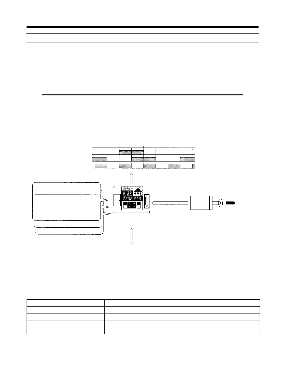
1-1 Functions
The 3F88-L160 and 3F88L-162 Cam Positioners are Units that detect angles through a
Resolver (a sensor that detects absolute angles) and turn output signals ON and OFF at
a preset angle through a cam program.
The 3F88L-160 Cam Positioner has 16 cam output points and the 3F88L-162 Cam Positioner has 32 cam output points.
1-1-1 Basic Operation
• Input a cam program (the ON/OFF pattern for cam outputs) into the Cam Positioner, use the bank
switching signal to select the bank number, and turn ON the operation signal to start operation.
Resolver angle
Cam output 1
Cam output 2
Cam output 3
(Programming example for 360 resolution)
Cam Program (Bank No. 1)
Cam No.
Step ON angle OFF angle
1
1
1
2
1
---
90
315
135
0
---
---
---
2
2
3
---
Cam Program (Bank No. 2)
Cam Program (Bank No. 3)
0° 90° 180° 270° 0°
180
45
225
45
---
1-1-2 Resolution
Cam output
Cam Positioner
Control input
Bank switching signal (Bank numbers 1 to 3)
Operation signal (START)
Resolver
User machine or
device
• The angle resolution can be set to 360 (divisions/revolution) or 720 (divisions/revolution).
• The following table shows how functions and performances are affected by resolution settings.
Function or Characteristic 360 resolution 720 resolution
Angle setting and display units 1° is set and displayed as “1.” 0.5° is set and displayed as “1.”
Permissible Resolver speed 1,600 r/min 800 r/min
No. of cam program steps 180 max. 360 max.
Number of banks 8 4
Note For example, to set the ON angle at 90°, the setting is “90” for a 360 resolution and “180” for a 720
resolution.
1-2
Page 17

Outline Chapter 1
1-1-3 Modes
• The 3F88-L160 and 3F88L-162 Cam Positioners have three modes: RUN, PRGM, and SET. These
are set using the mode selection switch on the front of the Unit. The functions of each mode are outlined below. (Refer to 3-2 Mode, Functions, and Display.)
RUN mode: Operation and compensation.
PRGM mode: Creation, editing, deletion, and trial operation of cam programs.
SET mode: Unit parameters and various compensation value settings, teaching, and communications settings.
1-1-4 Selecting the Function Level
• Three function levels are available to limit Cam Positioner functions. (Refer to 3-4 Selecting Function
Levels.)
Function Level 0 (Monitor Only)
Cam output and monitoring are enabled. Cam programs are write protected and parameter settings
cannot be made. This function level is designed to prevent inadvertent changes to the cam program
or parameters.
Function Level 1 (Basic Operation/Monitor Only)
In addition to the functions available at function level 0, cam programs may be edited. This function
level is used for basic operation.
Function Level 2 (All Functions)
All Cam Positioner functions are enabled. This function level is for using applied functions.
1-1-5 Basic Functions
H Cam Program Write Function
• Cam programs set the angle at which the cam output is turned ON and OFF. Up to 180 steps can be set
and up to 8 banks registered for 360 resolution and up to 360 steps and 4 banks for 720 resolution can
be set for each cam output point. (Refer to 3-5-3 Cam Program Creating and Checking.)
• Cam programs are normally input by using the operation keys on the front of the Unit but settings can
be made from a personal computer by using a special communications protocol (CompoWay/F). (Refer to Chapter 4 Communications.)
Note 1. A step is one ON/OFF combination for one cam.
Note 2. A bank is a program unit made up of cam outputs 1 to 32 for the 3F88L-162 and cam outputs 1
to 16 for the 3F88L-160. By changing the bank, the program that will be operated will change.
H Cam Output
• While START input is ON, this function turns cam outputs ON and OFF in the bank specified at BANK
input according to the ON/OFF angles set for each cam.
H Monitor
• Monitors cam output and control I/O status. (Refer to 3-5-7 I/O Monitor Function.)
1-3
Page 18

Outline Chapter 1
H Data Save
• Saves parameters and cam programs in non-volatile memory (EEPROM). As the data is stored in
non-volatile memory, battery replacement, and other maintenance is not required.
H Program Number Check
• The number of programs and origin compensation angle can be checked. (Refer to 3-5-3 Cam Program Creating and Checking.)
1-1-6 Initial Settings Functions
H Switching Resolution
• Switches between 360 and 720 divisions per Resolver revolution. (Refer to 3-5-2 Initial Settings.)
H Changing Rotation Direction
• Sets the direction of increasing angle to suit the mechanical configuration. (Refer to 3-5-2 Initial Set-
tings.)
1-1-7 Applied Functions
H Origin Compensation
• Sets any angle to 0° according to the mechanical origin. (Refer to 3-6-4 Origin Compensation and
Origin Shift.)
H Origin Shift
• Sets any angle to 0° according to the mechanical origin when the trigger turns ON in RUN mode. (Re-
fer to 3-6-4 Origin Compensation and Origin Shift.)
H Backlash Compensation
• Sets a difference between the detection angles in CW and CCW directions to absorb mechanical
vibration. (Refer to 3-6-5 Backlash Compensation..)
H Advance Angle Compensation
• Advances the cam output angle in proportion to the number of Resolver revolutions. (Refer to 3-6-6
Advance Angle Compensation.)
H Cam Protect
• Protects each bank and cam to prevent the cam ON/OFF data being inadvertently changed or deleted.
H One-direction Function Setting
• Enables cam output in one rotational direction only. (Refer to 3-6-8 One-direction Function.)
1-4
Page 19

Outline Chapter 1
H Output Hold Function
• Holds the immediately preceding cam output status when the user switches to PRGM mode or when
there is an error. (Refer to 3-6-9 Output Hold Function.)
H Present Value Output Function
• Uses the cam output signal and outputs the signal to the Display Unit (M7E, M7F, or other Display
Units.) The present angle or number of revolutions can be displayed on the Display Unit. (Refer to
3-6-10 Present Value Output Function.)
H Pulse Output Function
• Automatically sets data that turns ON and OFF at regular intervals in a desired bank or cam in order to
edit memory contents. (Refer to 3-6-11 Pulse Output Function.)
H Teaching
• The Resolver angle data may be input as cam program settings during manual operation of the
machinery. (Refer to 3-6-12 Teaching.)
H Copy Function
• By making the settings for one Cam Positioner, the cam program, the various compensation values,
and settings in one operation may be copied to another Cam Positioner.
H Trial Operation
• When adjusting the ON/OFF angles to suit the machinery, performs cam output and changes the ON/
OFF angle in real time regardless of the control input signal status. (Refer to 3-6-14 Trial/Adjustment
Operation.)
H Compensation Operation
• When adjusting the ON/OFF angles to suit the machinery, changes the ON/OFF angles in real time
while in operation status (cam output status). (Refer to 3-6-14 Trial/Adjustment Operation.)
H Communications Function
• Has a communications port that conforms to shape B in CompoWay/F. Communications can be used
to read and write cam programs and monitor present angles and number of revolutions. (Refer to
Chapter 4 Communications.)
Note CompoWay/F is a uniform procedure in OMRON serial communications. CompoWay/F has uni-
form frame formats and commands that conform to FINS (Factory Interface Network Service) that
is used in OMRON PCs. It facilitates easier communications between multiple components and
between personal computers and components.
1-5
Page 20
Outline Chapter 1
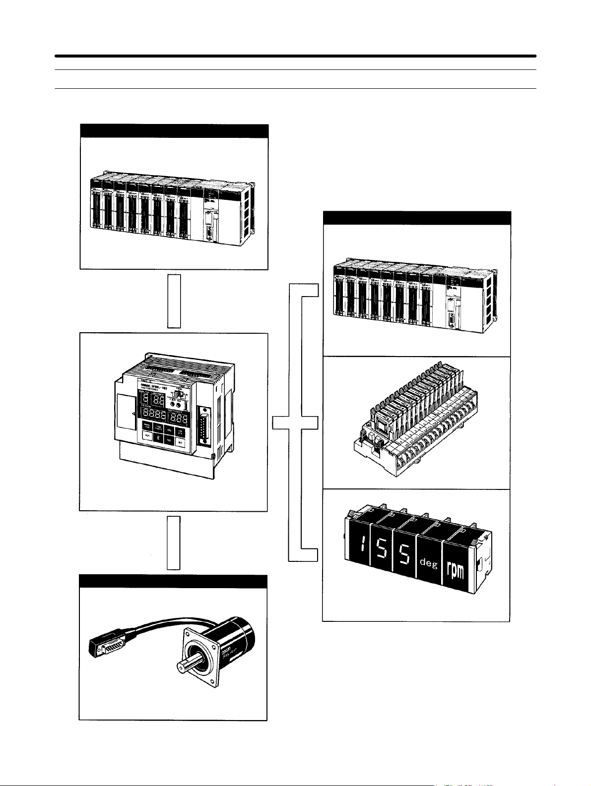
1-2 System Configuration
Control Section
Output Section
SYSMAC CS1-series PC or other PC
Control I/O signal
3F88L-160 or 3F88L-162 Cam Positioner
Cam
output
signal
SYSMAC CS1-series PC or other PC
G7TC-OC16 I/O Block
1-6
Detection Section
3F88L-RS17, 3F88L-RS17T, 3F88L-RS15,
or 3F88L-RS15W Resolver
M7E or M7F Display Unit
Note Refer to 2-3 Wiring or 7-4 Standard
Models for information on various
connection cables.
Page 21
Outline Chapter 1
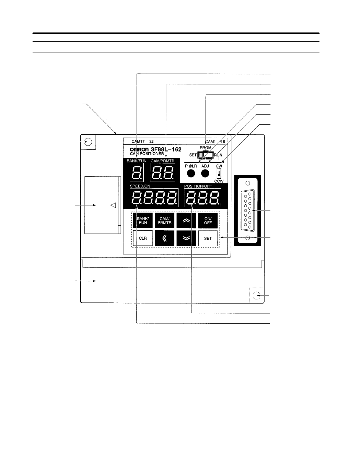
1-3 Name and Function of Each Part
1. Bank/Function
display
2. Cam/Parameter
No. display
5. Mode selection
switch
11. Cam output
connector (top)
Mounting hole
6. P⋅ CLR switch
7. ADJ switch
8. CW/CCW setting
switch
12. Communications port
13. Terminal block
(under the cover)
10. Resolver
connector
9. Operation keys
Mounting hole
4. POSITION/OFF
(Present angle/
OFF angle) display
5. SPEED/ON
(Number of revolutions/ON angle)
display
1-7
Page 22
py
u be d sp ay
g
Outline Chapter 1
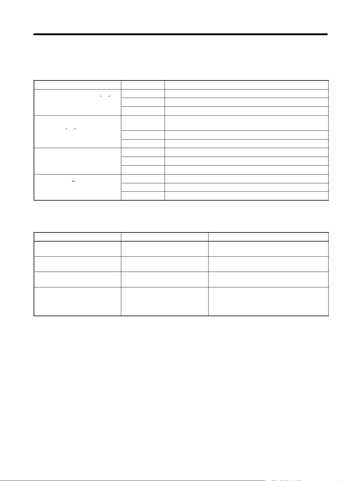
1-3-1 Display Section
• Displays the operation status, error status, and settings data.
• The data displayed will differ depending on the mode.
Name Mode Display
1. Bank and function display
2. Cam and parameter
number display
3. Number of revolutions and
ON angle display
4. Present angle and OFF
angle display
RUN Display the number of the operating bank.
PRGM Display the number of the bank being programmed.
SET Display the number of the function being set.
RUN Displays “ru” when the START signal is ON and is blank
when the START signal is OFF.
PRGM Displays the number of the cam being programmed.
SET (Different for different settings functions.)
RUN Displays the number of revolutions or an error message.
PRGM Displays the ON angle or an error message.
SET (Differs for different settings functions.)
RUN Displays the present angle.
PRGM Displays the OFF angle.
SET (Different for different settings functions.)
1-3-2 Switches
Name Mode Function
5. Mode selection switch --- Switches between the three operation
modes: RUN, PRGM, and SET.
6. P ⋅ CLR switch PRGM Deletes all cam programs in the Cam
Positioner.
7. ADJ switch SET Adjusts the compensation by executing
origin compensation.
8. CW/CCW setting switch When power is turned ON Changes the rotation direction. The direction of increasing angle is set to either CW
(clockwise) or CCW (counterclockwise)
when viewed from the Resolver axle side.
1-8
Page 23
Outline Chapter 1
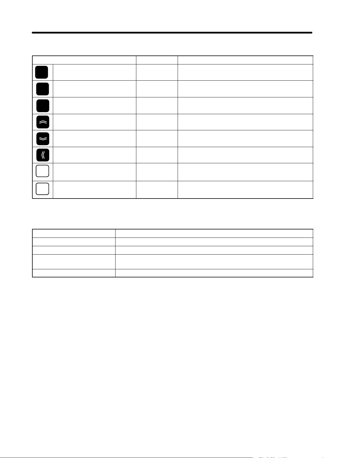
1-3-3 Operation Keys
Name Mode Function
BANK/
FUN
Bank/Function Key PRGM/SET Increases bank and function numbers.
CAM/
PRMTR
Cam/Parameter Key --- Increases cam and parameter numbers.
ON/OFF Switching Key --- Switches between ON and OFF angles.
ON/
OFF
Up Key --- Increases the numeral that is flashing.
Down Key --- Decreases the numeral that is flashing.
Forward Key --- Changes the digit of the numeral to be set.
Clear Key --- Clears data.
CLR
Set Key --- Saves input data.
SET
1-3-4 Terminal Block and Connectors
Name Function
10. Resolver connector Connects to the Resolver cable connector.
11. Cam output connector Used for cam output.
12. Communications port CompoWay/F communications connector (connects to a personal computer
and other Cam Positioners) (9-pin D-sub connector)
13. Terminal block Power input, control input, and control output terminals.
1-9
Page 24

Outline Chapter 1
1-4 Glossary
Term Meaning
Cam output Cam output consists ON/OFF outputs for the Resolver angle according to
the ON/OFF angles set by the user (the cam program).
Cam program A cam program consists ON/OFF angle data set by the user.
Cam protect The cam data protect function protects the cam ON/OFF data from being
inadvertently changed or deleted.
Compensation operation When in RUN mode, this function can be used to adjust the cam output ON
and OFF angles by using the operation keys in order to check mechanical
operation.
Origin compensation When in SET mode, the mechanical origin and the Resolver origin can be
aligned by pressing the ADJ switch on the front of the Cam Positioner.
Origin shift When in RUN mode, this function can be used to temporarily shift the
displayed angle to the origin by shorting the TRIG terminal with the 0-V
terminal.
Origin value The origin value is a value set as the origin of the Resolver. This value can
be set to any angle when origin compensation or origin shift has been
performed. The default setting is 0.
Resolver The Resolver is a sensor that detects the absolute angle. One of four
Resolver models (3F88L-RS17, 3F88L-RS17T, 3F88L-RS15, and
3F88L-RS15W) can be selected for 3F88L-160 and 3F88L-162 Cam
Positioners.
Trial operation When in PRGM mode, this function can be used to adjust the cam output
ON and OFF angles by using the operation keys in order to check
mechanical operation.
The greatest difference from compensation operation is the ability to adjust
the ON and OFF angles of any bank or cam number without any external
control signal input during trial operation.
1-10
Page 25

Outline Chapter 1
1-5 Operation Procedure
1-5-1 Before Operation
H Basic Use
• The procedure for using the Cam Positioner at function level 1 (basic operation/monitor only) is outlined below.
Procedure Contents Reference
section
Installation Install the Cam Positioner according to the installation
environment conditions.
Wiring Connect the wiring for the power supply, Resolver, and
peripheral devices.
Power ON Before the power is turned ON:
• Check that the wires and connectors for the Resolver and
peripheral devices have been connected properly.
• Check that the Resolver and the machinery are not connected.
After the power is turned ON:
• Check that there are no error codes displayed (E–**).
• Set the mode selection switch to RUN and check that the
number of revolutions and the present angle display changes
when the Resolver axis is rotated by hand.
Function level selection Select function level 1 (basic operation/monitor only). 3-5-1
Initial settings Set the resolution (SET mode) and rotation direction
(CW/CCW) to suit the application.
Power resetting (OFF to
ON)
Creation and confirmation
of cam programs
Connection between
Resolver and machinery
Execution of origin
compensation
Operation/monitoring Change to RUN mode and check the operation of the
Function level selection If required, set to function level 0 (monitor only) to prevent
Turn ON the power to enable the set parameters.
Create and check cam programs (PRGM mode).
Check the number of programs (SET mode).
Turn OFF the power and connect the Resolver and the
machinery.
Turn ON the power and execute origin compensation (use
the ADJ switch in SET mode).
machinery and monitor the I/O status. Correct the cam
program if required (PRGM mode).
faulty operation.
2-2
2-3
3-5-2
3-5-3
3-5-4
3-5-5
3-5-6
3-4
Note This procedure is applicable when only the basic functions (function level 1) are used. In the
cases outlined below, the applied functions (function level 2) must be used. (Refer to 3-6 Applied
Functions.)
S When setting origin compensation values, using backlash compensation, advance angle com-
pensation, and other compensation functions.
S When executing a trial or compensation operation.
1-11
Page 26

Outline Chapter 1
S When using the teaching function.
S When making pulse output, cam data protect, output hold, one-direction function, and present
value output settings.
H Applied Functions
• The procedure for using the Cam Positioner at function level 2 (all functions) is outlined below.
Procedure Contents Reference
section
Installation Install the Cam Positioner according to the installation
environment conditions.
Wiring Connect the wiring for the power supply, Resolver, and
peripheral devices.
Power ON Before the power is turned ON:
• Check that the wires and connectors for the Resolver and
peripheral devices have been connected properly.
• Check that the Resolver and the machinery are not connected.
After the power is turned ON:
• Check that there are no error codes displayed (E–**).
• Set the mode selection switch to RUN and check that the
number of revolutions and the present angle display changes
when the Resolver axis is rotated by hand.
Function level selection Select function level 2 (all functions). 3-6-1
Initial settings Set the resolution (SET mode) and rotation direction
(CW/CCW) to suit the application.
Power resetting (OFF to
ON)
Parameter settings Make the parameter settings.
Power resetting (OFF to
ON)
Creation and confirmation
of cam programs
Connection between
Resolver and machinery
Execution of origin
compensation
Teaching If required, use the teaching function (SET mode) and create
Trial operation Change to PRGM mode, and, if required, adjust the cam
Operation/monitoring Change to RUN mode and check the operation of the
Origin shift execution If required, turn ON TRIG input and execute origin shift
Compensation operation If required, adjust the cam program while checking the timing
Function level selection If required, set to function level 0 (monitor only) to prevent
Turn ON the power to enable the set parameters.
Turn ON the power to enable the set parameters.
Create and check cam programs (PRGM mode).
Check the number of programs (SET mode).
Turn OFF the power and connect the Resolver and the
machinery.
Turn ON the power and execute origin compensation (use
the ADJ switch in SET mode).
a cam program while operating the machinery manually.
program while checking the timing of the cam output.
machinery and monitor the I/O status. Correct the cam
program if required (PRGM mode).
(RUN mode).
of the cam output.
faulty operation.
2-2
2-3
3-5-2
3-6-2 and 3-6-3
3-5-3
3-5-4
3-5-5
3-6-12
3-6-14
3-5-6
3-6-4
3-6-14
3-4
1-12
Page 27
Design
2-1 System Design
2-2 Installation
2-3 Wiring
2
Chapter 2
Page 28
Design Chapter 2
2-1 System Design
WARNING Take safety measures outside the Cam Positioner to ensure safety for the entire
!
system in the event of Cam Positioner failure or error caused by factors external to
the Cam Positioner.
Faulty operation may result in a serious accident.
S Emergency stop circuits, interlock circuits, limit circuits, and similar safety mea-
sures must be included in control circuits outside the Cam Positioner.
S The Cam Positioner turns OFF all outputs when its self-diagnostic function detects
an error (ERROR is OFF), when TRIG input turns ON, or when RESET input turns
ON. Take safety measures outside the Cam Positioner to ensure safety for the entire system in such an event.
S The Cam Positioner output may remain ON or OFF due to damage to an output
transistor or for some other reason. Take safety measures outside the Cam Positioner to ensure safety for the entire system in such an event.
2-1-1 Selecting the Resolver
There are four Resolver models available. Select the Resolver suitable for the application.
H Resolvers
Type Large-diameter High-torque Connector Lead-wire
Model 3F88L-RS17 3F88L-RS17T 3F88L-RS15 3F88L-RS15W
Axle diameter 10 mm 6 mm
Rated axle load Thrust load: 196 N max.
Radial load: 196 N max.
Total length 101 mm 110 mm 154 mm 97 mm
Attachment
method
Friction torque
Connection to
Cam Positioner
Note High-torque Resolvers have oil seals.
Flange Connected to the servo.
12 mN S m max. 49 to 147 mN S m 2.9 mN S m max.
Shown in diagram A. Shown in diagramB.Shown in diagram
Thrust load: 98N max.
Radial load: 98 N max.
C.
2-2
Page 29
Design Chapter 2
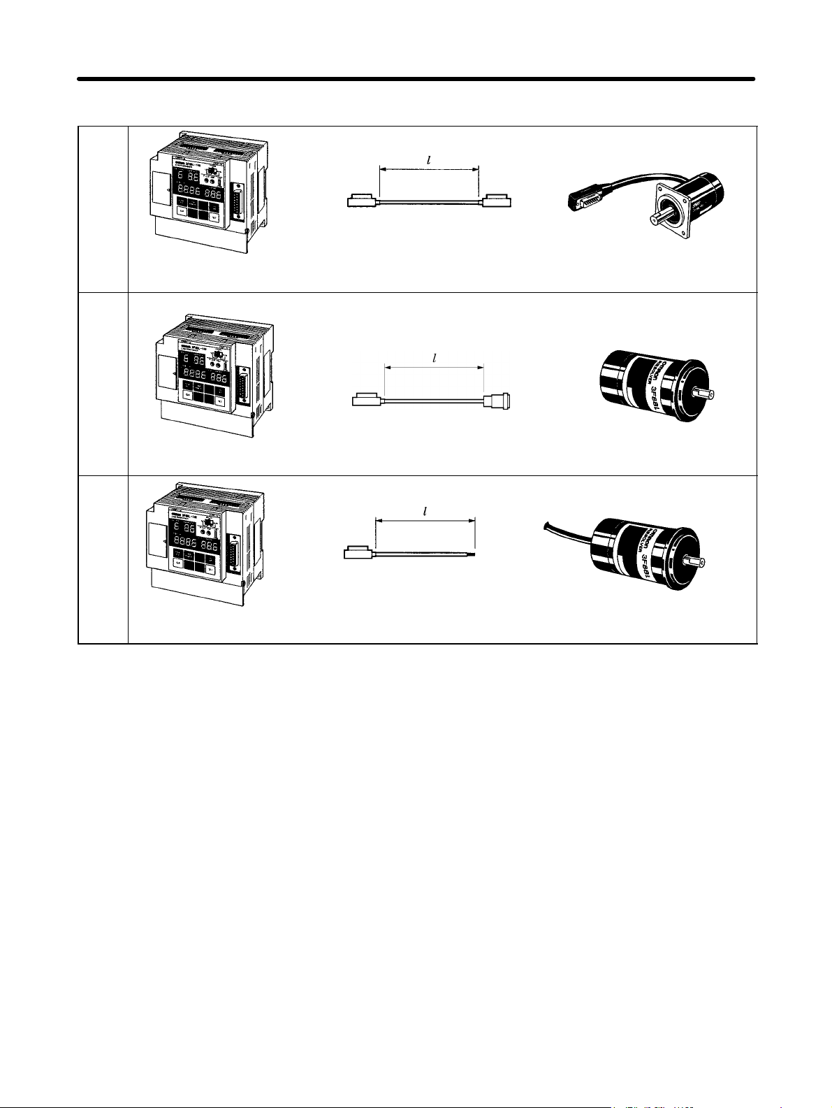
H Cam Positioner and Resolver Configuration
A
3-m Plug-in cable
3F88L-160 or 3F88L-162
Cam Positioner
3F88L-CRjjjC
Resolver Extension Cable
B
3F88L-160 or 3F88L-162
Cam Positioner
3F88L-CRjjjNA
Resolver Cable
C
3F88L-RS17/-RS17T
Resolver
Connector type
3F88L-RS15 Resolver
35-cm Separate wire
plug-in cable
3F88L-160 or 3F88L-162
Cam Positioner
3F88L-CRjjjSA
Resolver Cable
3F88L-RS15S Resolver
Note 1. 3F88-RS17 and 3F88-RS17T Resolvers have 3-m cables. Use the 3F88L-CRjjjC Re-
solver Extension Cable if more cable is required.
Note 2. The jjj in the Extension Cable model number indicates the length of the Extension Cable.
For example, the 3F88L-CR010C Extension Cable is 10 m in length.
Note 3. The distance between the Cam Positioner and the Resolver can be up to 100 m.
2-3
Page 30
Design Chapter 2
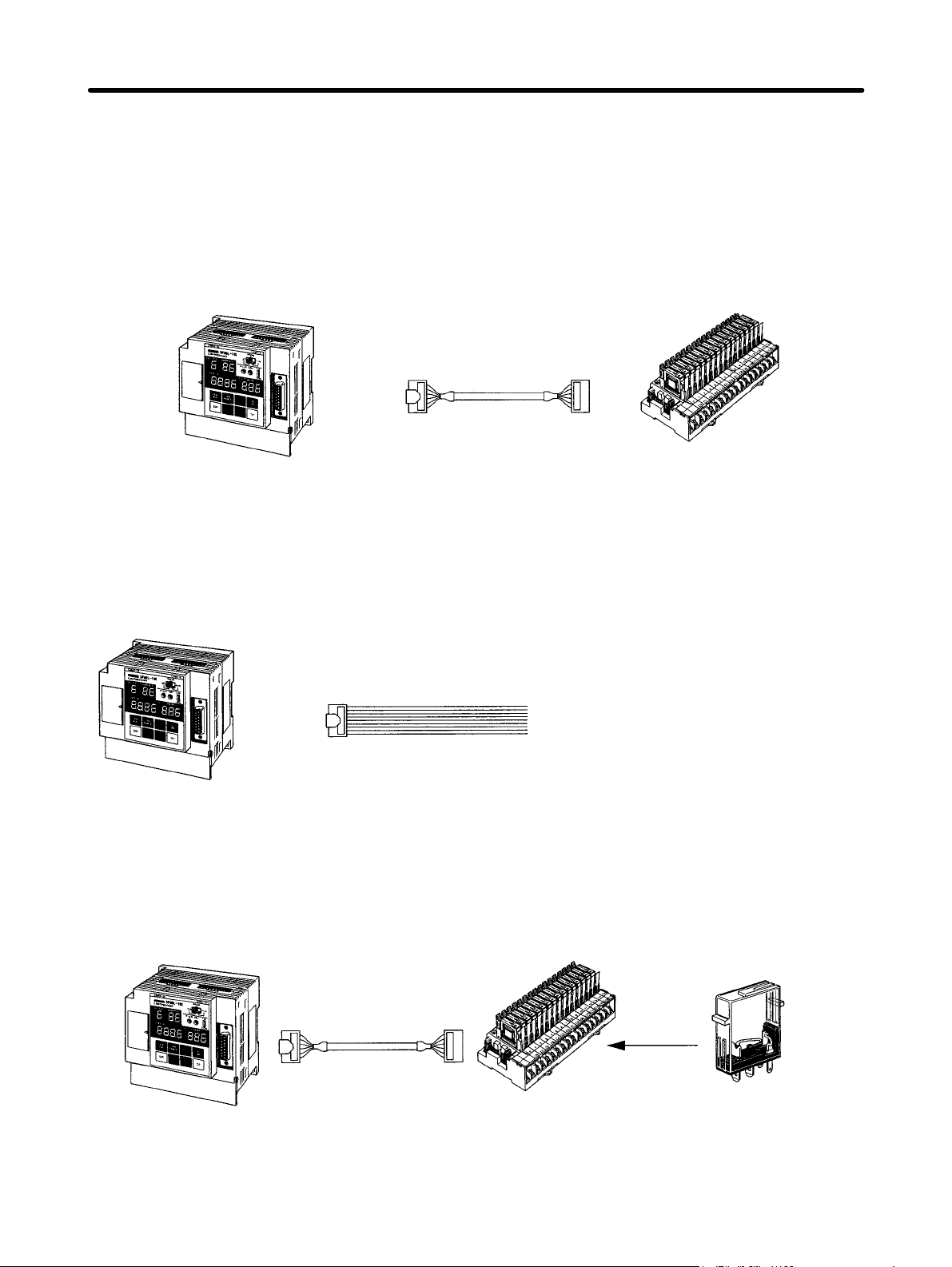
2-1-2 Selecting the Output Device
Select the device and connection method for ON/OFF outputs from the Cam Positioner. (Refer to 2-3
Wiring for information on connecting output devices.)
H For Relay Output
Use an I/O Block for relay output.
3F88L-160 or 3F88L-162
Cam Positioner
3F88L-CGjjjN
Cam Output Cable
G7TC-OC16
I/O Block
H For Transistor (Open Collector) Output
Use the outputs straight from the Cam Output Cable.
Open collector output
3F88L-160 or 3F88L-162
Cam Positioner
3F88L-CGjjjS
Cam Output Cable
H For Mostly Relay Output with Some Open Collector Output
Use an I/O Block and use an Output Short-circuit Module to give some open collector output.
3F88L-160 or 3F88L-162
Cam Positioner
2-4
3F88L-CGjjjN
Cam Output Cable
G7TC-OC16
I/O Block
Output
Short-circuit
Module
Page 31

Design Chapter 2
H To Display Present Angles and Other Data on a Display Unit
Connect a M7E or M7F Display Unit to the Cam Output Cable.
3F88L-160 or 3F88L-162
Cam Positioner
3F88L-CGjjjS
Cam Output Cable
M7E or M7F Display Unit
Note Parameters must be set to output present values. The present value output and cam output termi-
nals will be shared which means that some cam output signals can no longer be used.
2-5
Page 32

Design Chapter 2
2-2 Installation
2-2-1 External Dimensions
Note All units are in millimeters unless otherwise indicated.
H 3F88L-160 and 3F88L-162 Cam Positioners
w When the Resolver
Cable is connected
Two, 4.5 dia.
101±0.2
91± 0.2
2-6
Page 33

Design Chapter 2
Resolvers
3F88L-RS17 and 3F88L-RS17T
280.5 72 (81) (see note)
Four, 4.5 dia.
10–0.005/–0.017 dia.
40 dia.
50 0.3 dia.
35+0/–0.05 dia.
XM3A-1521 (OMRON) or the equivalent
15-pin D-sub Plug
Approx. 3 m
8.6 dia.
XM3D-1521 (OMRON) or the equivalent
15-pin D-sub Socket
Note The dimensions in parentheses are for the 3F88L-RS17T Resolver.
3F88L-RS15
16.5±0.5
3
9
5.5
6–0.004/–0.016 dia.
72
2.5
44 max.
8.6 dia.
43 dia.
33.32+0/–0.05
39 dia.
Hirose RM15WTP-10S-(8)
Connector
Hirose RM15WTR-10P
Connector
2-7
Page 34

Design Chapter 2
D 3F88L-RS15W
16
max.
16.5±0.5
6–0.004/–0.016 dia.
350 max.
43 dia.
33.32+0/–0.05
39 dia.
2-2-2 Installation Environment
Take precautions with the installation environment to improve the reliability and to fully
utilize the functions of the Cam Positioner system.
H Do not install the Unit in the following locations.
• Locations subject to direct sunlight.
• Locations subject to ambient temperatures or relative humidities outside the following ranges.
Ambient temperature: 0° to 55°C (Cam Positioner Unit) and –10° to 80°C (Resolver)
Ambient humidity: 10 to 90 % (with no condensation).
• Locations subject to condensation as the result of severe changes in temperature.
• Locations subject to corrosive or flammable gases.
• Locations subject to dust (especially iron dust) or salts.
• Locations subject to exposure to water, oil, or chemicals.
• Locations subject to shock or vibration.
H Take appropriate and sufficient countermeasures when installing the
Unit in the following locations.
• Locations subject to static electricity or other forms of noise.
• Locations subject to strong electromagnetic fields and magnetic fields.
• Locations subject to possible exposure to radioactivity.
• Locations close to power supplies.
2-8
Page 35

Design Chapter 2
H Conformance to EC Directives
The 3F88L-160/162 Cam Positioner complies with EC Directives. To ensure that the system in which
the 3F88L-160/162 is installed complies with EC Directives, the following precautions must be observed.
• The 3F88L-160/162 is defined as an in-panel device according to the Low-voltage Directive. The
3F88L-160/162 must, therefore, be installed within a control panel.
• Reinforced insulation or double insulation must be used for the DC power supplies used as I/O power
supplies.
• The 3F88L-160/162 conforms to the Common Emission Standard (EN50081-2) in relation to EMI.
However, the radiated emission (10-m regulations) may vary depending on the configuration of the
control panel, connected devices, wiring, and other conditions. The customer must, therefore, confirm
that devices and the overall machine conform to EC Directives.
2-2-3 Mounting the Resolver
Use the Resolver Coupling to connect the Resolver to the machinery. This Coupling protects the Resolver from vibrations and shocks from the machinery.
H Mounting Method
D 3F88L-RS17/17T (Flange-mounted)
w Recommended
mounting holes
Four, M4-screws
+0.025
35
dia.
/
+0.009
50 ± 0.3 dia.
w Mounting example
Four, M4
screws
50 dia.
3-mm sheet min.
2-9
Page 36

Design Chapter 2
D 3F88L-RS15/15W (Servo-mounted)
w Recommended
w Mounting example
mounting hole
Three, M4 screws
(Evenly spaced around
circumference)
33.332
dia.
52 dia.
+0.025
/
+0.009
52 dia.
67 dia.
3-mm sheet min.
w Mounting hook (Resolver attachment)
4.4 dia.
H Connecting with the Coupling
As a rule, the Resolver Coupling should be used when connecting the Resolver to the machinery. The
Coupling will break near the center if 1.7 to 2 times the rated tightening torque is applied and, therefore,
protects the Resolver from excessive torque.
Keep the axle center displacement and bend angle of the Coupling within the specifications when
mounting.
D Coupling Specifications
3F88L-
Cou-
plings
RL10 RS17/RS17J 10 22 26.2 19 3.6 7.1 12 10°
RL6 RS15/RS15W 6 15 22 16.4 2.8 5.5 11 10°
3F88L-
Resolvers
D dia. E dia. L P A B C
Dimensions (mm)
Max.
bend
angle
θ1 (see
note 2)
max.
max.
Axle cen-
note 3)
1.0 mm
max.
1.2 mm
max.
Note 1. The Coupling is made from 25% Duracon glass fiber.
Hexagonal set screw
D dia.
E dia.
ter dis-
place-
ment
t1 (see
Rated tightening
torque
+20°C +80°C Size Tighten-
2.94
N S m
0.98
N S m
1.76
N S m
0.58
N S m
Screw sets
ing
torque
M4 × 6 0.44
N S m
M3 × 4 0.24
N S m
2-10
Page 37

Design Chapter 2
Note 2. Maximum bend angle
Θ1
Note 3. Axle center displacement
t1
D Precautions when Connecting with the Coupling
Take the following precautions when connecting the Resolver to the machinery via the Coupling.
• Make sure the axle center does not protrude into the area marked C in the diagram. If the axle center is
protruding when the Resolver rotates, the Coupling will no longer function and the machinery may be
damaged.
• If the bend angle or displacement of the axle center is large, the life of the Coupling will be shortened
and the accuracy of the Resolver rotation angle will be adversely affected.
Resolver axle centerMechanical axle center
H Connecting without the Coupling
Give sufficient consideration to the load that will be applied to the Resolver axle if it is connected to the
machinery without the Coupling. Make sure the applied load will be below the rated load.
D Rated Resolver Axle Load
Model 3F88L-RS17 3F88L-RS17T 3F88L-RS15 3F88L-RS15W
Rated axle load Thrust load: 196 N max.
Radial load: 196 N max.
Thrust load (load
parallel to the axle)
Thrust load: 98 N max.
Radial load: 98 N max.
Radial load (load
perpendicular to
the axle)
2-11
Page 38

Design Chapter 2
D Connection Examples
Using a Timing Belt
A pulley is attached directly onto the Resolver axle and connected to a rotating machinery by a timing
belt.
In this case, the load on the axle is the tension on the timing belt and the weight of the pulley.
Timing belt
Resolver
Using Gears
Pitch errors, total alignment errors, and other gear errors apply a repeated load in the radial direction.
Gear
Resolver
Using Chains
A sprocket can be attached directly to the Resolver axle and the axle then connected to a rotating
machinery with a chain.
The weight of both the sprocket and the chain will be a load on the axle. Rattles in the sprocket and chain
will become shock loads applied to the axle when machine movement stops and starts.
Chain
2-12
Resolver
Page 39

Design Chapter 2
2-3 Wiring
2-3-1 System Connection Diagram
G7TC-OC16 I/O Block SYSMAC CS1 or other
3F88L-CGjjjN
Cam Output Cable
Programmable Controller
3F88L-CGjjjS
Cam Output Cable
Cam Output Connector
Display Units
M7E
M7F
3F88L-CGjjjS
Cam Output Cable
3F88L-160/162
Cam Positioner
Resolver Connection Cables
3F88L-CRjjjC
Resolver Extension Cable
3F88L-RS17/-RS17T Resolver 3F88L-RS15 Resolver 3F88L-RS15W Resolver
3F88L-CRjjjNA
Resolver Cable
3F88L-CRjjjSA
Resolver Cable
2-13
Page 40

Design Chapter 2
2-3-2 Standard Wiring Method
The number of man hours required for wiring will be reduced and the reliability of the Unit
will be improved if OMRON Cables are used.
Give sufficient consideration to noise countermeasures when wiring
H Using Connection Cables
Use the following Cables to connect the Unit to peripheral devices. Always use OMRON Cables when
connecting the Resolver, in particular, to ensure reliability of the Unit.
Peripheral device
Cable name Model Remarks
to be connected
Resolver Resolver Cable
I/O Block Cam Output Cable
PC or similar device
Cam Output Cable
3F88L-CRjjjC
3F88L-CRjjjNA
3F88L-CRjjjSA
3F88L-CGjjjN
3F88L-CGjjjS
Extension Cable for 3F88L-RS17/-RS17T
Cable for 3F88L-RS15
Cable for 3F88L-RS15W
Connectors at both ends.
Connector on one end.
(for cam output)
Display Unit Cam Output Cable
3F88L-CGjjjS
Connector on one end.
Note The jjj in the cable model numbers indicates the length of the cable. Refer to 7-4 Standard
Models for details.
H Wiring for Improved Noise Resistance
The noise resistance of the system can be improved by the wiring method. The following points must be
given attention when wiring.
D Connection Method
Control panel
AC power
supply
Power
device
2-14
Surge
absorber
Insulation
transformer
Noise filter
Control
power
supply
Ground board
Control
device
Cam
Positioner
Ground to 100 Ω or less.
Resolver
If metal ducted
2
2.0 mm
ground min.
Page 41

Design Chapter 2
• Use a ground board as shown in the diagram and ground (FG) each Unit to one point on the ground
board.
• Do not bundle the ground together with the power supply, motor drive, or Resolver signal wires or run
the ground through the same duct as these wires.
• If using metal conduit or running wires through metal duct, ground the metal to one point.
Note To make the 3F88L-160/162 Cam Positioner conform to EC Directives, be sure to install the Unit
within a control panel.
D External Wiring
• Use a different cable for the Cam Positioner I/O and the control wire. Do not run these wires through
the same cable.
• It is recommended that the Cam Positioner cables and other control and power cables are wired as
shown below.
• Parallel cable racks must be a minimum of 300 mm apart.
• If multiple terminals are to be housed in one duct, shield the terminals with a grounded conductive
plate.
Low-current
cable
1
2
Control cable
3
Power cable
4
Conductive
plate (steel)
300 mm min.
300 mm min.
1. Resolver cable
2. Cam Positioner input cable
3. Cam Positioner power supply cable
General control cable
4. Power cable
Ground to 100 Ω or less
Conductive
plate (steel)
12 3 4
Ground to 100 Ω or less
200 mm min.
Note The 3F88L-160/162 conforms to the Common Emission Standard (EN50081-2) in relation to
EMI. However, the radiated emission (10-m regulations) may vary depending on the configuration of the control panel, connected devices, wiring, and other conditions. The customer must,
therefore, confirm that devices and the overall machine conform to EC Directives.
H Points to Consider when Wiring to Peripheral Devices
• Install a surge absorber and noise filter on the AC power supply input wiring.
• Pay attention to the following points when using relays, electromagnetic valves, and other noise-gen-
erating devices.
S Separate noise-generating devices, parts and the wiring as much as possible.
S Use a separate power supply system.
2-15
Page 42

Design Chapter 2
S Use a separate grounding system.
S Attach a surge absorber or diode to the device or parts generating the noise, as shown in the fol-
lowing diagram.
AC relays or AC valves DC relays
AC
power
supply
~
Surge absorber
DC
power
supply
Note Select withstand pressure and current suitable for the load.
2-3-3 Terminal Block Wiring
Use crimp terminals and firmly tighten to the appropriate torque.
H Terminal Block Layout
Power supply input
Function
Earth
Protect
Earth
Control input
Diode
Control output
H Power Supply Input Wiring
D Wiring Method
Func-
Protect
tion
Earth
Earth
100 to 240 V AC
50/60 Hz
2-16
~
Ground to 100 Ω
or less
Terminal screw size: M3.5
Tightening torque: 0.8 N S m
Page 43

input terminal
Positioner. Provide a 100 to 240 V AC
Design Chapter 2
D Terminal Functions
Terminal name Symbol Function Recommended
connection wire
diameter
Main circuit power supply
input terminal
Function earth terminal This is the primary ground terminal
Protect earth terminal This is the frame ground terminal. 2.0 mm
AC1/L
AC2/N
Inputs the AC power supply for the Cam
Positioner. Provide a 100 to 240 V AC
50/60 Hz power supply. (Rated power
supply voltage 85 to 264 V AC)
connected for the power supply.
1.25 mm
2.0 mm
Note 1. Use M3.5 round crimp terminals for AC 1/L and AC 2/N terminals.
Note 2. Use M3.5 round or forked crimp terminals for function earth and protect earth terminals.
w Round crimp terminal w Forked crimp terminal
2
2
2
7 mm max.
7 mm max.
Note If the power supply voltage of the Cam Positioner slowly increases or decreases at less than 85%
of the rated voltage (i.e., less than 85 V), operation may stop intermittently. If this affects the operation of equipment, provide protective circuits that interrupt output enough to cause the voltage
to increase to more than 85% of the rated value.
H Control Input Wiring
D Wiring Method
24 V DC
Terminal screw size: M3
Tightening torque: 0.5 N S m
2-17
Page 44

p
pp y
Design Chapter 2
D Terminal Functions
Terminal
name
Control I/O
power
supply
Operation
start input
Bank
switching
input
Symbol Function Recommended
connection
wire diameter
24 V
The control I/O power supply terminal is used for the power
1.25 mm
2
supply for control I/O.
0 V
Provide a 24-V DC power supply. (Rated power supply voltage
20.4 to 26.4 V DC)
START Cam output will start if the START signal is shorted with 0V. 0.5 mm
BANK1 The BANK signals are used to select the execution bank for the
0.5 mm
2
2
Cam Positioner.
The BANK signals turn ON when shorted with 0V.
BANK2
Bank No. 1 2 3 4 5 6 7 8
BANK1 OFF ON OFF ON OFF ON OFF ON
BANK3
BANK2 OFF OFF ON ON OFF OFF ON ON
BANK3 OFF OFF OFF OFF ON ON ON ON
Origin shift
input
TRIG
Origin shift is performed when this signal is shorted with 0V.
Note 1. The TRIG signal is disabled when the Resolver rotates at
0.5 mm
2
4 r/min or greater.
Note 2. The TRIG signal is enabled when it is ON for 10 ms or
more.
Inside
Origin shift execution
Reset input RESET If this signal is shorted with 0V, a hardware reset will be
New origin value
Y
0.5 mm
2
performed and the Unit will return to the state it was in upon
power ON. Regardless of output-hold settings, all outputs will be
turned OFF. Also, the origin value for the origin shift will be lost.
Note 1. Use M3.5 round or forked crimp terminals for functional ground and protective ground termi-
nals.
w Round crimp terminal w Forked crimp terminal
6.2 mm
max.
6.2 mm
max.
Note 2. Reinforced insulation or double insulation must be used for the DC power supplies used as
I/O power supplies in order to comply EC Directives.
2-18
Page 45

Design Chapter 2
D Control Input Specifications
Item Specification
Rated input voltage 24 V DC –15%/10%
Input impedance 4.7 kΩ
Input current 4.7 mA TYP. (for 24 V DC input)
ON voltage 17 V min. between 24-V terminal and control input terminals.
OFF voltage 5 V max. between 24-V terminal and control input terminals.
ON/OFF response time 1.0 ms
Internal circuit
START
BANK1 to 3
TRIG
RESET
H Control Output Wiring
4.7 kΩ
D Wiring Method
LL
Terminal screw size: M3
MSDET
L
COM
/0 V
24 V DC
for load
Tightening torque: 0.5 N S m
D Terminal Functions
Terminal name Symbol Function Recommended
connection wire
Control output common
terminal
RUN output RUN The RUN terminal indicates the operation
Resolver movement
detection output
Error output ERROR The ERROR terminal turns OFF when an
COM/0 V The COM/0 V terminal is the common
terminal for control output.
It is connected to the 0V terminal on the
control I/O output power supply.
status of the Unit.
It turns ON when cam output is enabled.
MSDET
The M⋅DET terminal turns ON when the
Resolver is rotating at 4 r/min or faster.
error is generated.
0.5 mm
0.5 mm
0.5 mm
0.5 mm
diameter
2
2
2
2
2-19
Page 46

Design Chapter 2
Note 1. Use M3.5 round or forked crimp terminals for functional ground and protective ground termi-
nals.
w Round crimp terminal w Forked crimp terminal
6.2 mm
max.
6.2 mm
max.
Note 2. Reinforced insulation or double insulation must be used for the DC power supplies used as
I/O power supplies in order to comply EC Directives.
Note 3. The control I/O power supply must be turned ON to operate the control output circuit.
D Control Output Specifications
Item Specification
Maximum switching capacity 24 V DC –15%/10%, 0.3 A/point
Leakage current 0.1 mA max.
Residual voltage 1.5 V max.
ON response time 0.5 ms max.
OFF response time 1.0 ms max.
Internal circuit
RUN
M-DET
ERROR
2-20
Page 47

Design Chapter 2
2-3-4 Resolver Wiring
Use OMRON Resolver Cables which are designed to reduce noise.
Resolver Cables transfer signals that require a high degree of accuracy. Separate the
Resolver Cables from other cables as much as possible to prevent the accuracy being
affected by induction noise resulting from low signal voltage.
S Separate Resolver Cables as much as possible from control and drive wiring inside
the control panel.
S For external wiring, house the cables in a low-current duct and shield with grounded
conduction plates.
The Cam Positioner and Resolver can be separated by a maximum distance of 100 m.
H Resolver Wiring Method
3 m plug-in cable
3F88L-160/162 Cam Positioner 3F88L-RS17/-RS17T Resolver
3F88L-160/162 Cam Positioner 3F88L-RS15 Resolver
3F88L-160/162 Cam Positioner 3F88L-RS15W Resolver
3F88L-CRjjjC Extension Cable
Connector type
3F88L-CRjjjNA Cable
35-cm Separate wire
plug-in cable
3F88L-CRjjjSA Cable
2-21
Page 48

Design Chapter 2
D Resolver Cable Models
Resolver Extension Cables (for 3F88L-RS17/-RS17T)
2 m 3F88L-CR002C
5 m 3F88L-CR005C
10 m 3F88L-CR010C
20 m 3F88L-CR020C
50 m 3F88L-CR050C
Note 1. A maximum of two extension cables can be joined together.
Note 2. Refer to 6-2 Resolver Specifications for information on cable wire colors and pin positions.
Resolver Cables (for 3F88L-RS15)
3 m 3F88L-CR003NA
5 m 3F88L-CR005NA
10 m 3F88L-CR010NA
15 m 3F88L-CR015NA
20 m 3F88L-CR020NA
Resolver Cables (for 3F88L-RS15W)
3 m 3F88L-CR003SA
5 m 3F88L-CR005SA
10 m 3F88L-CR010SA
2-3-5 Cam Output Wiring
Cam output is an open-collector output. The wiring connectors are located on top of the
Cam Positioner Unit and the wiring is easily performed if Cam Output Cables are used.
H Cam Output Wiring Method
Use the 3F88L-CGjjjS Cam Output Cable for direct connection to PCs or Relays and the
3F88L-CGjjjN Cam Output Cable for direct connection to an I/O Block.
Note Cam output is also used for connection to Display Units. Refer to 2-3-6 Connecting a Display Unit
for details.
Cam Output Connectors
CAM17 to 32
CAM1 to 16
G7TC-OC16
I/O Block
3F88L-CGjjjN
Cam Output Cable
3F88L-160/162
Cam Positioner
2-22
PC or Relay
3F88L-CGjjjS
Cam Output Cable
Page 49

Design Chapter 2
Note The 3F88L-160 16-output Cam Positioner does not have cam output connector terminal numbers
CAM17 to CAM32.
D Cam Output Cable Models
Cam Output Cables for Connection to I/O Blocks
0.5 m 3F88L-CG0R5N
1 m 3F88L-CG001N
Cam Output Cables for Connection to Other Devices
1 m 3F88L-CG001S
3 m 3F88L-CG003S
H Cam Outputs for I/O Blocks
3F88L-160/162
Cam Positioner
G7TC-OC16 I/O Block
3F88LCGjjjN
––
++
+
–
2-23
Page 50

Design Chapter 2
H Cam Output Cable Connection Pin Positions and 3F88L-CGjjjS
Cam Output Cable Colors
Pin Layout
Positioner
Pin No. Signal name Cable color Pin No. Signal name Cable color
A1 NC Brown B1 NC Brown
A2 COM/0V Red B2 COM/0V Red
A3 CAM16 (CAM32) Orange B3 CAM8 (CAM24) Orange
A4 CAM15 (CAM31) Yellow B4 CAM7 (CAM23) Yellow
A5 CAM14 (CAM30) Green B5 CAM6 (CAM22) Green
A6 CAM13 (CAM29) Blue B6 CAM5 (CAM21) Blue
A7 CAM12 (CAM28) Purple B7 CAM4 (CAM20) Purple
A8 CAM11 (CAM27) Gray B8 CAM3 (CAM19) Gray
A9 CAM10 (CAM26) White B9 CAM2 (CAM18) White
A10 CAM9 (CAM25) Black B10 CAM1 (CAM17) Black
ExternalCam
Cam output
COM/0V
Note 1. Pin numbers have been given for convenience. The pin “A1”, indicated by the Y mark on the
protruding side, should be used as the starting pin number.
Note 2. The signal names in parentheses in the table will be applicable if the Cam Connector Cable is
connected to the connectors for cam outputs 17 to 32 (CAM17 to CAM32). These connectors
are not available on the 3F88L-160 16-point Cam Positioner.
Note 3. The maximum switching capacity for cam outputs is 26.4 V DC, 300 mA. However, keep this
at no more than 1.6 A per connector.
Note 4. The COM/0V connector is common to both A2 and B2 pins.
Note 5. If the present value output function is used, some cam outputs cannot be used.
Note 6. Reinforced insulation or double insulation must be used for the DC power supplies used as
I/O power supplies in order to comply EC Directives.
2-24
Page 51

Design Chapter 2
H Cam Output Specifications
Item Specifications
Maximum switching capacity 24 V DC –15%/10%, 0.3 A/point, 1.6 A/connector
Leakage current 0.1 mA max.
Residual voltage 1.5 V max.
ON response time 0.05 ms max.
Off response time 0.07 ms max.
Internal circuit
CAM1 to 32
2-3-6 Connecting a Display Unit
If the Cam Positioner is connected to a Display Unit, the present angle and Resolver
speed can be displayed.
The Display Unit is connected to the cam output connectors on the Unit via Cam Output
Cables.
Note 1. The speed display can have an error margin or 5 r/min max.
Note 2. Parameters must be set to display present values such as the present angle
and Resolver speed. The present value output and cam output share terminals. Some cam output signals can no longer be used, therefore, when present values are being output.
H Connecting a M7E Display Unit
Use a 3F88L-CGjjjS Cam Output Cable to connect the M7E Display Unit.
3F88L-160/162 Cam Positioner
3F88L-CGjjjS Cam Output Cable
M7E Display Unit
D Functions
The present angle (in degrees) or the Resolver speed (r/min) can be displayed on a 3- or 4-digit Display
Unit. The display data is set using the present value display function parameters.
2-25
Page 52

py
ypy
py ( )
ygpy
(
a degrees Unit
q
p
pq
tti
for
t
/
py
Design Chapter 2
If set to an automatically switching display, the present angle will be displayed when the Resolver speed
is less than 4 r/min and the Resolver speed will be displayed when it is greater than 4 r/min.
D Unit Models Used
Name Model Remarks
Display Unit
(Numerals)
Display Unit (Units)
End Plate
Display Unit
Connector
Cam Output
Cable
1 m 3F88L-CG001S
3 m 3F88L-CG003S
M7E-01DRD2 (red, decimal, one digit)
M7E-01DGD2 (green, decimal, one
digit)
M7E-01UR2-V (red, rpm)
M7E-01UG2-V (green, rpm)
M7E-01UR2-A (red, no display)
M7E-01UG2-A (green, no display)
M7E-2M (light-blue case)
M7E-2M-1 (black case)
NRT-C (soldered-terminal type) Enough connectors for the number of
Combine as many Display Units
(Numerals) as required to achieve the
required number of display digits.
If the automatically switching display
function is to be used, two Display Units
“
Units) are required – an “r/min” Unit and
“
One set is required.
Display Units is required.
One Cam Output Cable is required.
”
.
”
D Display Contents and Required Number of Units
Display Resolution
se
ng
Present
angle
r/min 360 2
Switching
present
angle/r/min
display
360 1 0 to 359 3 --- 3
720 1 0 to 719 3 --- 3
720 2 0 to 800 3 --- 3
360
720 3 0 to 719
Parameter
presen
value output
function
3 0 to 359
4 0 to 359
Display
range
0 to 999 3 --- 3
0 to 1,600 4 --- 4
(degrees)/
4 to 999
(r/min)
(degrees)/
4 to 1,600
(r/min)
(degrees)/
4 to 800
(r/min)
Required number of Units
Numeric
Display Unit
3 1 no display
4 1 no display
3 1 no display
Units
Display Unit
Unit and 1
“rpm” Unit
Unit and 1
“rpm” Unit
Unit and 1
“rpm” Unit
Display Unit
Connectors
5
6
5
Note 1. Refer to 3-5-2 Initial Settings for information on setting the display resolution.
Note 2. Refer to 3-6-10 Present Value Output Function for information on parameters for this function.
Note 3. One 3F88L-CGjjjS Cam Output Cable and one End Plate set are required when connect-
Note 4. When the resolution is set at 720, the present angle display will read “1” for every 0.5°.
2-26
ing Units other than those listed in the above table.
Page 53

Design Chapter 2
D Wiring Example
The following wiring example is for automatically switching the 4-digit display between the present
angle and the Resolver speed (with units also displayed).
Cam Output Connectors
Signal name Pin No.
CAM13 (CAM29)
Display data
1-digit LE signal
2-digit LE signal
3-digit LE signal
4-digit LE signal
“Degrees”
“r/min”
Common cam
output terminal
CAM14 (CAM30)
CAM15 (CAM31)
CAM16 (CAM32)
CAM12 (CAM28)
CAM11 (CAM27)
CAM10 (CAM26)
CAM9 (CAM25)
CAM8 (CAM24)
CAM7 (CAM23)
COM/0V
Blue
Green
Yellow
Orange
Purple
Gray
White
Black
Orange
Yellow
Red
12 to 24 V DC
(see
note 1)
M7E Display Unit
4th digit
(1,000’s
digit)
M7E01jjj2
3rd digit
(100’s
digit)
M7E01jjj2
2nd digit
(10’s digit)
M7E01jjj2
1st digit
(1’s digit)
M7E01jjj2
No display
M7E01Uj2-A
r/min
M7E01Uj2-V
Note 1. If pin 9 (4th digit) is left open, a zero (0) will appear as “0.” In the above wiring example, an
output of 0 would appear as “0000.”
Note 2. The cam output signal names not in parentheses will be displayed for 3F88L-160 Cam Posi-
tioners and the names in parentheses will be displayed for 3F88L-162 Cam Positioners.
Note 3. The circled numbers in the diagram are the terminal numbers for the NRT connectors.
Note 4. Reinforced insulation or double insulation must be used for the DC power supply used as an
I/O power supply in order to comply to EC Directives.
2-27
Page 54

gpy, g
pp p
gpy(),
display, and color of displayed
characters.
p, g
When using a Unit with units
py p
gpy, g
displ
Th
it
Nameplate for degrees. Select
gpy(),
py p
p, g
py
p
q
Design Chapter 2
Note 5. Some display examples are given below.
w Present angle display w Resolver speed display
(see
(blank)
note)
Note Write “deg” in the space when using a no display Unit.
H Connecting a M7F Display Unit
Use a 3F88L-CGjjjS Cam Output Cable to connect the M7F Display Unit.
(blank)
rpm
3F88L-160/162
Cam Positioner
3F88L-CGjjjS
Cam Output Cable
M7F Display Unit
D Functions
The present angle (in degrees) or the Resolver speed (r/min) can be displayed on a 4-digit numeric
Display Unit. The display data is set using the present value display function parameters.
Note The M7F Display Unit does not have a function to change the unit of display. Do not use this Unit in
automatically switching display mode.
D Unit Models Used
Name Model Remarks
4-digit Display Unit, character height
14 mm
4 digits + Display Unit (Units),
character height 14 mm
Units Nameplate, character height
14 mm
4-digit Display Unit, character height
25 mm
4 digits + Display Unit (Units),
character height 25 mm
Unit nameplate, character height
25 mm
Display Unit Connector XG5M-2035-N (separately wired
Display Unit Connector Cover
Cam Output Cable
1 m 3F88L-CG001S
3 m 3F88L-CG003S
M7F-4D1R (red)
M7F-4D1G (green)
M7F-4D1RT (red)
M7F-4D1GT (green)
M7F-1 (no display)
M7F-RPM-1 (r/min)
M7F-4D2R (red)
M7F-4D2G (green)
M7F-4D2RT (red)
M7F-4D2GT (green)
M7F-2 (no display)
M7F-RPM-2 (r/min)
pressure-welded type)
XG5S-1001
XG5S-2012
Select the appropriate Unit
based on the display character
height, requirements for units
characters.
When using a Unit with units
display, select a Unit Nameplate
with the same height character
ay.
ere is no Un
Nameplate for “degrees.” Select
the “no display” Unit Nameplate
instead.
One Display Unit Connector is
required.
Two XG5S-1001 Covers or one
XG5S-2012 Cover is required.
One Cable is required.
2-28
Page 55

Design Chapter 2
D Wiring Example
The following wiring example is for four-digit display of the Resolver speed.
Cam Output Connectors
Signal name Pin No.
Display data
Common cam
output terminal
1-digit LE signal
2-digit LE signal
3-digit LE signal
4-digit LE signal
CAM13 (CAM29)
CAM14 (CAM30)
CAM15 (CAM31)
CAM16 (CAM32)
COM/0V A2
CAM12 (CAM28) A7
CAM16 (CAM32) A8
CAM16 (CAM32) A9
CAM16 (CAM32) A10
A8
A5
A4
A3
12 to 24 V DC
Blue
Green
Yellow
Orange
Red
Purple
Gray
White
Black
ę
Ĝ
V
Power
supply
input
Power
supply
output
M7F Display Unit
Case mark
Note 1. The cam output signal names not in parentheses will be displayed for 3F88L-160 Cam Posi-
tioners and the names in parentheses will be displayed for 3F88L-162 Cam Positioners.
Note 2. The circled terminal numbers have been provided for convenience. When assembling the
socket, pay attention to the direction of the polarity guide and connect the wires as shown in
the above terminal layout.
Note 3. The case mark (Y) indicates the first digit of the M7F terminal number and is different from the
connector Y mark described previously.
Note 4. A display example is shown below.
w Resolver speed display
rpm
Unit Nameplate
2-29
Page 56

Page 57

3
Chapter 3
Operation
3-1 Nomenclature of Display and Operation
Sections
3-2 Modes, Functions, and Display
3-3 Operation Procedure
3-4 Selecting Function Levels
3-5 Basic Operation
3-6 Applied Functions
Page 58

Operation Chapter 3
3-1 Nomenclature of Display and Operation Sections
Bank/Function display
Cam/Parameter No. display
Mode selection switch
P⋅CLR switch
ADJ switch
CW/CCW setting switch
H Operation Keys
BANK/
FUN
CAM/
PRMTR
ON/
OFF
Bank/Function Key Down Key
Cam/Parameter Key Forward Key
ON/OFF Switching Key
CLR
Operation keys
Present angle/OFF angle
display
No. of revolutions/ON angle
display
Clear Key
3-2
Up Key
SET
Set Key
Page 59

Operation Chapter 3
H Display Patterns for Seven-segment Display
Marks underneath a character display indicate that the character is flashing.
3-3
Page 60

ca o
e ce sec
Operation Chapter 3
3-2 Modes, Functions, and Display
H Modes
The 3F88L-160/162 Cam Positioner has three modes: SET, PRGM, and RUN.
Set Mode (SET)
S Unit parameter settings
S Various compensation
value settings
S Teaching
S Communications settings
S Origin compensation
Mode
change
Program Mode (PRGM) Operation Mode (RUN)
S Creation, editing, and
deletion of cam programs.
S Trial operation
H Changing Modes
The mode selection switch is used to change modes.
Mode
change
Mode selection switch
S Normal operation
S Adjustment operation
S Cam output and control
I/O monitoring
S Origin shift
H Functions by Mode
Classifi-
cation
Function
selection
Initial
settings
3-4
Function name Applicable modes Conditions
Function level selection SET --- U 1 3-5-1
Resolution selection SET --- A 1 3-5-2
Rotation direction
selection
SET, PRGM, RUN
Note The CW/
CCW setting
switch is
used.
Front panel
displays
Function
No.
--- --- --- 3-5-2
Parame-
ter No.
Refer-
ence sec-
tion
Page 61

Operation Chapter 3
Classifi-
cation
cation
Basic
functions
ConditionsApplicable modesFunction nameClassifi-
ConditionsApplicable modesFunction name
Function
No.
Cam program writing PRGM --- 1 to 8
Program number
checking
Origin compensation Press the ADJ switch
Cam output (from cam
output connector)
Con -
Input
signals
Output
signals
START
(Start
operation)
BANK1 to
3 (Change
banks)
TRIG
(Origin
shift)
RESET
(Reset)
RUN (Cam
output
enabled)
M-DET
(Resolver
rotation
detection)
ERROR
(Error)
trol
I/O
I/O monitor RUN (Possible when
SET --- 0 to 8
in SET mode.
RUN (only when
START signal is ON)
PRGM (Only during
trial operation)
RUN
Note This signal is
disabled and
cam output is
executed
when in
PRGM mode
and a trial operation.
RUN --- --- ---
RUN --- --- ---
SET, PRGM, RUN --- --- ---
RUN (Only when
START signal is ON)
PRGM (Only during
trial operation)
RUN
PRGM (Only during
trial operation)
SET, PRGM, RUN OFF when an error
START signal is ON
or OFF.)
The Resolver speed
must be less than 4
r/min.
Output during normal
operation
(Depending on the
output holding
function when error
is generated and the
type of error, cam
outputs may be held
or turned OFF.)
--- --- ---
ON during normal
operation (cam
output enabled).
ON when Resolver
speed is 4 r/min or
greater.
has been generated.
--- o 1, 2 3-5-7
(1 to 4)
(see note
2)
(0 to 4)
(see note
2)
--- --- 3-5-5
--- --- 3-5-6
--- ---
--- ---
--- ---
Front panel
displays
Parame-
ter No.
1 to 32
(1 to 16)
(see note
1)
--- 3-5-3
Refer-
Refer-
ence sec-
ence sec-
tion
tion
3-5-3
3-5-8
3-5
Page 62

Operation Chapter 3
Classifi-
cation
cation
Applied
functions
ConditionsApplicable modesFunction nameClassifi-
ConditionsApplicable modesFunction name
Origin compensation
value setting
Note Origin com-
pensation can
also be performed as a basic function at
function level 0
or 1
Origin shift (operation)
Note Used for both
origin compensation operation and
compensation
value.
Backlash compensation
value setting
Enable/disable
backlash compensation
setting
Backlash compensation RUN
Advance angle
compensation setting
Advance angle
compensation
enable/disable setting
Advance angle
compensation
Cam protect setting SET --- C ---
Cam protect function
(operation)
One-direction function
setting
One-direction function
(operation)
Output hold setting SET --- H 3 3-6-9
SET --- b 1
TRIG input in RUN
mode (possible when
START signal is ON
or OFF.)
SET --- b 2
SET --- H 1
PRGM (trial
operation only)
SET (only when
teaching)
SET --- b 3, 4, 5
SET --- H 2
RUN
PRGM (trial
operation only)
SET (only when
teaching)
PRGM The power must be
SET --- F ---
RUN (except during
compensation
operation)
Resolver speed must
be less than 4 r/min.
Only when backlash
compensation value
is enabled.
--- --- ---
reset to ON after
cam protect has
been set.
--- --- ---
Front panel
displays
Function
No.
--- ---
--- ---
--- ---
Parame-
ter No.
Refer-
Refer-
ence sec-
ence sec-
3-6-4
3-6-5
3-6-6
3-6-7
3-6-8
tion
tion
3-6
Page 63

g/
gg
Operation Chapter 3
Classifi-
cation
cation
Applied
functions
Output hold function
(operation)
Present value output
setting
Present value output
function (operation)
Cam program
creating/
changing
Cam outputs/cam
program
changing
Communications
Pulse
output
setting
Teaching SET Resolver speed must
Trial
operation
Adjustment
operation
CompoWay/F
communications
function
Copy SET --- t --- 3-6-13
Baud rate
setting
(shared
with CompoWay/F
and copy
operation.)
ConditionsApplicable modesFunction nameClassifi-
ConditionsApplicable modesFunction name
When switching from
RUN mode to PRGM
or SET mode (when
the START signal is
ON).
SET --- H 4
SET, PRGM, RUN The power must be
SET --- P --- 3-6-11
PRGM --- 1 to 8
RUN --- 1 to 8
SET, PRGM, RUN
(the content of the
communications will
differ for each mode.)
SET --- b 6 4-1
The power must be
reset to ON after
output hold has been
set.
The START signal
must be ON (cam
outputs will be OFF if
the START signal is
OFF).
The RESET signal
must be OFF (cam
outputs will be OFF if
the RESET signal is
ON).
reset to ON after
present value output
has been set.
Shared with a cam
output.
be less than 4 r/min.
--- --- --- Chapter 4
Front panel
displays
Function
No.
--- --- 3-6-9
--- ---
d --- 3-6-12
(1 to 4)
(see note
2)
(1 to 4)
(see note
2)
Parame-
ter No.
1 to 32
(1 to 16)
(see note
1)
1 to 32
(1 to 16)
(see note
1)
Refer-
Refer-
ence sec-
ence sec-
tion
tion
3-6-10
3-6-14
3-6-14
3-6-13
Note 1. The data for the 3F88L-160 (16-point model) Cam Positioner is shown in parentheses.
Note 2. The data for 720 resolution (divisions/revolution) is shown in parentheses.
3-7
Page 64

()
Operation Chapter 3
H Displays by Mode
D SET Mode
Bank/Func-
tion
1 to 8
(1 to 4)
(see note 2)
A (a) 1 Resolution
b (b)
Cam/Parame-
ter
0 Origin
1 to 32
(1 to 16)
(see note 1)
1 Origin
2 Backlash
3 Advance angle
4 Advance angle
5 Advance angle
6 Baud rate 1, 2 1: 9,600 bps (factory
Function Data range SPEED/ON POSITION/OFF
--- Displays the
compensation
absolute angle
Program
number
checking
selection
compensation
value
compensation
value
compensation
value 1
compensation
value 2
compensation
value 3
--- Displays the number
0, 1 0: 360 divisions/
0 to 359
(0 to 719)
(see note 2)
0 to 179
(0 to 359)
(see note 2)
0 to 1600
(0 to 800)
(see note 2)
0 to 359
(0 to 719)
(see note 2)
0 to 1600
(0 to 800)
(see note 2)
0 to 359
(0 to 719)
(see note 2)
0 to 359
(0 to 719)
(see note 2)
absolute angle for
origin compensation.
of steps for the
displayed bank or
cam number.
revolution (factory
setting)
1: 720 divisions/
revolution
Sets origin
compensation value
(angle data).
Factory setting “0.”
Sets backlash
compensation value
(angle data).
Factory setting “0.”
Sets speed data for
advance angle
compensation value
1.
Factory setting “0.”
--- Sets angle data for
Sets speed data for
advance angle
compensation value
2.
Factory setting “0.”
--- Sets angle data for
--- Sets angle data for
setting)
2: 19,200 bps
---
---
---
---
---
---
advance angle
compensation value
1.
Factory setting “0.”
---
advance angle value
2.
Factory setting “0.”
advance angle
compensation value
3 (advance angle
compensated
position).
Factory setting “0.”
---
3-8
Page 65

Operation Chapter 3
Bank/Func-
tion
c (c) --- Cam protect --- Protection can be set
d (d) --- Teaching --- Present Resolver
F (f) --- One-direction
H (h)
ter
or released for each
cam number or for
all cams in a bank
number.
(Factory setting:
“unprotected”)
angle can be input
as ON angle data.
0 to 2 --- 0: One-direction
function setting
1 Backlash
compensation
enable/disable
setting
2 Advance angle
compensation
enable/disable
setting
3 Output hold 0, 1 0: Output hold
0, 1 0: Backlash
compensation
disabled (factory
setting)
1: Backlash
compensation
enabled
0, 1 0: Advance angle
compensation
disabled (factory
setting)
1: Advance angle
compensation
enabled
disabled (factory
setting)
1: Output hold
enabled
POSITION/OFFSPEED/ONData rangeFunctionCam/Parame-
Protect can be set or
released for each
cam number or for
all cams in a bank
number (Factory
setting
“unprotected”)
Present Resolver
angle can be input
as OFF angle data.
function disabled
(factory setting)
1: Enabled in
forward direction
2: Enabled in
reverse direction
---
---
---
3-9
Page 66

Operation Chapter 3
Bank/Func-
tion
H (h) 4 Present value
P (p)
(see note 4)
t (t)
(see note 4)
U (u) 1 Function level
--- --- Error display --- E–** (error display) ---
ter
output setting
--- Pulse output
setting
0 Data transfer
(Slave setting)
1 Data transfer
(Master setting)
selection
0 to 4 0: No present value
output function
(factory setting)
1: 4-digit present
angle (no units)
2: 4-digit number of
rotations (no
units)
3: Automatic
switching of 3-digit
present angle and
number of
rotations (with
units)
4: Automatic
switching of 4-digit
present angle and
number of
rotations (with
units)
--- Writes pulse output
program to any bank
or cam number (sets
pulse number).
--- (Operates on a
command issued
from Master Unit.)
0 to 3 0: Disabled (factory
setting)
1: Read data
2: Write data
3: Verify data
0 to 2 0: Function level 0
(monitor only)
1: Function level 1
(basic
operation/monitor
only) (factory
setting)
2: Function level 2
(all functions)
---
(Sets pulse start
position.)
---
---
---
POSITION/OFFSPEED/ONData rangeFunctionCam/Parame-
Note 1. The data for the 3F88L-160 (16-point model) Cam Positioner is shown in parentheses.
Note 2. The data for 720 resolution (divisions/revolution) is shown in parentheses. The angles will be
set and displayed as “1” for 0.5°.
Note 3. Functions A, b, C, F, H, and U will be enabled after the power has been turned OFF and then
ON again.
Note 4. Functions P and t are special operations that are not stored as parameters.
3-10
Page 67

g
( )
Operation Chapter 3
D RUN Mode
Bank/Function Cam/Parameter Start input SPEED/ON POSITION/OFF
1 to 8
(1 to 4) (see note 2)
1 to 8
(1 to 4) (see note 2)
o (o)
--- --- --- E–** (error display) ---
--- OFF
ru (rU) ON
1 to 32
(1 to 16) (see note 1)
1 --- Cam output monitor
2 --- Control I/O monitor
ON Compensation op-
Note 1. The data for the 3F88L-160 (16-point model) Cam Positioner is shown in parentheses.
Note 2. The data for 720 resolution (divisions/revolution) is shown in parentheses. The angles will be
set and displayed as “1” for 0.5°.
D PRGM Mode
Bank/Function Cam/Parameter SPEED/ON POSITION/OFF
1 to 8
(1 to 4) (see note 2)
1 to 8
(1 to 4) (see note 2)
--- --- E–** (error display) ---
1 to 32
(1 to 16) (see note 1)
1 to 32
(1 to 16) (see note 1)
ON angle OFF angle
“t (t)” + ON angle (trial
operation)
Number of Resolver
rotations (r/min)
eration ON angle
Present angle
Compensation operation OFF angle
OFF angle (trial
operation)
Note 1. The data for the 3F88L-160 (16-point model) Cam Positioner is shown in parentheses.
Note 2. The data for 720 resolution (divisions/revolution) is shown in parentheses. The angles will be
set and displayed as “1” for 0.5°.
3-11
Page 68

Operation Chapter 3
3-3 Operation Procedure
3-3-1 Before Operation
H Basic Use
• The procedure for using the Cam Positioner at function level 1 (basic operation/monitor only) is outlined below.
Procedure Contents Reference
section
Installation Install the Cam Positioner according to the installation
environment conditions.
Wiring Connect the wiring for the power supply, Resolver, and
peripheral devices.
Power ON Before the power is turned ON:
• Check that the wires and connectors for the Resolver and
peripheral devices have been connected properly.
• Check that the Resolver and the machinery are not connected.
After the power is turned ON:
• Check that there are no error codes displayed (E–**).
• Set the mode selection switch to RUN and check that the
number of revolutions and the present angle display changes
when the Resolver axis is rotated by hand.
Function level selection Select function level 1 (basic operation/monitor only). 3-5-1
Initial settings Set the resolution (SET mode) and rotation direction
(CW/CCW) to suit the application.
Power resetting (OFF to
ON)
Creation and confirmation
of cam programs
Connection between
Resolver and machinery
Execution of origin
compensation
Operation/monitoring Change to RUN mode and check the operation of the
Function level selection If required, set to function level 0 (monitor only) to prevent
Turn ON the power to enable the set parameters.
Create and check cam programs (PRGM mode).
Check the number of programs (SET mode).
Turn OFF the power and connect the Resolver and the
machinery.
Turn ON the power and execute origin compensation (use
the ADJ switch in SET mode).
machinery and monitor the I/O status. Correct the cam
program if required (PRGM mode).
faulty operation.
2-2
2-3
3-5-2
3-5-3
3-5-4
3-5-5
3-5-6
3-4
Note This procedure is applicable when only the basic functions (function level 1) are used. In the
cases outlined below, the applied functions (function level 2) must be used. (Refer to 3-6 Applied
Functions.)
S When setting origin compensation values, using backlash compensation, advance angle com-
pensation, and other compensation functions.
S When executing a trial or adjustment operation.
3-12
Page 69

Operation Chapter 3
S When using the teaching function.
S When setting pulse output, cam protect, output hold, one-direction function, and present value
output.
H Applied
• The procedure for using the Cam Positioner at function level 2 (all functions) is outlined below.
Procedure Contents Reference
section
Installation Install the Cam Positioner according to the installation
environment conditions.
Wiring Connect the wiring for the power supply, Resolver, and
peripheral devices.
Power ON Before the power is turned ON:
• Check that the wires and connectors for the Resolver and
peripheral devices have been connected properly.
• Check that the Resolver and the machinery are not connected.
After the power is turned ON:
• Check that there are no error codes displayed (E–**).
• Set the mode selection switch to RUN and check that the
number of revolutions and the present angle display changes
when the Resolver axis is rotated by hand.
Function level selection Select function level 2 (all functions). 3-6-1
Initial settings Set the resolution (SET mode) and rotation direction
(CW/CCW) to suit the application.
Power resetting (OFF to
ON)
Parameter settings Make the parameter settings.
Power resetting (OFF to
ON)
Creation and confirmation
of cam programs
Connection between
Resolver and machinery
Execution of origin
compensation
Teaching If required, use the teaching function (SET mode) and create
Trial operation Change to PRGM mode, and, if required, adjust the cam
Operation/monitoring Change to RUN mode and check the operation of the
Origin shift execution If required, turn ON TRIG input and execute origin shift
Compensation operation If required, adjust the cam program while checking the timing
Function level selection If required, set to function level 0 (monitor only) to prevent
Turn ON the power to enable the set parameters.
Turn ON the power to enable the set parameters.
Create and check cam programs (PRGM mode).
Check the number of programs (SET mode).
Turn OFF the power and connect the Resolver and the
machinery.
Turn ON the power and execute origin compensation (use
the ADJ switch in SET mode).
a cam program while operating the machinery manually.
program while checking the timing of the cam output.
machinery and monitor the I/O status. Correct the cam
program if required (PRGM mode).
(RUN mode).
of the cam output.
faulty operation.
2-2
2-3
3-5-2
3-6-2 and 3-6-3
3-5-3
3-5-4
3-5-5
3-6-12
3-6-14
3-5-6
3-6-4
3-6-14
3-4
3-13
Page 70

tti
CC d ec o
Operation Chapter 3
3-4 Selecting Function Levels
Three function levels are available to limit 3F88L-160/162 Cam Positioner functions by
setting the function level selection (Function No. U).
Limiting the Cam Positioner functions protects it from being incorrectly set or operated
by the user.
S Function Level 0 (Monitor Only)
Cam output and monitoring are enabled.
Cam program writing and parameter setting cannot be made.
Function level 0 is designed to prevent inadvertent changes to the cam program or
parameters.
Functions for which the settings have already been completed are enabled and may
be used at this level.
S Function Level 1 (Basic Operation/Monitor Only) (Factory Setting)
In addition to the functions available at function level 0, cam programs may be
edited.
This function level is used for basic operation.
S Function Level 2 (All Functions)
All Cam Positioner functions are enabled.
This function level is for using applied functions.
It is recommended, therefore, that cam programs be created and parameters set at level
2 (or level 1) first and then the 3F88L-160/162 Cam Positioner be used at level 0 (or level
1).
H Limiting Functions by Function Level
The following table shows how functions are limited by the function level settings. The “Yes” indicates
that that function is enabled and “No” indicates that the function is disabled.
Classifi-
cation
Initial
se
ngs
Function Contents
Resolution selection (setting)
Resolution selection
(operation)
Rotation direction selection
(setting)
Rotation direction selection
(operation)
Set the resolution for
one Resolver rotation.
(360 or 720
divisions/rotation)
Select either CW or
CCW direction.
No Ye s Ye s
Yes Yes Ye s
Yes Yes Ye s
Yes Yes Ye s
Function level
0
(Moni-
tor
only)
1
(Basic
opera-
tion/
monitor
only)
2
(All
func-
tions)
Refer-
ence
3-5-2
3-5-2
3-14
Page 71

Operation Chapter 3
Classifi-
cation
cation
Basic
functions
ContentsFunction
Cam program writing Writes and edits cam
programs (settings for
cam output ON/OFF
angles)
Program number checking Checks the number of
cam program steps.
Origin compensation When the ADJ switch
is pressed in SET
mode, the present
Resolver angle at that
time is changed to 0
or to the origin
compensation value.
Cam output (from cam
output connector)
While the START
signal is ON in RUN
mode, the cam
outputs for the
specified bank
number are turned
ON or OFF according
to the cam program
and present Resolver
angle.
Function levelContentsFunctionClassifi-
0
(Moni-
tor
only)
No Ye s Ye s 3-5-3
Yes Yes Ye s 3-5-3
Yes Yes Ye s 3-5-5
Yes Yes Ye s 3-5-6
1
(Basic
opera-
tion/
monitor
only)
2
(All
func-
tions)
Refer-
Refer-
ence
ence
3-15
Page 72

g
Operation Chapter 3
Classifi-
cation
cation
Basic
functions
ContentsFunction
Control
I/O
I/O monitor Monitors Resolver
Input
signals
Output
signals
START
(Start
operation)
BANK1 to 3
(Change
banks)
TRIG
(Origin shift)
RESET
(Reset)
RUN (Cam
output
enabled)
M⋅DET
(Resolver
rotation
detection)
ERROR
(Error)
While the START
signal is ON in RUN
mode, the cam
outputs for the
specified bank
number are turned
ON or OFF according
to the cam program
and present Resolver
angle.
Specifies the bank
number to be
executed.
When the TRIG signal
is turned ON, origin
shift is executed.
When the RESET
signal is turned ON,
hardware reset is
executed.
Turns ON when cam
output is enabled.
Turns ON when
Resolver speed is
4 r/min or greater.
(Origin compensation,
origin shift, and
teaching operations
cannot be performed
while M⋅DET is turned
ON.)
Turns OFF when an
error is generated.
speed, present angle,
cam output status,
and control I/O signal
status.
Note Effective for
troubleshooting
at startup.
Function levelContentsFunctionClassifi-
0
(Moni-
tor
only)
Yes Yes Ye s
Yes Yes Ye s
Yes Yes Ye s
Yes Yes Ye s
Yes Yes Ye s
Yes Yes Ye s
Yes Yes Ye s
Yes Yes Ye s 3-5-7
1
(Basic
opera-
tion/
monitor
only)
2
(All
func-
tions)
Refer-
Refer-
ence
ence
3-5-8
3-16
Page 73

Operation Chapter 3
Classifi-
cation
cation
Applied
functions
ContentsFunction
Origin compensation value
setting
Origin shift (operation) When the TRIG input
Backlash compensation
value setting
Enable/disable backlash
compensation setting
Backlash compensation When the backlash
Sets the
compensation value
to match the
mechanical origin to
the Cam Positioner
origin.
Note The compensa-
tion value is
shared by the
origin shift operation and the
origin compensation operation.
Note The origin com-
pensation operation is possible even with
the basic functions (function
levels 0 and 1).
is turned ON in RUN
mode, the present
Resolver angle at that
time is changed to 0
or to the origin
compensation value.
Sets a value
equivalent to the
mechanical
looseness.
Enables/disables the
backlash
compensation value.
compensation value is
enabled, provides
cam outputs in
conformance with the
mechanical
looseness.
Function levelContentsFunctionClassifi-
0
(Moni-
tor
only)
No No Ye s
Yes Yes Ye s
No No Ye s
No No Ye s
Yes Yes Ye s
1
(Basic
opera-
tion/
monitor
only)
func-
tions)
2
(All
Refer-
Refer-
ence
ence
3-6-4
3-6-5
3-17
Page 74

tti
Unit
Operation Chapter 3
Classifi-
cation
cation
Applied
functions
Advance angle
compensation setting
Advance angle
compensation
enable/disable setting
Advance angle
compensation
Cam protect setting
Cam protect function
(operation)
One-direction function
setting
One-direction function
(operation)
Output hold setting
Output hold function
(operation)
Present value output setting
Present value output
function (operation)
ContentsFunction
Sets a compensation
value to advance all
cam output ON and
OFF angles in
proportion to the
number of Resolver
rotations.
Enables/disables the
advance angle
compensation value.
When the advance
angle compensation
value is enabled,
advances the ON and
OFF angles in
proportion to the
number of Resolver
rotations.
Protects ON/OFF
angle se
programs) for each
bank and cam.
Enables cam outputs
when the Resolver is
rotating in one
direction only, either
forward or reverse.
When switching from
RUN to PRGM or SET
modes or when an
error is generated,
holds the cam output
status.
Using cam output
signals, outputs signal
connecting to M7E,
M7F or other Display
Note Uses CAM 9(7)
ngs (cam
s.
to 16 for
3F88L-160 and
CAM 25 (23) to
32 3F88L-162.
Function levelContentsFunctionClassifi-
0
(Moni-
tor
only)
No No Ye s
No No Ye s
Yes Yes Ye s
No No Ye s
Yes Yes Ye s
No No Ye s
Yes Yes Ye s
No No Ye s
Yes Yes Ye s
No No Ye s
Yes Yes Ye s
1
(Basic
opera-
tion/
monitor
only)
func-
tions)
2
(All
Refer-
Refer-
ence
ence
3-6-6
3-6-7
3-6-8
3-6-9
3-6-10
3-18
Page 75

ae o e
Operation Chapter 3
Classifi-
cation
cation
Applied
functions
Cam program creating/changing
Cam
outputs/cam
program
changing
Communications
ContentsFunction
Pulse output
setting
Teaching Inputs data from the
Trial
operation
Adjustment
operation
CompoWay/F
communications function
Copy Transfers data (cam
Baud rate
setting
Baud rate
setting
operation
Creates cam
programs that turn ON
and OFF at constant
intervals in any bank
or cam number.
Resolver as ON/OFF
angle settings.
When the system
starts up, checks the
cam output status in
PRGM mode and
changes (adjusts) the
ON/OFF angle one
setting at a time.
After the system has
started operating,
checks the cam
output status in
PRGM mode and
changes (adjusts) the
ON/OFF angles one
setting at a time.
Acts as the Slave Unit
for CompoWay/F
communications and
reads/writes Cam
Positioner programs
and parameters from
the host CPU and
monitors present
angle and number of
rotations.
programs,
parameters) between
Cam Positioners.
Sets a common baud
rate for the
CompoWay/F and
copy functions.
Function levelContentsFunctionClassifi-
0
(Moni-
tor
only)
No No Ye s 3-6-11
No No Ye s 3-6-12
No No Ye s 3-6-14
No No Ye s 3-6-14
Yes Yes Ye s Section 4
No Ye s Ye s 3-6-13
No No Ye s 3-6-13
Yes Yes Ye s 4-1
1
(Basic
opera-
tion/
monitor
only)
2
(All
func-
tions)
Refer-
Refer-
ence
ence
3-6-13
3-19
Page 76

Operation Chapter 3
3-5 Basic Operation
3-5-1 Function Level Selection Setting (SET Mode)
H Function Level Selection Setting and Checking
Check if the function level is set to function level 1 (basic operation/monitor only). Change to function
level 1 (basic operation/monitor only) if set to a different level.
0Function level 1 2
Function
No.
U (u) 1 Function
Parameter
No.
Function Setting
range
0 to 2 0: Function level 0 (monitor only)
level
selection
D Procedure
Set the function level selection to “1” (function level 1).
Operation Display Explanation
If the Cam Positioner power is turned ON while in RUN
mode, the display will appear as shown to the left.
• Bank/Function: Displays the bank number specified
by the bank selection input (banks 1 to 3).
• Cam/Parameter: (Clear)
• SPEED/ON angle display: Displays the Resolver
speed (r/min).
• POSITION/OFF: Displays the present angle.
Use the mode selection switch to change to SET
mode.
Details
1: Function level 1 (basic operation/monitor
only) (factory setting)
2: Function level 2 (all functions)
3-20
BANK/
FUN
SET
Keep pressing the Bank/Function Key until “U” appears
on the display.
Note The display will change from
1→2→....→8→A→t→U→1→..
Press the Set Key to allow settings to be made.
• Cam/Parameter number display: “1”
• SPEED/ON angle display: Flashes current setting
If the setting is not on “1,” use the Up or Down Key to
change to “1” (function level 1).
0: Function level 0
1: Function level 1
2: Function level 2
Page 77

Operation Chapter 3
Operation ExplanationDisplay
SET
BANK/
FUN
Press the Set Key to confirm the settings.
The setting will stop flashing for approximately
1 second and then resume flashing.
Note When a setting is flashing, the Up and Down
Keys are enabled and the setting may be
changed.
Press the Bank/Function Key.
The display will return to only the function number that
appears.
Turn OFF the power supply. (The settings will now be
enabled.)
Note 1. The functions are enabled once the power has been turned OFF and then ON again.
Note 2. The display will change as shown below when the Bank/Function Key is pressed repeatedly
to set the function number.
Function level 0: 1→2→3→4→5→6→7→8→U→1→etc.
Function level 1: 1→2→3→4→5→6→7→8→A→t→U→1→etc.
Function level 2: 1→2→3→4→5→6→7→8→A→b→C→d→F→H→P→t→U→1→etc.
If the resolution selection (explained in the next section) is set to “1” (720 divisions/rotation),
5→6→7→8” will not be displayed.
“
3-5-2 Initial Settings
Only the rotation direction (CW/CCW selection switch) and resolution setting (SET
mode) are changed at function level 1.
H Rotation Direction Selection Setting
The CW/CCW setting switch is used to change the direction of rotation.
CW/CCW setting switch
Set the direction of increasing angles to “CW” for clockwise direction when viewed from the Resolver
axis, and “CCW” for counterclockwise direction (as shown in the following diagram).
Note These settings will be enabled by turning the power supply OFF and then ON again.
3-21
Page 78

Operation Chapter 3
D Relationship between Resolver Rotation Direction and Rotation Direction Selection
Increasing angles Increasing angles
Direction of increasing angles when
setting switch is set to “CW.”
Direction of increasing angles when
setting switch is set to “CCW.”
H Resolution Selection (SET Mode)
Select a resolution of either 360 or 720 (divisions/rotation).
D Resolution Selection Details
Function level 1 2
Function
No.
A (a) 1 Resolution
D Functions and Performances Affected by Resolution Setting
Function or Characteristic 360 resolution 720 resolution
Angle setting and display units 1° is set and displayed as “1.” 0.5° is set and displayed as “1.”
Permissible Resolver speed 1,600 r/min 800 r/min
No. of cam program steps 180 max. 360 max.
Number of banks 8 4
Parameter
No.
Function Setting
range
0, 1 0: 360 divisions/rotation (factory setting)
selection
Details
1: 720 divisions/rotation
Note For example, to set the ON angle at 90°, the setting is “90” for a 360 resolution and “180” for a 720
resolution.
3-22
Page 79

Operation Chapter 3
D Procedure
Operation Display Explanation
Use the mode selection switch to change to SET mode.
BANK/
FUN
SET
SET
BANK/
FUN
Keep pressing the Bank/Function Key until “A” appears on the
Bank/Function display.
Note The display for level 1 will change from “1” to “2” through
to “8” then to “A,” “t,” “U,” and back to “1” and so on.
(When the resolution is set to 720, “5” through “8” will
not be displayed.)
Press the Set Key to enable settings to be made.
Cam/Parameter number display: “1”
SPEED/ON angle display: Flashes current setting
Press the Up or Down Keys and select the resolution to be
used.
0: 360 (divisions/rotation)
1: 720 (divisions/rotation)
Press the Set Key to confirm the settings.
The setting will stop flashing for approximately 1 second and
then resume flashing.
Note When a setting is flashing, the Up and Down Keys are
enabled and the setting can be changed.
Press the Bank/Function Key.
The display will return to only the function number appearing.
Turn OFF the power supply. (The settings will now be enabled.)
Note These functions are enabled once the power has been turned OFF and then ON again.
3-23
Page 80

Operation Chapter 3
3-5-3 Cam Program Creating and Checking (PRGM Mode/SET
Mode)
Once the initial settings have been made, turn OFF the power and then turn it ON again.
(The initial settings will be enabled once the power has been turned ON again.)
Next, create a cam program (cam output ON/OFF patterns) in PRGM mode.
Once the cam program has been created, check the number of cam program steps in
SET mode.
H Outline of Program Functions
D Cam Program Creation (PRGM Mode)
Operation Explanation
1 Set the mode selection switch to PRGM mode.
2
3
BANK/
FUN
CAM/
PRMTR
Press the Bank/Function Key and set the bank number.
Press the Cam/Parameter Key and set the cam number.
4 Set the ON angle. (Use the Up, Down, and Forward Keys)
5
6
ON/
OFF
SET
Press the ON/OFF Switching Key and set the OFF angle. (Use the Up,
Down, and Forward Keys)
Press the Set Key to confirm the settings data.
The next step can now be input. (Return to step 4 to input more steps.)
Once a program has been created for one cam number, change the cam number (using the Cam/Parameter Key) and create another cam program in the same way. If multiple bank numbers are used,
change the bank number (using the Bank/Function Key) and create another program in the same way.
D Cam Program Checking (PRGM Mode)
Operation Explanation
1 Set the mode selection switch to PRGM mode.
2
3
BANK/
FUN
CAM/
PRMTR
Press the Bank/Function Key and set the bank number.
Press the Cam/Parameter Key and set the cam number.
4 Check the ON and OFF angles.
5
SET
Press the Set Key and check the next step. (Return to step 4 of this
procedure to check the next step.)
3-24
Page 81

Operation Chapter 3
Once a program has been checked for one cam number, change the cam number (using the Cam/Parameter Key) and check another cam program in the same way. If multiple bank numbers are used,
change the bank number (using the Bank/Function Key) and check another program in the same way.
D Cam Program Deletion (PRGM Mode)
There four methods to delete cam programs. Each of these methods will be explained in this section.
• ON/OFF angle data deleted by steps.
• ON/OFF angle data deleted by cam numbers.
• ON/OFF angle data deleted by bank numbers.
• All cam programs deleted at once.
Deleting by Step (PRGM Mode)
Operation Explanation
1 Set the mode selection switch to PRGM mode.
2
3
4
5
6
BANK/
FUN
CAM/
PRMTR
SET
CLR
SET
Press the Bank/Function Key and set the bank number that contains
the step to be deleted.
Press the Cam/Parameter Key and set the cam number that contains
the step to be deleted.
Press the Set Key to display the step to be deleted.
Press the Clear Key once. (The ON angle and OFF angle displays will
start flashing.)
Press the Set Key to delete the step.
Deleting by Cam Number (PRGM Mode)
Operation Explanation
1 Set the mode selection switch to PRGM mode.
2
3
4
BANK/
FUN
CAM/
PRMTR
CLR CLR
Press the Bank/Function Key and set the bank number that contains
the cam number to be deleted.
Press the Cam/Parameter Key and set the cam number that is to be
deleted.
Press the Clear Key twice. (The cam number display will start flashing.)
5
SET
Press the Set Key to delete the cam number.
3-25
Page 82

Operation Chapter 3
Deleting by Bank Number (PRGM Mode)
Operation Explanation
1 Set the mode selection switch to PRGM mode.
2
3
4
BANK/
FUN
CLR CLR CLR
SET
Press the Bank/Function Key and set the bank number that is to be
deleted.
Press the Clear Key three times. (The bank number display will start
flashing.)
Press the Set Key to delete the bank number.
Deleting All Cam Programs (PRGM Mode)
Operation Explanation
1 Set the mode selection switch to PRGM mode.
2 Press the P⋅CLR switch to clear all cam programs in the Cam
Positioner.
Note The P⋅CLR switch will be ignored by the system, even in PRGM mode, if the trial operation function is
being used. Trial operation cannot be performed in function level 1.
D Checking Number of Programs (SET Mode)
Check the number of cam program steps that have been created.
Operation Explanation
1 Set the mode selection switch to SET mode.
2
3
BANK/
FUN
CAM/
PRMTR
Press the Bank/Function Key and set the bank number that contains
the cam number to be checked.
Press the Cam/Parameter Key and set the cam number to be checked.
4 The number of steps for that cam program will appear in the
SPEED/ON display.
Once the number of steps for one cam number have been checked, change the cam number (using
Cam/Parameter Key) and check another cam number in the same way.
If multiple bank numbers are used, change the bank number (using the Bank/Function Key) and check
another bank number in the same way.
3-26
Page 83

Operation Chapter 3
H Cam Program Creation (PRGM Mode)
Before creating cam programs, use the information contained in 7-7 Cam Programming
Sheet to write down the ON/OFF patterns so as to make the process easier.
D Time Chart
The following shows how to create a cam program with the following kind of ON/OFF patterns.
The resolution is set to 360 (divisions/rotation) in this example. (When the resolution is set to 720, the
ON and OFF angle values will be double the values shown here.)
Bank No. 2
Cam
No.
ON
position
OFF
position
Time chart
D Display and Operation Functions in PRGM Mode
Display Functions
Function name Display
Bank/Function display Displays the bank numbers currently being programmed.
Cam/Parameter No. display Displays the cam numbers currently being programmed.
SPEED/ON angle display Displays ON angles or errors.
POSITION/OFF angle display Displays OFF angles.
3-27
Page 84

Operation Chapter 3
Operation Key Functions
Operation keys Functions
BANK/
FUN
Bank/Function Key Increases the bank number (used for setting bank numbers.)
CAM/
PRMTR
ON/
OFF
Cam/Parameter Key Increases the cam number (used for setting cam numbers.)
ON/OFF Key Switches between ON and OFF angles.
Up Key Increases the numeral currently flashing (used for setting ON
Down Key Decreases the numeral currently flashing (used for setting ON
Forward Key Changes the digit of the numeral to be set (used when setting
CLR
SET
Clear Key Clears data.
Set Key Confirms input data.
D Procedure
and OFF angles.)
and OFF angles.)
ON and OFF angles.)
Operation Display example Explanation
Use the mode selection switch to change to PRGM mode.
BANK/
FUN
Use the Bank/Function Key to set the bank number to be used.
The Bank/Function display will change as shown below each
time the Bank/Function Key is pressed.
1→2→3→4→5→6→7→8→1 etc.
Keep pressing the Bank/Function Key until “2” appears in the
Bank/Function display.
Note When the resolution is set to 720 (divisions/rotation), the
display will not include 5→6→7→8.
CAM/
PRMTR
Use the Cam/Parameter Key to set the cam number to be
used.
The Cam/Parameter No. display will change as shown below
when the Cam/Parameter Key is pressed.
1→2→3→...→15→16→1→ etc.
Keep pressing the Cam/Parameter Key until “2” appears in the
Cam/Parameter No. display.
Note For the 3F88L-162 (32-point model) Cam Positioner, the
numbers displayed will continue to “32” and then return
to “1.”
3-28
Page 85

Operation Chapter 3
Operation ExplanationDisplay example
Set the ON angle.
Under the initial settings, the rightmost digit (the first digit) will
be flashing. Press the Forward Key to move the position of the
flashing digit from the first to the second digit, from the second
to the third digit, and then back to the first digit again.
Use the Up and Down Keys to increase or decrease the
numerical value of the flashing digit. The operated digit will be
carried over.
If the Up and Down Keys are continually pressed, they will
automatically increment and decrement, and the automatic
changes will become faster the longer the key is pressed.
The ON angle for cam number two is “0” and must, therefore,
be set to “0.”
ON/
OFF
SET
CAM/
PRMTR
Press the ON/OFF Switching Key to set the OFF angle.
The rightmost digit (the first digit) in the POSITION/OFF display
will start flashing.
Set the OFF angle in the same way the ON angle was set.
The ON angle for cam number 2 is “90” and must, therefore, be
set to “90.”
Press the Set Key to confirm the ON and OFF angle settings.
The data will stop flashing for approximately one second after
the Set Key is pressed.
Approximately one second after the Set Key has been pressed,
the next step can be input.
There is only one step for cam number 2. Proceed, therefore,
to the settings for cam number 3.
Press the Cam/Parameter Key. The Cam/Parameter No.
display will change from “2” to “3.”
ON/
OFF
SET
In step 1 of cam number 3, set the ON angle to “30” and the
OFF angle to “60.”
The setting method is the same as outlined previously.
Press the Set Key to save the ON and OFF angle settings for
step 1.
When the Set Key is pressed, the data will stop flashing for
approximately one second.
Step 2 can be input approximately one second after the Set
Key has been pressed.
3-29
Page 86

Operation Chapter 3
Operation ExplanationDisplay example
ON/
OFF
In step 2 of cam number 3, set the ON angle to “150” and the
OFF angle to “180.”
The setting method is the same as outlined previously.
SET
ON/
OFF
SET
The cam program is now complete.
Press the Set Key to save the ON and OFF angle settings for
step 2.
When the Set Key is pressed, the data will stop flashing for
approximately one second.
Step 3 can be input approximately one second after the Set
Key has been pressed.
In step 3 of cam number 3, set the ON angle to “270” and the
OFF angle to “300.”
The setting method is the same as outlined previously.
Press the Set Key to save the ON and OFF angle settings for
step 3.
When the Set Key is pressed, the data will stop flashing for
approximately one second.
Step 4 can be input approximately one second after the Set
Key has been pressed.
Note 1. If there is an error with the input data, the display will change as outlined below. Check and
reset the input data.
S If data is duplicated in the ON region (the region between an ON angle and OFF angle) of a
step that has been already input.
“E-22” (cam program duplication error) will appear in the SPEED/ON angle display. Press
the Clear Key to clear the error and reset with the correct data.
S If the input numeric data exceeds the setting range.
All displays will flash twice and return to the status before the data was edited. Reset with the
correct data.
Note 2. Cam outputs turn ON at the set ON angle and turn OFF at the set OFF angle. In this cam pro-
gram example, the cam output number 2 will turn ON at the point when 0° is detected and turn
OFF when 90° is detected.
3-30
Page 87

Operation Chapter 3
H Cam Program Confirmation (PRGM Mode)
Once a cam program has been created, check that it has been created correctly.
D Procedure
Operation Display Explanation
Use the mode selection switch to set to PRGM mode.
The data for step 1 of the bank and cam numbers displayed
will be displayed.
Note If there is no data, the display will be “– – –.”
BANK/
FUN
CAM/
PRMTR
SET
Use the Bank/Function Key to set the bank number to be
checked.
The Bank/Function display will change as shown below each
time the Bank/Function Key is pressed.
1→2→3→4→5→6→7→8→1 etc.
Keep pressing the Bank/Function Key until the bank number to
be checked appears.
Note When the resolution is set to 720 (divisions/rotation), the
display will not include 5→6→7→8.
Use the Cam/Parameter Key to set the cam number to be
checked.
The Cam/Parameter No. display will change as shown below
when the Cam/Parameter Key is pressed.
1→2→3→...→15→16→1→ etc.
Keep pressing the Cam/Parameter Key until the cam number
to be checked is displayed.
Note For the 3F88L-162 (32-point model) Cam Positioner, the
numbers displayed will continue to “32” and then return
to “1.”
Press the Set Key to display the data for the next step.
The display will be “– – –” for the last step.
SET
CAM/
PRMTR
SET
If the Set Key is pressed while the display shows “– – –,” the
data for step 1 will be displayed again.
Press the Cam/Parameter Key to check the contents of other
cam numbers.
The data for step 1 of the bank and cam number displayed will
be displayed.
Note If there is no data, the display will be “– – –.”
Press the Set Key to check data for step 2.
3-31
Page 88

Operation Chapter 3
Operation ExplanationDisplay
SET
Check the data for step 3 in the same way.
SET
Check data through to the last step.
Check the data for all cam programs that have been created.
If there are errors in any cam program, follow the procedure outlined in the previous section and set the
correct data.
H Cam Program Deletion (PRGM Mode)
This section explains how to delete cam programs after they have been created or while
they are being created.
The four methods to delete cam programs are shown below. Each of these methods will
be explained in this section.
S ON/OFF angle data deleted by steps.
S ON/OFF angle data deleted by cam numbers.
S ON/OFF angle data deleted by bank numbers.
S All cam programs deleted at once.
D Deleting by Steps
Operation Display Explanation
Set the mode selection switch to PRGM mode.
The data for step 1 of the displayed bank and cam numbers
will be displayed.
Note If there is no data, the display will be “– – –.”
BANK/
FUN
Press the Bank/Function Key and set the bank number that
contains the step to be deleted.
The Bank/Function display will change as shown below each
time the Bank/Function Key is pressed.
1→2→3→4→5→6→7→8→1 etc.
Keep pressing the Bank/Function Key until the bank number to
be set appears.
Note When the resolution is set to 720 (divisions/rotation), the
display will not include 5→6→7→8.
3-32
Page 89

Operation Chapter 3
Operation ExplanationDisplay
CAM/
PRMTR
SET
CLR
SET
Press the Cam/Parameter Key and set the cam number that
contains the step to be deleted.
The Cam/Parameter No. display will change as shown below
when the Cam/Parameter Key is pressed.
1→2→3→...→15→16→1→ etc.
Keep pressing the Cam/Parameter Key until the
cam/parameter number to be set is displayed.
Note For the 3F88L-162 (32-point model) Cam Positioner, the
numbers displayed will continue to “32” and then return
to “1.”
Press the Set Key to display the step to be deleted.
Press the Set Key to display the cam program steps in order.
Keep pressing the Set Key until the step to be deleted appears.
When the display is blank (“– – –”), press the Set Key to return
to step 1.
Press the Clear Key to delete the step that is displayed
If the Clear Key is pressed once, the ON angle and OFF angle
displays will start flashing (which means the step is ready to be
deleted).
Note If the Clear Key is pressed twice, the cam number will
start flashing (which means that cam number is ready to
be deleted. If the Clear Key is pressed three times, the
bank number will start flashing (which means that that
bank number is ready to be deleted). If the Clear Key is
pressed four times, the display will return to the original
display (nothing will be deleted).
Press the Set Key while the ON and OFF angle displays are
flashing, and that step will be deleted.
Once the step has been deleted, the final step for that cam
number (”– – –”) will be displayed (ready for input).
D Deleting by Cam Number
Operation Display Explanation
Set the mode selection switch to PRGM mode.
The data for step 1 of the bank and cam numbers displayed
will be displayed.
Note If there is no data, the display will be “– – –.”
BANK/
FUN
Press the Bank/Function Key and set the bank number that
contains the cam number to be deleted.
The Bank/Function display will change as shown below each
time the Bank/Function Key is pressed.
1→2→3→4→5→6→7→8→1 etc.
Keep pressing the Bank/Function Key until the bank number to
be set appears.
Note When the resolution is set to 720 (divisions/rotation), the
display will not include 5→6→7→8.
3-33
Page 90

Operation Chapter 3
Operation ExplanationDisplay
CAM/
PRMTR
CLR CLR
SET
Press the Cam/Parameter Key and set the cam number that is
to be deleted.
The Cam/Parameter No. display will change as shown below
when the Cam/Parameter Key is pressed.
1→2→3→...→15→16→1→ etc.
Keep pressing the Cam/Parameter Key until the
cam/parameter number to be deleted is displayed.
Note For the 3F88L-162 (32-point model) Cam Positioner, the
numbers displayed will continue to “32” and then return
to “1.”
Press the Clear Key twice to delete the displayed cam number.
The cam number display will start flashing when the Clear Key
is pressed twice (which means the cam number is ready to be
deleted).
Note If the Clear Key is pressed once, the ON and OFF angle
display will start flashing (which means the step is ready
to be deleted). If the Clear Key is pressed three times,
the bank number will start flashing (which means that
that bank number is ready to be deleted). If the Clear
Key is pressed four times, the display will return to the
original display (nothing will be deleted).
While the cam number display is flashing, press the Set Key to
delete the cam number that is flashing.
Once the cam number has been deleted, the ON and OFF
angle display will be “– – –” (which means data can be input).
D Deleting by Bank Number
Operation Display Explanation
Set the mode selection switch to PRGM mode.
The data for step 1 of the displayed bank and cam numbers
will be displayed.
Note If there is no data, the display will be “– – –.”
BANK/
FUN
Press the Bank/Function Key and set the bank number that is
to be deleted.
The Bank/Function display will change as shown below each
time the Bank/Function Key is pressed.
1→2→3→4→5→6→7→8→1 etc.
Keep pressing the Bank/Function Key until the bank number to
be deleted appears.
Note When the resolution is set to 720 (divisions/rotation), the
display will not include 5→6→7→8.
3-34
Page 91

Operation Chapter 3
Operation ExplanationDisplay
CLR CLR CLR
SET
D Deleting All Cam Programs
Press the Clear Key three times to delete the displayed bank
number.
The bank number display will start flashing when the Clear Key
is pressed three times (which means the bank number is ready
to be deleted).
Note If the Clear Key is pressed once, the ON and OFF angle
display will start flashing (which means the step is ready
to be deleted). If the Clear Key is pressed twice, the cam
number will start flashing (which means that that cam
number is ready to be deleted). If the Clear Key is
pressed four times, the display will return to the original
display (nothing will be deleted).
While the bank number display is flashing, press the Set Key to
delete the bank number that is flashing.
Once the cam number has been deleted, the ON and OFF
angle display will be “– – –” (which means data can be input).
Operation Display Explanation
Set the mode selection switch to PRGM mode.
The data for step 1 of the displayed bank and cam numbers
will be displayed.
Note If there is no data, the display will be “– – –.”
Press the P⋅CLR switch to clear all cam programs in the Cam
Positioner.
Note The P⋅CLR switch will be ignored by the system, even in PRGM mode, if the trial operation function is
being used. Trial operation cannot be performed in function level 1.
H Program Number Checking (SET Mode)
The number of steps in a new program are checked in SET mode.
D Program Number Checking Information
0Function level 1 2
Function No. Parameter No. Function
name
1 to 8
(1 to 4)
(see note 2)
Note 1. The numeric values for the 3F88L-160 (16-point model) Cam Positioner are shown in parentheses.
0 to 32
(1 to 16)
(see note 1)
Program number checking
The number of steps for the displayed bank and cam
numbers will be shown in the SPEED/ON display.
Display
3-35
Page 92

Operation Chapter 3
Note 2. The numeric values for 720 (divisions/rotation) resolution are shown in parentheses.
Bank No.
Cam No.
Number of steps for the
set bank and cam
numbers
Note When the parameter number (PRMTR) is “0,” the absolute angle for origin compensation is
shown in the SPEED/ON display.
D Procedure
Operation Display Explanation
Use the mode selection switch to change to SET mode.
BANK/
FUN
CAM/
PRMTR
CAM/
PRMTR
Keys other
than
CAM/
PRMTR
Use the Bank/Function Key to set the bank number to be
checked.
Keep pressing the Bank/Function Key until the bank number to
be checked is displayed.
Use the Cam/Parameter Key to set the cam number to be
checked.
Keep pressing the Cam/Parameter Key until the cam number
to be checked is displayed.
The number of steps for that cam program will be shown in the
SPEED/ON display.
Repeat these steps to check other cam numbers.
Press any key other than the Cam/Parameter Key to return the
Cam/Parameter No. display to “0.”
3-36
BANK/
FUN
Press the Bank/Function Key while the Cam/Parameter No.
display is “0” to display the next bank number (or function
number).
Page 93

Operation Chapter 3
3-5-4 Resolver and Machinery Connection
Once the cam programs have been completed, turn OFF the power supply (for safety)
and connect the Resolver and the machinery.
H Resolver and Machinery Connection
• Turn OFF the system power supply before connecting the Resolver and machinery.
• Follow the directions in 2-2-3 Mounting the Resolver and attach the Resolver correctly.
3-5-5 Origin Compensation
Once the Resolver and machinery have been connected, turn ON the power supply and
execute origin compensation.
H Origin Compensation Execution (SET Mode)
• Once the Resolver and machinery have been connected, turn ON the system power supply.
• Switch the Cam Positioner to SET mode and use the ADJ switch to execute origin compensation. (The
Resolver present position is set to “0” at this point.)
Note 1. Origin compensation will not be executed if the Resolver speed is 4 r/min or greater.
Note 2. If the origin compensation value is set to a value other than “0,” parameter settings (origin
compensation value settings) must be made at function level 2. (Refer to 3-6-4 Origin Compensation and Origin Shift.)
D Procedure
Operation Display Explanation
Use the mode selection switch to change to SET mode.
(Manual operation
of the machinery)
(After origin
compensation has
been completed)
Rotate the machinery to the position to be set to zero.
Press the ADJ switch. Origin compensation will be executed.
The absolute angle (electrical angle of the Resolver) will be
flashing in the POSITION/OFF display until origin
compensation has been completed.
The original display will appear when origin compensation has
been completed.
Note If the bank number appears in the Bank/Function display
and “0” appears in the Cam/Parameter No. display, the
absolute angle for origin compensation will be displayed
in the SPEED/ON display.
Use the mode selection switch to change to RUN mode.
The speed display will be “0” and present angle will be “0” if the
machinery is not moving.
3-37
Page 94

Operation Chapter 3
Origin Compensation and Origin Shift
• Both origin compensation and origin shift functions match the mechanical origin and the Cam Positioner origin.
• The differences between origin compensation and origin shift are outlined as follows:
Origin Compensation
Press the ADJ switch in SET mode to set the present angle at that point to zero. If an origin compensation value has been set, the present angle will change to that origin compensation value. This
value (the origin position after compensation for the Resolver’s electrical 0°) will not be lost even if
the power is turned OFF.
Origin Shift
Turn ON the origin shift input (TRIG) in RUN mode to set the present angle at that point to zero. If an
origin compensation value has been set, the present angle will change to that origin compensation
value. This value will be lost if the power is turned OFF.
• Origin compensation is used to align the mechanical origin and the Cam Positioner origin, for example, when the system is first introduced, when the system is adjusted, or when Resolvers or Cam Positioners are exchanged.
Origin shift is used during normal operation when the present angle (origin) is to be changed.
• Both origin compensation and origin shift functions are enabled when the Resolver speed is less than
4 r/min. Neither function will be executed when the Resolver speed is 4 r/min or greater.
• The absolute angle will be flashing in the POSITION/OFF display during execution of origin compensation or origin shift.
Note When origin compensation values have been set, turn OFF the power supply to the Cam Position-
er, turn it ON again and then execute origin compensation or origin shift. The origin compensation
value is enabled once the power has been turned ON again. If origin compensation or origin shift
are executed without the power being turned OFF and then ON again, the origin compensation or
origin shift function will not be executed properly.
3-5-6 Start Operation (RUN Mode)
Once origin compensation has been executed, check the operation of the machinery.
D Procedure
Operation Display Explanation
Use the mode selection switch to change to RUN mode.
Bank No. specified at bank selection
input (BANK1 to 3)
Blank when operation start input signal
(START) is OFF.
3-38
Present angle
Resolver speed (r/min)
Page 95

(o3)
Operation Chapter 3
Operation ExplanationDisplay
Bank selection input
(BANK1 to 3)
Use the control input bank selection input (BANK1 to 3) to
specify the bank number to be used.
Operation start input
(START)
24 V DC
RUN
Set bank number
(BANK 1 to 3)
E.g.:To set bank No. 2:
BANK 1:ON
BANK 2: OFF
BANK 3: OFF
Note Refer to 3-5-8 Control I/O Signals for information on the
relationship between bank selection input (BANK1 to 3)
and execution bank numbers.
Turn ON the operation start input signal (START) for control
input.
When cam output is enabled, the control output RUN output
signal (RUN) is turned ON.
24 V DC
24V
Machinery operation
starts
Note 1. To change the ON and OFF angles, follow the directions in 3-5-3 Cam Program Creating and Checking
Note 2. Use the compensation operation function to change the angle data during operation. Refer to 3-6 Ap-
Turn ON the operation
start signal (START).
Note When the operation start signal (START) is turned ON,
“ru” will appear in the Cam/Parameter No. display.
Start up the machinery and start operation.
Note Observe the movement of peripheral devices to check if
the cam output signals are being output at the correct
timing.
and change the angle data.
plied Functions for details.
3-39
Page 96

Operation Chapter 3
3-5-7 I/O Monitor Function (RUN Mode)
The 3F88L-160/162 Cam Positioners have the following monitor functions in RUN
mode. If the system does not perform properly at start up, use this monitor function first
and check the I/O status.
S Resolver speed and present angle
S Error display
S Cam output status
S Control I/O signal status
H Resolver Speed and Present Angle Monitoring (RUN Mode)
If the Cam Positioner is set to RUN mode, the Resolver speed (r/min) will be displayed in the SPEED/
ON display and the present angle (in 1° units for 360 resolution and 0.5° units for 720 resolution) is displayed in the POSITION/OFF display.
Bank No. being executed
“ru”: Shows that START input is ON in RUN mode.
Present angle
Resolver speed
H Error Display
If an error is generated, an error code (E–**) will appear in the SPEED/ON display.
If an error has been generated, refer to Chapter 5 Operation for countermeasures.
3-40
Error code
Page 97

Operation Chapter 3
H Cam Outputs and Control I/O Signal Monitoring (RUN Mode)
Function No. Parameter No. Function
Display
name
o (%)
1 Cam output
monitor
ON/OFF state of cam outputs 1 to 32 (see note) will be
displayed by lighting or not lighting each one of the
7-segment indicators (lit when cam is OFF).
2 Control I/O sig-
nal monitor
ON/OFF state of control I/O signals (see note) will be
displayed by lighting or not lighting each one of the
7-segment indicators (lit when signal is OFF).
Note The 3F88L-160 (16-point model) Cam Positioner does not have cam outputs 17 to 32. (The relevant
indicators will remain OFF.)
D Procedure
Operation Display Explanation
(Displayed in normal RUN mode.)
BANK/
FUN
CAM/
PRMTR
Keys other
than
CAM/
PRMTR
Press the Bank/Function Key.
The Bank/Function display will show “0” and the
Cam/Parameter No. display will show “1.”
The ON/OFF status of cam outputs will be shown in the
SPEED/ON and POSITION/OFF displays.
Press the Cam/Parameter Key.
The Cam/Parameter No. display will show “2,” and the ON/OFF
status of the control I/O signals will be shown in the
SPEED/ON and POSITION/OFF displays.
Press any key other than the Cam/Parameter Key to return to
the display for normal RUN mode.
D Cam Output Monitor Display
w SPEED/ON w POSITION/OFF
3-41
Page 98

pu
Operation Chapter 3
D Control I/O Signal Monitor Display
w SPEED/ON (Control output) w POSITION/OFF (Control input)
3-5-8 Control I/O Signals
In addition to cam outputs (CAM 1 to 16/CAM 1 to 32), the 3F88L-160/162 Cam Positioners also have the control inputs and outputs described below. Refer to 2-3-3 Terminal
Block Wiring for information on wiring control I/O signals.
Cam outputs
BANK 1 to 3
(select the bank number
to be executed)
START input
(starts cam outputs)
TRIG input
(executes origin shift)
RESET input
(hardware reset)
Cam Positioner
RUN output
(enables cam outputs)
M-DET output
(outputs detection of
Resolver rotation)
ERROR output
(outputs errors)
H Control Inputs
Name Symbol Function
Bank selection
input
Operation start
input
BANK1 Bank selection input selects which Cam Positioner bank number will be
BANK2
BANK3 Note Refer to 7-2 Performance for information on bank selection
START When the operation start input is turned ON in RUN mode, the operation
executed. Turns ON when this signal is short-circuited with the 0V.
Execution
bank
BANK1 OFF ON OFF ON OFF ON OFF ON
BANK2 OFF OFF ON ON OFF OFF ON ON
BANK3 OFF OFF OFF OFF ON ON ON ON
timing when in operation mode.
will start and cam outputs are enabled.
When operation start input is turned OFF in RUN mode, cam outputs
are disabled.
Note 1. START input is ignored when the Unit is in modes other than
RUN.
Note 2. Cam outputs will turn ON and OFF during a trial operation in
PRGM mode, regardless of the START input status.
Note 3. Refer to ntl7-2 Performance for information on delay times for
cam outputs and RUN outputs after START input is turned ON.
1 2 3 4 5 6 7 8
3-42
Page 99

Operation Chapter 3
Name FunctionSymbol
Origin shift input TRIG When the origin shift input is turned from OFF to ON in RUN mode,
origin shift is executed.
Note 1. TRIG input is ignored when the Unit is in modes other than RUN.
Note 2. TRIG input is disabled when Resolver speed is 4 r/min or great-
er.
Note 3. The TRIG signal is enabled when it has been turned ON for
10 ms or longer.
Note 4. Refer to 7-2 Performance for information on the relationship be-
tween TRIG inputs, RUN outputs, and cam outputs.
Reset input RESET Regardless of the current operation mode, hardware reset is performed
when the reset input is turned ON and the system will return to the
startup status.
Note 1. All outputs will turn OFF, regardless of the output hold settings.
Note 2. The origin values retained for origin shift will be lost.
H Control Outputs
Name Symbol Function
RUN output RUN ON: Cam outputs enabled
OFF: Cam outputs disabled
In any of the following circumstances, cam outputs will be enabled if no
errors have been generated.
• When the START signal is ON in RUN mode (including during compensation operation)
• When the trial operation function is started in PRGM mode.
Cam outputs will be disabled under any of the following circumstances.
• When the START signal is OFF in RUN mode.
• When an error has been generated (error code E–** or a watchdog error).
(Refer to 5-1 Diagnosis using Error Codes.)
• When changing from RUN to PRGM mode or from RUN to SET mode.
• When the trial operation function is completed in PRGM mode.
Note Refer to 7-2 Performance for information on ON and OFF delay
times for RUN outputs.
Resolver rotation
detection output
Error output ERROR ON: While error code E–** or watchdog errors have not been generated.
M-DET ON: When Resolver speed is 4 r/min or greater
OFF: When Resolver speed is less than 4 r/min or an error has been
generated. (Refer to 5-1 Diagnosis using Error Codes.)
Note Refer to 7-2 Performance for information on ON and OFF delay
times when the Resolver speed is 4 r/min or greater.
OFF: When an error code E–** or watchdog error has been generated
(Refer to 5-1 Diagnosis using Error Codes). Alternatively, during
initialization when the power is turned ON. (Refer to 7-2 Performance
for information on initialization times.)
3-43
Page 100

Operation Chapter 3
3-6 Applied Functions
Function selection (Function No. U) must be set to “2” (all functions) before the applied
functions can be used for 3F88L-160/162 Cam Positioners.
3-6-1 Function Level Selection Setting (SET Mode)
H Function Level Selection Setting and Checking
Check if the function level is set to function level 2 (all functions). If another function level is set, change
the setting to function level 2 (all functions).
0Function level 1 2
Function
No.
U (u)
Parameter
No.
1 Function
Function
name
level
selection
Setting
range
0 to 2 0: Function level 0 (monitor only)
1: Function level 1 (basic operation/monitor
only) (factory setting)
2: Function level 2 (all functions)
D Procedure
Set the function level selection to “2” (function level 2).
Operation Display Explanation
Use the mode selection switch to change to SET mode.
Keep pressing the Bank/Function Key until “U” appears on the display.
BANK/
FUN
SET
Note The display will change from 1→2→....→8→A→t→U→1→.. in the
basic settings.
Press the Set Key to allow settings to be made.
• Cam/Parameter number display: “1”
• SPEED/ON angle display: Flashes current setting
Details
3-44
If the setting value is not “2,” use the Up Key and change the setting to
“2” (all functions).
0: Monitor 1: Basic settings 2: All functions
If the setting is not on “2,” use the Up or Down Key to change to “2”
(all functions).
0: Monitor
1: Basic settings
2: All functions
 Loading...