

Page 1
INSTRUCTION MANUAL
OM Power, s.r.o.
93030 Báč 126, SLOVAKIA
Contact : +421 905 321 410
e-mail: [email protected]
WWW.OM-POWER.COM
OM SW 2/10
OM SW 2/10+
Shortwave plus 50 MHz
Antenna switch
Page 2

2
IMPORTANT WARNINGS
++++++++++++++++++++ HIGH RF VOLTAGE+++++++++++++++++++++
Never use the antenna switch if it is not connected to a proper lightning
grounding system. NEVER TOUCH the ANTENNA during transmission,
because it may causes electric shock.
NEVER operate the antenna switch with open cover.
WARNING
If you‘re using the antenna controller without hot switching protection
never switch the antenna ports during transmission, because it can cause
destruction of the antenna switch. OM Power automatic amplifiers are
equipped with hot switching protection.
CAUTION
To avoid damage (which is not covered in warranty) read carefully this
instruction manual about the installation, operation and safe usage of the
antenna switch. If you have any questions, please consult your dealer.
Description
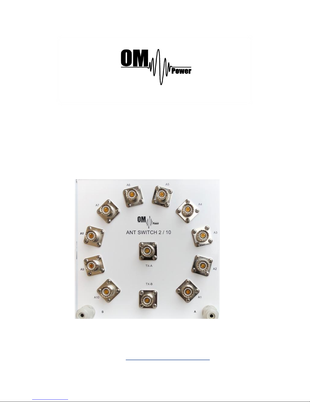
The antenna switch OM SW 2/10 is designed for remote antenna switching. It
allows to connect one of maximally ten antennas to one of two common antenna
ports TX-A and TX-B (outputs).
Antenna switch OM SW 2/10 was designed to cooperate with OM Power
automatic power amplifiers OM2200A, OM2500A, OM4000A and the
OM SW 2/10+, which is equipped with BCD decoder cooperating with
OM2000A+ and OM4001A. It is possible to produce antenna switch with
combination of OM SW2/10 and OM SW 2/10+ (one side controlled with BCD
code)
Of course, the antenna switch OM SW 2/10 and OM SW 2/10+ can be used
independently from OM Power amplifiers, with various controllers.
Features
Selecting one of maximum10 antennas
Characteristic impedance is 50 ohm , frequency range up to 60 MHz
Power rating - up to 5kw continuous carrier
Teflon (PTFE) insulated SO239 connector
Excellent VSWR and crosstalk isolation
Only 20 ms switching time between ports
Compatible with OM Power automatic amplifiers, without need of any
additional devices.
Compatible with any band decoder with 12V source voltage
Page 3
3
Compatible with Yaesu BCD code ( 5V logic)
Unused antenna can be grounded as needed , opened, or loaded with
characteristic impedance
Dust and rain protected
Easily mounted on the wall or tower
The antenna switch is intended to be used either inside or outside
Connecting the switch OM SW 2/10
Antenna switch OM SW 2/10 can be
connected directly to the automatic
power amplifier OM2200A,
OM2500A, OM4000A or other band
decoders and antenna selectors
providing +12 to +15 volts to select
an antenna. Consumption is 100 mA.
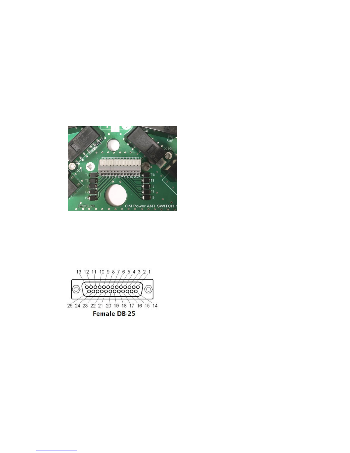
Terminals 1 to 10 on antenna switch
should be connected to the OM Power
automatic amplifier, antenna control
connector (ANT & BPF SW), or other
type of band decoder. Connect the
GND terminal to the ground of your controller!
Configure your automatic power amplifier or band decoder to activate the
appropriate output for the desired antenna on each band!
ANT and BPF SW connector on OM2500A, OM4000A
1. antenna port 1
2. antenna port 2
3. antenna port 3
4. antenna port 4
5. antenna port 5
6. antenna port 6
7. antenna port 7
8. antenna port 8
9. antenna port 9
10. antenna port 10
11. COMMON port of ANT SW – connect +12V external power supply
12. NC
Page 4
4
13. GND - connect-12V terminal of external power supply
Connecting the switch OM SW 2/10+
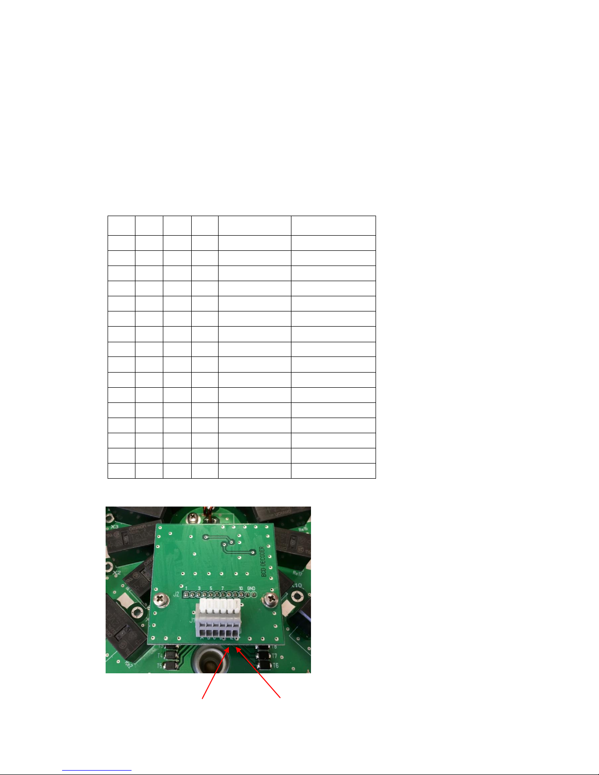
Antenna switch OM SW 2/10+ is designed for OM Power amplifier OM2000A+,
OM4001A and can be directly controlled without any additional device, or other
type of BCD decoder. Selection of required antenna port is controlled with BCD
code (5V logic compatible with YAESU BCD code).
Antenna BCD code table
D C B A Logic value
Antenna port
0 0 0 0 0
UNDEFINED
0 0 0 1 1
ANT 1
0 0 1 0 2
ANT 2
0 0 1 1 3
ANT 3
0 1 0 0 4
ANT 4
0 1 0 1 5
ANT 5
0 1 1 0 6
ANT 6
0 1 1 1 7
ANT 7
1 0 0 0 8
ANT 8
1 0 0 1 9
ANT 9
1 0 1 0 A
ANT 10
1 0 1 1 B
UNDEFINED
1 1 0 0 C
UNDEFINED
1 1 0 1 D
UNDEFINED
1 1 1 0 E
UNDEFINED
1 1 1 1 F
UNDEFINED
TERMINAL CONNECTION
Connect terminals A,B,C and D on
the antenna switch to the ANT/BPF
connector on the OM2000A+ ,
OM4001A power amplifier!
(Connector OM2000A+ ANT/BPF
see below) - Connect 12V terminal
to the ground (PIN 6 or 7) and +12V
terminal to pin 8 of ANT/BPF
connector!
-12 V DC +12 V DC
Page 5
5
Configure your automatic power amplifier or band decoder to activate the
appropriate output for the desired antenna on each band.
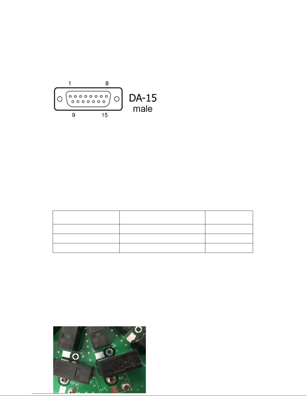
OM2000A+ , OM4001A ANT / BPF Connector - D-sub 15 male
Pin 1 - ANT data D - output BCD code - bit 3 for antenna switching
Pin 2 - ANT data C - output BCD code - bit 2 for antenna switching
Pin 3 - ANT data B -- output BCD code - bit 1 for antenna switching
Pin 4 - ANT data A - output BCD code - bit 0 for antenna switching
Pin 5 - Not connected
Pin 6 - GND
Pin 7 - GND
Pin 8 - +12V 100mA - output supply maximum 100mA for antenna BCD decoder, usable for
supply external antenna switch OM SW 2/10+
Cable length and wire size
If the antenna switch is located some distance from the power amplifier or controller,
it is necessary to use a cable of the appropriate length and wire size.
Cable length ( m / ft )
Conductor Cross-section(
mm2)
AWG
100 / 300
0,14
26
200 / 600
0,25
24
300 / 1000
0,5
20
We recommend to use a shielded cable with a shield used as an added ground lead to
reduce voltage losses. Connect one end of the cable to the terminals of the antenna
switch and the other end to an appropriate connector on your OM Power automatic
amplifier or controller.
OM SW 2/10 requires 2 cables with eleven conductors (ten antennas plus
return/ground).
OM SW 2/10+ requires 2 cables with six conductors (A B C D ports, +12V and
ground). It is convenient to use shielded 8 wire (four pair) cable and two – two wires
parallel for 12V supply.
Unused antenna termination
Unused antennas are connected through
relay to terminal X (See schematic of
antenna switch). If needed, based on
configuration of the antenna system, it is
possible to leave port X unconnected,
connected to the ground or loaded with a
Page 6

6
characteristic impedance (for example when it is connected to the thriplexer).
Usually, antenna switches are delivered with unconnected X ports.
SPECIFICATIONS
Frequency range: ................................................................................ 1.7 - 54 MHz
Characteristic impedance: .......................................................................... 50 ohm
Number of radio ports: .......................................................................................... 2
Number of antenna ports: ................................................................................... 10
Supply voltage: ................................................................................+12 to +15V DC
Selection of port: ......................................................... BCD code or DC 12V select
Consumption: ........................................................................................ max. 100mA
Connectors : ...................................... ............................ SO239 (N type on request)
SWR: (depends on selected port – the worst case) 1.8 MHz: < 1.00 : 1
14 MHz: < 1.02 : 1
28 MHz: < 1.04 : 1
50 MHz: < 1.12 : 1
Isolation TX-A to TX-B :
Next two ports 1,8 MHz: > 80 dB
14 MHz: > 65 dB
28 MHz: > 60 dB
50 MHz: > 54 dB
Others ports 1,8 MHz: >100dB
14 MHz: > 88 dB
28 MHz: > 80 dB
50 MHz: > 72 dB
Insertion loss: (typical) 1.8 MHz < 0.01 dB
14 MHz < 0.02 dB
28 MHz < 0.03 dB
50 MHz < 0.05 dB
Power rating : ( depends on antenna SWR) up
to 30 MHz SWR <1.2 :1......................................... < 5 KW
SWR <1.5 : 1 ....................................... < 4 KW
SWR < 2 : 1 ......................................... < 3 KW
SWR < 3 : 1 ......................................... < 2 KW 50
MHz SWR <1.2 :1......................................... < 3 KW
SWR <1.5 : 1 .................................... < 2,5 KW
SWR < 2 : 1 ......................................... < 2 KW
SWR < 3 : 1 ...................................... < 1,5 KW Operating
temperature range : ...................................................... -30 .. +60 C
Dimensions: ...................W 210mm (8,27") x H 120 mm (4,7") x D 210 mm (8.27")
Weight ....................................................................... 1.56 kg ( 3,44 lbs )
 Loading...