

Page 1
Instruction Manual
OM3006
50 MHz POWER AMPLIFIER
OM POWER, s. r. o. 930 30 Báč 126
SLOVAKIA
Page 2

Important safety instructions:
The amplifier contains high voltage circuits. Never turn the amplifier on
without the upper lid in place.
The OM3006 amplifier is not to be used in a wet or humid environment nor
to be exposed to rainfall.
The amplifier must be installed in such a way that free flow of hot air from
the tube is allowed. The amplifier must not be installed in a constrained
surrounding (i.e. tight shelves etc.)
During long operation the upper lid and the vent grid of the amplifier can
reach high temperatures that can cause burn injuries. Do not touch these parts
of the amplifier during operation.
The amplifier must be grounded during operation.
During operation the amplifier must be installed in such a way that the rear
power supplies are accessible.
The amplifier can be operated only if both supply cables are connected.
OM3006 reaches optimal parameters when it is connected to 2 phases.
Do not turn the amplifier on without having connected the antenna.
A hazardous HF voltage may built up on the antenna connector after turning
the amplifier on with no antenna connected.
Before opening the upper lid of the amplifier make sure that both power
supplies have been disconnected for at least 5 minutes allowing the
electrolytic capacitors to discharge fully. Never turn the amplifier on without
the upper lid in place.
Make sure that all screws holding the case together are properly in place and
tied before carrying the amplifier by the handles.
The amplifier is an A category product. In a household it can influence other
electric appliances. In such cases the user is to take proper actions to mitigate
this disturbance.
Page 3

General description of the OM3006 50 MHz Amplifier
The linear amplifier OM3006 is designed for 50 MHz amateur bands from 50 till 52 MHz
and all modes . It is equipped with a ceramic tetrode GU78b.
Specification of OM3006 :
Frequency coverage: amateur bands 50 – 52 MHz
Power output: 3000 W in SSB and CW , RTTY, AM and FM
Drive Power: usualy 40 to 60 W for full Output Power
Input impedance: 50 Ohm VSWR < 1.5 : 1
Output amplification: 17 dB
Output impedance: 50 Ohm unbalanced
Maximum output SWR: 2:1
SWR protection: automatic switching to STBY , when reflected power is 350W or higher
Intermodulation distortion : 32 dB below nominal output
Suppression of harmonics: < -50 dBc
Tube: GU78b Ceramic tetrode
Cooler : Centrifugal blower + axial blower
Power supply : 2 x 230 V - 50 Hz one or two phases
Transformers: 2 pcs of toroidal transformer 2,5 kVA
Protection circuits: - SWR too high
- Anode current too high
- screen current too high
- grid current too high
- Mistuning of power amplifier
- Hot switching protection
- Soft start for protecting your fuses
- “switch –on blocking “ at opened amplifier
Bar graph indications: - Power output – bargraph 50 LED
- reflected power – bargraph 20 LED
- screen current ( Ig2 – bar graph 10 LED )
- anode voltage, anode current, tuning – bargraph 30 LED
LED indicators : grid current ( Igl – 2 LED )
WAIT – preheating of tube (180 sec )
STBY - standby
OPR – operating condition
FAULT – failure , switching off for abt. 2 sec
Parameters: 485 x 200 x 455mm (width x height x depth)
Weight: 32 kg
Page 4
General Description of OM3006 POWER AMPLIFIER
HF PART
In this amplifier a tetrode GU 78b is used in a grounded-cathode circuit (input into control grid). This
amplifier achieves excellent linearity by the voltage stabilization of the control grid bias and the screen
voltage. The power input is given to the control grid, using a broadband input circuit with an input
impedance of 50 Ohms. This adaptable input circuitry ensures a good input SWR better than 1.5:1 on
all short-wave bands.
The output of the amplifier is a Pi-L circuit. The ceramic capacitor for TUNE and LOAD are divided.
This enables the amplifier to be tuned exactly and makes it possible to easily return to the previously
set positions after band change.
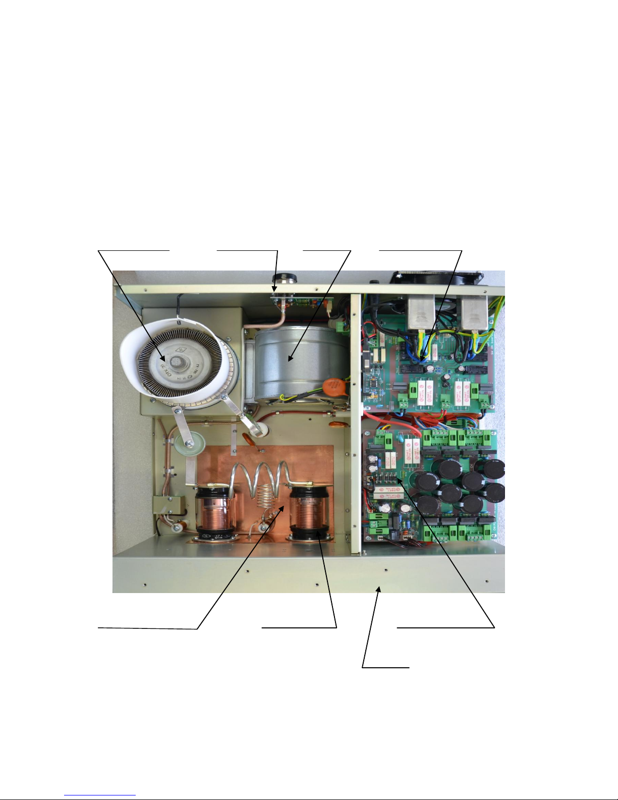
Top view on the opened OM3006
Tetrode GU77B PWR meter Blower switch -on board
Output Pi-L Circuit Tuning capacitor Power supply board
subpanel
Page 5
POWER SUPPLY
Power supply of the amplifier is effected by two 2,5 kVA toroidal transformers. A soft start is
realized with the help of relays and resistors.
The high anode voltage consists of 8 times 425 V and 2A. Each of them has its own rectifier and filter.
In the high voltage circuit safety resistors are employed to protect the amplifier against overload.
The source for screen grid is stabilized by a paralell stabilizator with BU508 transistors and delivers a
voltage of 360V at 100mA.
The -120V for the control grid is stabilized by means of zener diodes.
SAFETY DEVICES
Control and monitoring circuits ensure control and safety of the circuits of the device during
malfunction of the PA. They are placed on the Control board, which is located on the subpanel.
Putting the power amplifier into operation
Coaxial cable
The output of the transceiver is to be connected with the input of the amplifier via RG58 or similar
cable. For the connection between the power amplifier and the antenna RG213 or similar coaxial
cable suited for this high power is to be used. For INPUT and OUTPUT PL-259-sockets with Teflon
isolation are used.
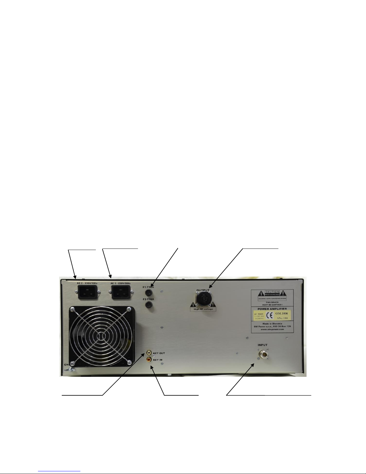
Mains plug1 Mains plug2 Fuses OUTPUT - 7/16 Connector
KEY OUT KEY IN INPUT- N connector
Rear view of the amplifier
Page 6

Control cable
With the control cable ensures switching from reception to transmission. The cable is shielded. On the
side of the power amplifier a CINCH-socket is used. On the side of your transceiver you have to use a
socket suitable for this transceiver. During transmitting the middle pin is connected to the ground.
The relays of the OM3006 have to be switched earlier than HF is applied (cold switching).
Modern transceivers have a time delay between PTT switching and power output.
If you are using and older transceiver or transmitters without time delay we recommend to connect the
PA in such a way that the transmit/ receive switch is connected with the KEY IN socket of the
amplifier. The KEY OUT socket is to be connected with the PTT socket at the transceiver.
The amplifier is equipped with two safety devices, which ensure that the Output relay is not switched
under power mistakenly (hot switching).
MAIN SUPPLY:
The amplifier is connected to the mains with 2 cables with an EURO end. Each cable is to be
switched to another phase of your main supply system! Both of them have to be able to deliver a
power of 2.5 kVA !
If you use only one phase, you have to connect both cables to this one phase ! Your main supply
has to be able to deliver 3,5 kVA on this one phase! In this case the power amplifier can’t
deliver full output!
ATTENTION:
In each case the power amplifier has to be connected
to your main supply system with the 2 cables!
Normally the amplifier is used at 2 phases. If there is
only one phase connect the 2 cables to this one!
Grounding
The amplifier has to be grounded properly! Connect the screw on the rear panel of the amplifier to
your local grounding system with a copper-cable, use a cross-section of 4 mm2 at least.
Connect your transceiver to the same grounding system of your shack carefully!
If you use a power amplifier with higher output you have to be aware that your grounding system
works properly. All parts have to be grounded to the same system. Use short cables and make sure
that there are good contacts! Otherwise you run the risk of damaging your equipment, having
problems with TVI/BCI or your signal may be distorted.
Page 7

Cooling
The centrifugal blowers provide the necessary cooling of the amplifier, even during long contests. The
main blower is activated by switching the PA on and it is turned off when after-cooling is finished
(approx. 1-5 min after switching off the PA depending on the temperature of the tube). The
supplemental fan is turned on depending on the temperature of the air exiting from the amplifier. It is
switched on at 70°C and switched off at 60°C.
Operation
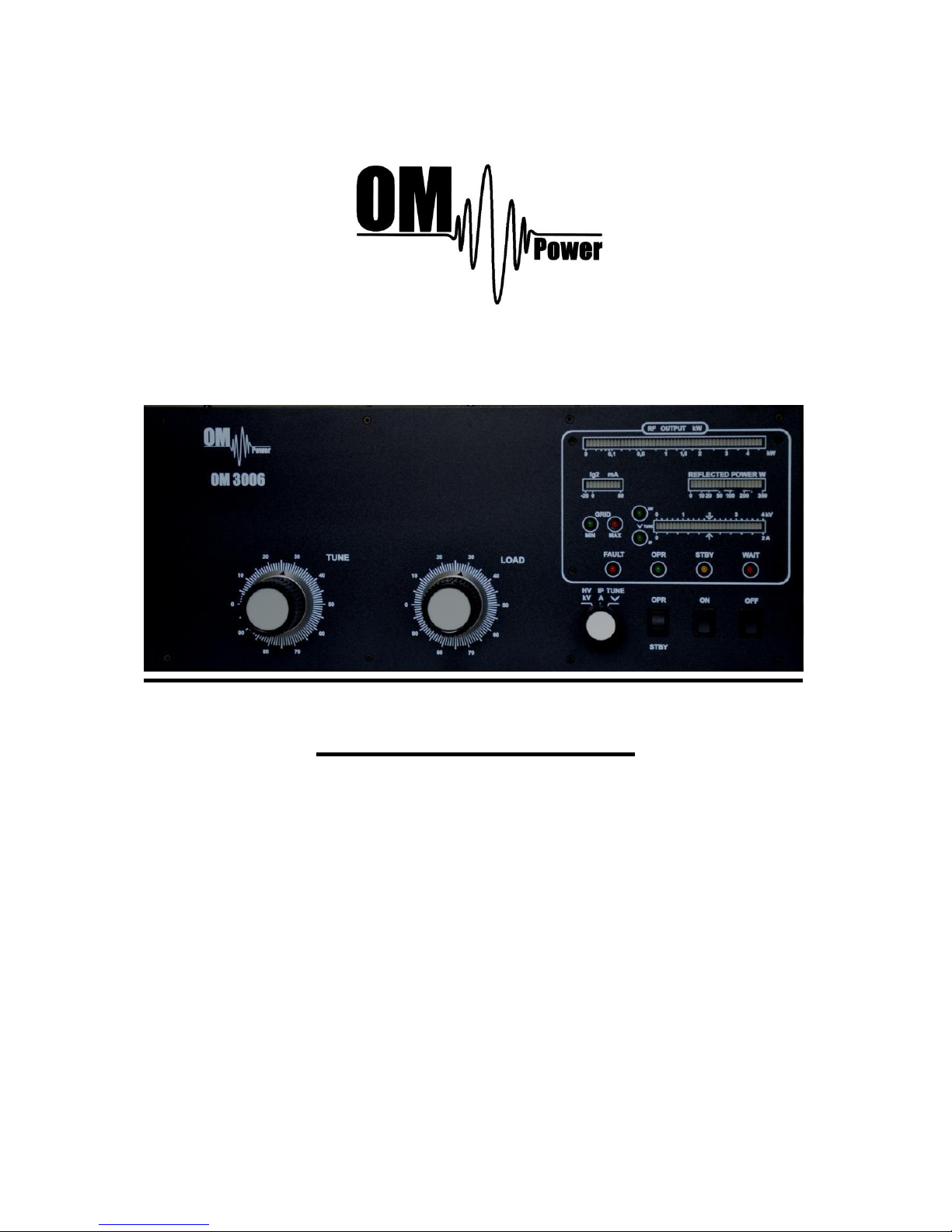
Operating elements (see photo of front panel)
TUNE - Anode capacitor for tuning, tuning of higher frequencies to "0",
lower frequencies to „100“.
LOAD - Output capacitor tunes antenna load resistance to amplifier.
Capacity is low at „0“ and high at "100" on the scale.
OFF - You switch off the amplifier by pressing this button.
ON - You switch on the amplifier by pressing this button.
Heating of tube is on and after 3min of delay the amplifier will be
ready for operation.
OPR/STBY - „OPERATE“ you will be ready for operation.
At STBY, if WAIT-LED is on or the amplifier is off your transceiver is in
bypass-mode directly connected to antenna. Maximum 400Watts !
RF OUTPUT - Bar graph – shows output power .
REFLECTED POWER - Bar graph – shows reflected power of the antenna. 350W
maximum or amplifier switches to STANDBY-mode
Ig2 bargraph – measerus the currency of the second grid in the range from -20mA to
+80mA
HV/IP/TUNE bargraph – measure the anode voltage, anode currency or tuning of the amplifier
TUNING
The OM3006 amplifier is operated in class AB. Thus it’s possible to obtain a maximum output
power at an excellent linearity. For this purpose the amplifier has to be tuned carefully.
The operation of a mistuned PA will cause malfunctions, the increase of grid current (the GRIDMAX-LED will light up) and problems with TVI/BCI.
The grid-current is shown with 2 LED diodes. It’s normal if the green LED is flashing or may be
shining a little bit during peak operation. If you overload the amplifier the output power increases the
grid current at very small rates and the red GRID-MAX-LED is shining and the safety devices switch
the PA to STBY, you have overloaded the amplifier and must decrease the output.
Page 8
In SSB you will have a good output power if the green LED lights up a bit. The current of screen
grid is measured and shown in a Bar graph indicator. The amplifier has to be tuned in such a
way that the current is between - 20 mA to +50 mA. At currents beyond these values the
operating point will be shifted and IM-products will be rapidly increased. If a value of + 70mA is
exceeded, the safety devices will switch the amplifier to STBY mode.
Tuning instruction :
Please note :
Before starting tuning you have to check if the right antenna or a 50 Ohms
load resistance is connected at the antenna output !
Switching on the amplifier:
put the switch at the multimeter to HV position
put the OPR/STBY switch to STBY position
press the „ON“ button
The amplifier is prepared for operation with the following steps:
the toroidal transformers are switched step by step.
the blower of tube is switched on.
the multimeter bargraph measures the high voltage; the normal value is 3.4 kV
the WAIT LED lights up
After switching on you have to check the functioning of the blower. Air must be blown out of the
ventilating apertures above the tube. ( If there is any failure you have to press the „OFF”-button
immediately !)
Heating the tube takes about 150 seconds. After this time the WAIT LED goes out and the amplifier is
ready for operation.
Tuning the amplifier to an output of 3000 W
1. Switch BAND, TUNE and LOAD to the position according to the table:
Band
Tune
Load
50,5 MHz
The tuning table available to you is made by using a dummy load! Each amplifier will have other
values depending on used frequency and antenna! Make your own list for your own antennas! Use
tuning position (see later)!
2. Reduce the power output of your transceiver to the 0.
3. Switch OPR/STBY to „OPR“ position (OPR LED lights up)
4. Choose TUNE position of multimeter.
5. Switch the PA to CW and increase driver power to 10W (OUTPUT power will be PA abt.
500W)
Page 9

Please note!
If the input power is higher than 15 W and the power amplifier is not correctly tuned, the safety
devices will switch to STBY.
After switching the amplifier to PTT, the amplifier will automatically reset and switch back to OPR
mode after approximately 2 seconds.
6. Set TUNE in such a way, that the TUNE-LED lights up maximum left.
7. Set LOAD in such a way, that the TUNE LED on the TUNE scale lights up under
the “V” sign. If it is possible to obtain the LOAD in 2 positions, set the position
that is father to the right.
8. Repeat tuning several times according to 6 and 7.
9. Increase the input power until an output power of approximately 2000 W is reached.
10. Repeat steps 6 and 7
11. Set TUNE to maximum output power
After this procedure the amplifier is tuned correctly and ready to give 2000 W output power in all
operation modes. At optimal tuning and full output power a positive 50mA voltage goes through the
second grid. . If less output is desired you can simply decrease the load of the transceiver.
Please note: Should the amplifier demonstrate any malfunctions during
tuning or should it not behave in accordance witch the description,
interrupt the tuning procedure immediately and check the amplifier!
Be sure to have not done any mistakes in choosing bands or TUNE/LOAD
values!
Be sure that SWR is not higher than 1:2 and input power is LOW!
After cancelling human mistakes you will be able to work for long time with
this amplifier!
Page 10

Indication of fault conditions
OM3006 has the following indication LED on the front panel:
GRID MIN - indication of first gird currency
GRID MAX - max. First grid currency exceeded
HV - measuring of anode voltage by bargraph
IP - measuring of anode currency by bargraph
FAULT - fault
OPR - amplifier in operation mode
STBY - amplifier in standby mode
WAIT - heating of tube after switichg on the amplifier
Should a fault condition appear during the tuning or operation of the amplifier the safety
circuits of OM3006 will react. The amplifier will be turned to STBY mode. After approx. 1
sec the control ciruits will switch the amplifier back to OPR. If the fault will repeat 3 times
after each other the control circuits will turn the amplifier to STBY. Brining the amplifier to
OPR is enabled by using the OPR/STBY switch.
After the reaction of safety circuits the FAULT LED will be lit up for approx. 5 sec
depending on the nature of the fault.
Flashing LED signalizes:
IP - anode currency exceeded
HV - low anode voltage
FAULT - reflected output exceeded
GRID MAX - first grid currency exceeded
- screen grid currency exceeded
GRID MAX + HV - maximum input power exceeded
GRID MAX + IP - zero output power during tuning
HV + IP - tuning fault, incorrect tuning of the Pi-L output circuit
In case your OM3006 amplifier is not working, please contact the
manufacturer,
 Loading...