

Page 1
1
MADE IN SLOVAKIA
OM Power, s.r.o. 93030 Báč 126,
SLOVAKIA
Contact : +421 905 321 410
e-mail: [email protected]
WWW.OM-POWER.COM
Instruction Manual
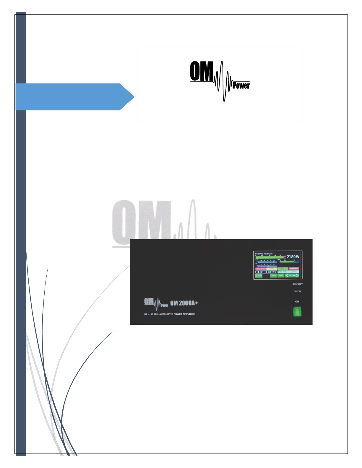
OM2000A+
SHORTWAVE PLUS 50 MHz
POWER AMPLIFIER
FCC ID: X8NOM2000A
Page 2

2
Thank you for purchasing this new model of the OM Power’s RF power amplifiers line for HF and 50
MHz amateur radio bands. You now own, the OM2000A+, an automatic unit with no knobs, no rotary
switches on the front panel, just two small switches and one large touch display.
Smart design, modern conception, high reliability is the result of OM Power’s development and many
years of experience with overall solutions and special attention with the design of the protection circuits.
This product is covered by two years of warranty on the amplifier itself and one year for the tube.
We wish you will have many years of trouble-free use of this equipment, lots of fun and successful
contacts in the world of amateur radio.
The Array Solutions and
OM Power Team
Page 3
3
TABLE OF CONTENTS
1. GENERAL INFORMATION ....................................................................................... 5
1.1. Introduction ………………………………………………………………. 5
1.2. Specification ………………………………………………………………. 5
1.2.1. Parameters …………………….…………………………………. 5
1.2.2. Protection Circuits ………………………………………………………. 6
1.2.3. Features ………………………………………………………………. 6
1.2.4. The Advantages of OM2000A+ …………………………………………… 6
2. SAFETY INSTRUCTIONS ………………………………………………………. 7
3. GENERAL DESCRIPTION ………………………………………………………. 8
3.1. HF part …………………………………………………………………. 8
3.2. Power Supply …………………………………………………………………. 10
3.3. Safety Devices …………………………………………………………………. 10
4. INSTALLATION ………………………….…………………………. 10
4.1. Grounding ……………………………………………………. 11
4.2. Coaxial Cable ……………………………………………………. 11
4.3. Control Cable ……………………………………………………. 12
4.4. Cooling ……………………………………………………. 12
5. OPERATION ……………………………………………………………. 13
5.1. OM2000A+ Front Panel ……………………………………………. 13
5.2. OM2000A+ Control …………………………………………………… 14
5.3. Preparing for operation ………………………………………….……… 21
5.4. Operation mode ………………………………………………………. 28
6. MAINTENANCE ……………………………………………………. 32
6.1. Indication of Fault Conditions ………………………………………… 32
6.2. Fuse Replacement ……………………………………………..……. 34
6.3. Tube Replacement ………………………………………………..…. 34
Page 4

4
6.4. Cleaning …………………………………………………... 34
7. APPENDIX ……………………………………………………………. 34
7.1. Primary AC selection …………………………………………………… 34
7.2. Removing the HV Transformer ……………………………………………. 36
7.3. Controlling OM200A+ with FLEX Radio Series 6xxx ……………………… 37
7.4. OM2000A+ Remote Control ………………………………………………. 39
7.5. Remote Control using own public IP Address ........................................ 44
7.5.1. Changing OM2000A+ connection settings ............................................ 44
7.5.2. Setting up in the Remote software .......................................................... 45
7.5.3. Remote Control without own IP Address, behind a router ..................... 46
7.6. OM2000A+ firmware upgrade …………………………………….………. 47
7.7. Icom connection with OM2000A+ ………………………………...……… 53
7.8. Yaesu plus BPF plus ANT Switch connection with OM2000A+ ………. 54
7.9. Control panel connectors pin-out ……………………………………..…… 55
7.10. Block Diagram of the OM2000A+ Power Amplifier ………………………… 59
7.11. Troubleshooting …….………………………………………….……………. 60
Page 5
5
1. GENERAL INFORMATION
1.1. Introduction
he OM Power model OM2000A+ is designed for all short wave amateur bands from 1.8 to 29.7
MHz (including WARC bands) plus 50 MHZ and all modes. It is equipped with a ceramic
tetrode FU-728F.
1.2. Specification
1.2.1. Parameters
Frequency Coverage Amateur Bands 1.8 – 29.7 MHz including WARC + 50 MHz
Power Output 1500+ W in SSB/CW on HF bands, 1500 W in CW/SSB on 6m
1500 W in RTTY
Input Power Usually 40 to 60W for full Output Power
Input Impedance 50 Ohm, VSWR < 1.5 : 1
Power Gain 15 dB
Output Impedance 50 Ohm unbalanced
Maximum Output SWR 3 : 1
SWR protection Automatic switching to STBY, when reflected power
is 350W or higher
Intermodulation distortion 32dB below nominal output
Suppression of harmonics < -50 dBc ; <-70dBc on 50 MHz
Tubes FU-728F Ceramic tetrode
Cooler Centrifugal blower + Axial blower
Power supply switchable 220V, 230V, 240V, 50/60 Hz or other primary
voltages…. (200V 50/60Hz for Japan)
Transformers One toroidal transformer 3kVA
Dimensions 390 x 195 x 370 (width x height x depth)
Weight 24 kg (53 lb)
T
Page 6
6
1.2.2. Protection Circuits
There are several protection circuits used in the amplifier. They are activated when one or
more of next parameters exceed defined values or some unwanted occasion occurs.
• VSWR too high
• Anode current too high
• Anode voltage error
• Screen current too high
• Screen voltage error
• Grid current too high
• Grid voltage error
• Heating voltage error
• Mistuning of PA
• Temperature to high
• Soft start for fuses protection
• “switch-on blocking “ at opened amplifier
1.2.3. Features
The manufacturer implemented some of the company’s newest development results with most
wanted operating and safety features into this new model:
• High level of protection
• Memory for faults and warnings, easy maintenance
• Automatic set-up anode current (BIAS) – no need to adjust manually after changing the
tube
• Three programmable working modes of the centrifugal blower ( turbine ) + axial blower
• Full QSK with silent relay
• Many operational parameters to display
• Easy transport due to detachable HV transformer
• The smallest and lightest 2000 W Power Amplifier on the market
1.2.4. The Advantages of OM2000A+
• Full compatibility with: ICOM, ELECRAFT, KENWOOD, TEN-TEC ORION, YAESU,
Icom, transceive protocol using by MicroHAM devices ( CI-V output ), FLEX
Radios and Anan.
• RF sensitive. The PA is usable also with radios, which doesn´t have CAT (automatic
frequency reading even if no CAT). Possibility of using BAND DATA information.
• Automatic switching between bands. Automatic tuning within the band according to
segments.
• Automatic switching of Band Pass Filter – BAND DATA output compatible with YAESU
radios (BCD code).
• Automatic switching of Antenna switches. The maximum number of antennas is 10,
controlled by BCD output code.
• Remote control possibility (remote software as accessory – no extra price) http://www.om-
power.com/download/HF PA_Manager_
Page 7
7
2. SAFETY INSTRUCTIONS
DANGEROUS HIGH VOLTAGE INSIDE!
The power amplifier is using high voltage up to 3200V DC, which is very dangerous for human
life! Read next safety instructions carefully first, before you will start to install and operate
power amplifier! NEVER VIOLATE NEXT RULES!
NEVER ALLOW CHILDREN to play around PA or to touch power amplifier or connected cables
in working condition, or to push anything into the case holes!
Never turn the amplifier on without the upper lid in place. DO NOT ATTEMPT TO SHORT OR
BYPASS safety switch under upper lid!
The OM2000A+ amplifier is neither to be used in a WET or HUMID environment nor to be
exposed to RAINFALL!
Do not turn the amplifier ON without having connected the ANTENNA or properly rated DUMMY
LOAD! A hazardous HF voltage may build up on the antenna connector after turning the
amplifier on with no antenna or dummy load connected!
Before opening the upper lid of the amplifier make sure that power supply has been
disconnected AT LEAST 10 minutes allowing the electrolytic capacitors to discharge fully.
Disconnect power cord from the outlet!
Any work inside the PA (internal fuses replacement, tube replacement, etc.) can be carried out
only by professionally qualified person!
Page 8
8
CAUTION
The amplifier must be installed in such a way that free flow of hot air from the tube is allowed.
The amplifier must not be installed in a constrained surrounding (i.e. tight shelves etc.). During
long time operation ventilation grid can reach high temperature. Do not touch it!
The amplifier must be properly grounded during operation.
During operation the amplifier must be installed in such a way that the rear side remains
accessible.
The amplifier is an A category product. In a household it can influence other electric appliances.
In such cases the user is to take proper actions to mitigate this disturbance.
Read this manual carefully. Fallow all of instructions during installation and operation to avoid
damage to the amplifier not covered by manufacturer´s warranty! Do not attempt to perform
any change of hardware or software!
3. GENERAL DESCRIPTION
3.1. HF part
his amplifier is using a ceramic tetrode FU-728F in a grounded-cathode circuit (input into
control grids). The OM2000A+ amplifier achieves excellent linearity by the voltage stabilization of
the control grid bias and the screen voltage. The power input is given to the control grids, using a
broadband input circuit with an input impedance of 50 Ohms. This adaptable input circuitry
ensures a good input SWR (better than 1.5 : 1) on all amateur bands.
T
Page 9
9
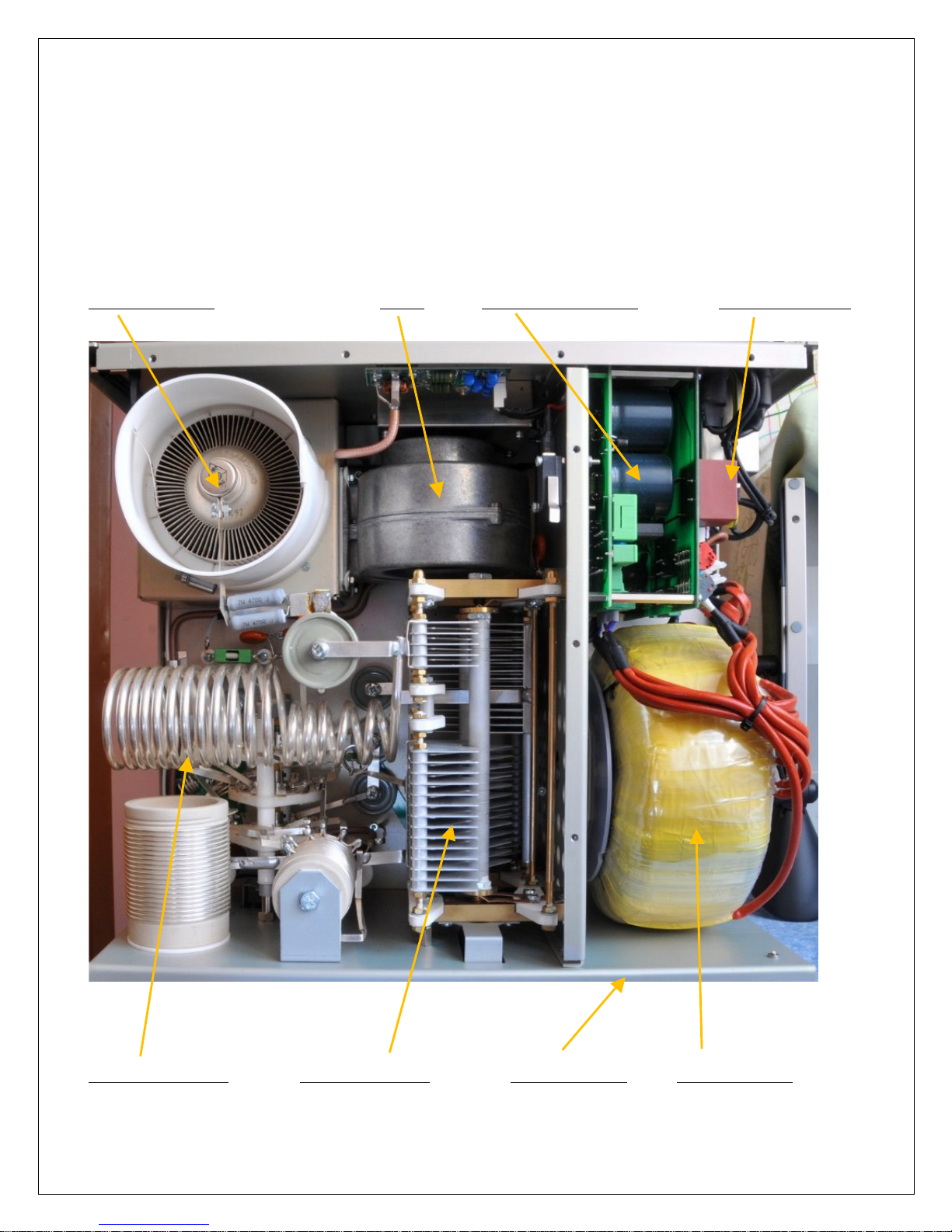
The output of the amplifier is a Pi-L circuit. The ceramic capacitor for TUNE and LOAD are divided.
This enables the amplifier to be tuned exactly and makes it possible to easily return to the previously
set positions after band changes.
Top view on the opened OM2000A+
Tetrode FU728F Blower Power Supply Board Switch-ON Board
Output Pi-L Circuit Tuning Capacitor Front Subpanel HV transformer
Page 10
10
3.2. Power Supply
Power amplifier is using one 3 KVA toroidal transformer. A soft start is provided using relays and
resistors (placed on the switch-ON board). The high voltage is made by combining 4 x 575V AC (total
abt. 3200V DC) @ 1.2A. Each has its own rectifier and filter. In the high voltage circuit, safety resistors
are employed to protect the amplifier against overload (placed on the power supply board).
The separated supply for screen grid is regulated by stabilization with MOSFET and delivers abt. 330V
DC at 100mA. Control grid voltage is also stabilized (-120V DC). Change of stabilized first grid voltage
is controlled by the software (EBS for example).
Primary section of the transformer is adjustable for 230 - 250 VAC. Factory setting is 240VAC.
If the AC voltage in your network is 230 or 250 Volts, you need to set the correct value before
first starting of the PA. See part 7.1. for more information. Other primary voltage is possible on
request (for example 200V 50/60 Hz for Japan).
3.3. Safety Devices
Control and monitoring circuits ensure control and safety during malfunctions of the PA. These are
placed on the Control board, which is located on the chassis subpanel.
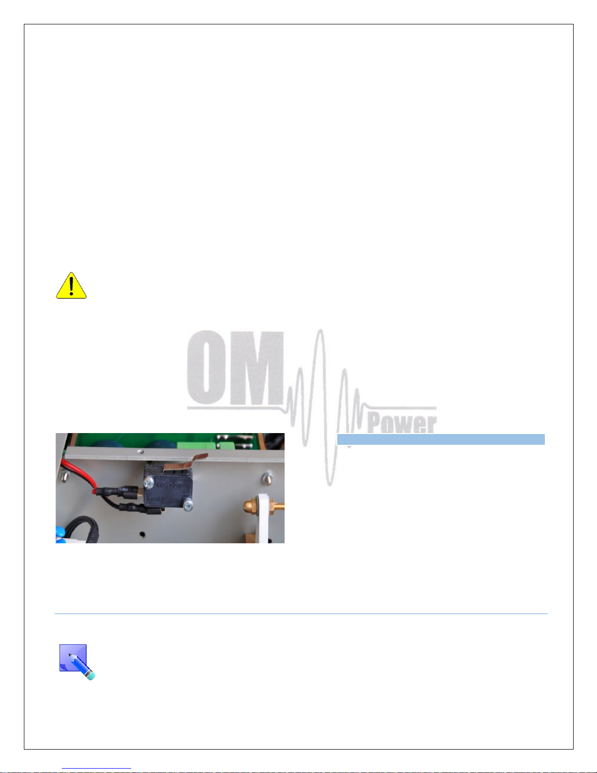
One of the important safety element is mechanical
switch for AC blocking at opened amplifier.
4. INST ALLATION
Read this chapter carefully prior you will start installation. Before unpacking inspect shipping
carton first, if it is not damaged. Keep all of packing parts for possible future shipment. Check
unpacked power amplifier. If you find some damaging, contact your dealer immediately to
keep full warranty.
Page 11
11
During installation go step by step according to the next parts.
4.1. Grounding
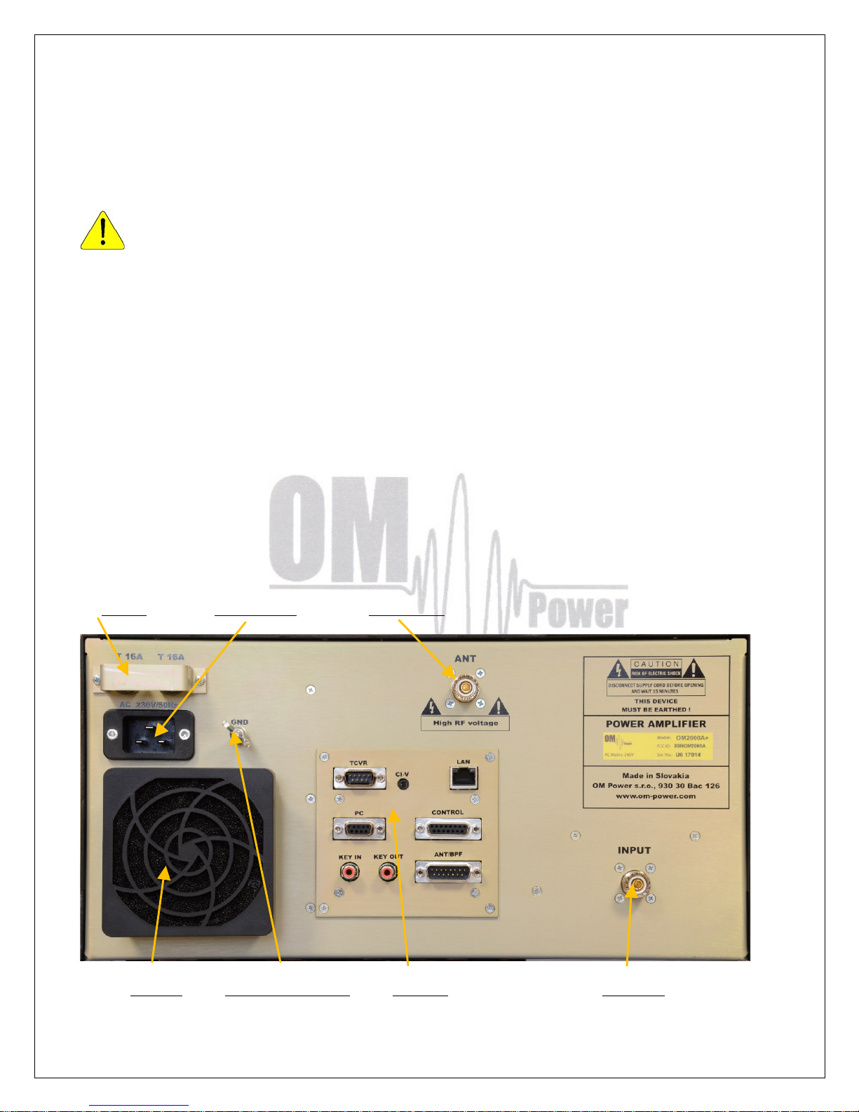
The amplifier has to be grounded properly! Connect the screw on the rear panel of the
amplifier to your local grounding system with a copper cable; use a cross-section of
4 mm2 (AWG 12 ) at least.
Connect your transceiver to the same grounding system of your shack carefully! Use minimum length
cables and make certain that the connections are both physically and electrically sound. With poor
grounding, you may risk damaging your equipment, having problems with TVI/BCI or your transmitted
signal may be distorted.
4.2. Coaxial Cable
The output of the transceiver is to be connected to the input of the amplifier via RG58 or similar cable.
For the connection between the power amplifier and the antenna, RG213 or similar coaxial cable
suited for high power is recommended. At the INPUT and OUTPUT SO-239 sockets with Teflon
insulation are used.
Rier view of the amplifier OM2000A+
Fuses Mains Plug HF Output
Blower Grounding point Control HF Input
Page 12
12
4.3. Control Cable
Control cable maintains TX / RX switching of the PA (TX GND). The cable is shielded. On the side of
the power amplifier a CINCH-socket is used. On the side of your transceiver you have to use a socket
suitable for this transceiver. During transmitting the middle pin is connected to the ground. The relays of
the OM2000A+ have to be switched earlier than HF is applied (cold switching). Modern transceivers
they have a time delay between PTT switching and power output.
If you are using an older transceiver or transmitters without time delay, we recommend
to connect the PA in such a way that the transmit/receive switch (foot switch for
example) is connected with the KEY IN socket of the amplifier. The KEY OUT socket is to
be connected with the PTT socket at the transceiver.
The amplifier is equipped with safety devices, which ensure that the output relay is not switched under
power mistakenly (hot switching).
KEY IN RCA Phono - Input signal PTT switching voltage / current - 5V /2mA)
KEY OUT RCA Phono - Output signal PTT (maximum switching of 30V / 50mA)
See section 7.6. for Control and ANT/BPF connectors PIN-OUT.
Be sure that your power system is correctly wired and properly rated! To use
adequately sized and connected grounding system is also very important!
4.4. Cooling
The amplifier must be installed in such a way that free flow of hot air from the tube is
allowed. Do not obstruct air intake and exhaust areas of the PA.
The centrifugal blower provides the necessary cooling of the amplifier, even during long contests. The
blower is activated by switching the PA on and it is turned off when cooling is finished (approx. 1-5 min
after switching off the PA depending on the temperature of the tube). Blower working mode is
programmable (3 modes). See page 19 for more details.
Page 13
13
5. OPERATION
Before switching PA on, make sure that amplifier is grounded, antenna or dummy load
is connected, and line cord is putted to the outlet. Be sure you selected AC input by 7.1.
Do not turn PA on for at least 2 hours after unpacking it and locating in its operating
location. Especially when amplifier is moved from a cold place to a warm one because
not visible condensation may develop, and this could result in damage to the high
voltage circuits.
We do not recommend to change antenna output during a transmission.
When you decide to have a short operating break, place the amplifier to the standby mode
rather than switch it off.
5.1. OM2000A+ Front Panel
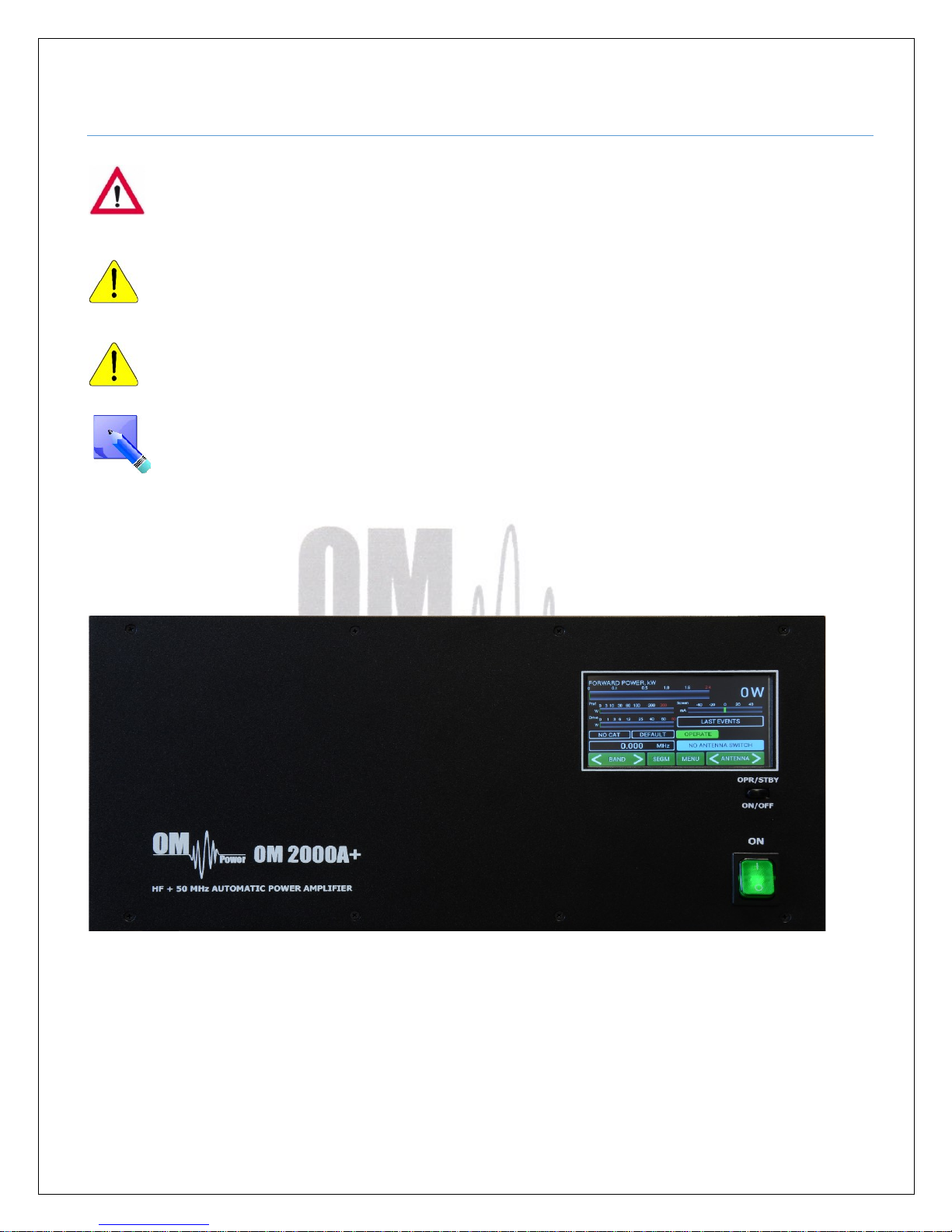
Front panel of the OM2000A is almost empty…There is only touch TFT display accessible plus two
switches.
ON - Main Switch. After turning ON small 12V APU for logic, protection circuits and the display
will be activated. High voltage and RF circuits are still OFF.
OPR/STBY - Short press for switching betwen STBY and OPERATION mode.
ON/OFF - Long press (1 sec.) for switching the PA ON (tube heating first), 2 seconds for PA
OFF.
Page 14
14
5.2. OM2000A+ control
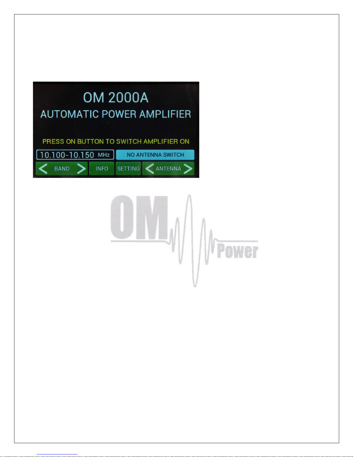
Turn ON the Main switch and the home screen will lights up. In the bottom line touch buttons are
visible
Remember that the home screen is active for some information and settings , while PA is still OFF!
BAND
Touch the left side of BAND button to go down, touch the right site to go up with band displayed above
the button.
ANTENNA
Transmitting antenna choice. Functional ONLY when the antenna switch is programmed and antennas
are defined (see next parts). It allows switching between antennas authorized for the current band. An
external antenna switch is controlled by BCD code at the ANT/BPF output.
INFO
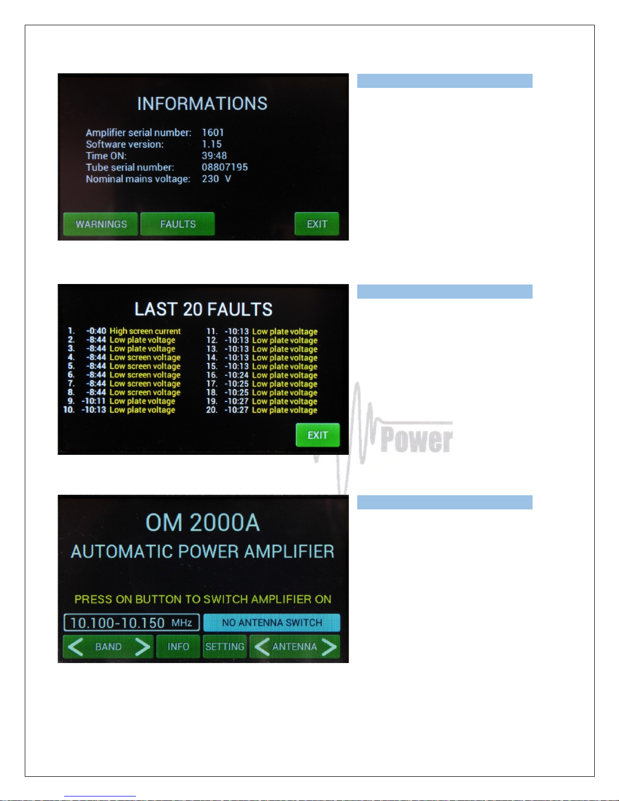
Information display shows basic information about the PA: serial number, software version, time ON,
tube serial number and nominal Main voltage. Some of them manufacturer can requested in case of
any failure, etc.
Page 15
15
Also it provides an overview of the last 20
warnings and faults:
Touch FAULTS.
Press EXIT to go back to the home
screen.
Now press SETTINGS. Display shows
menu which allows to set CAT,
ANTENNA, DISPLAY, EBS, CLEAR user
settings for one or all bands, BLOWER
mode and another INFO.
Page 16
16
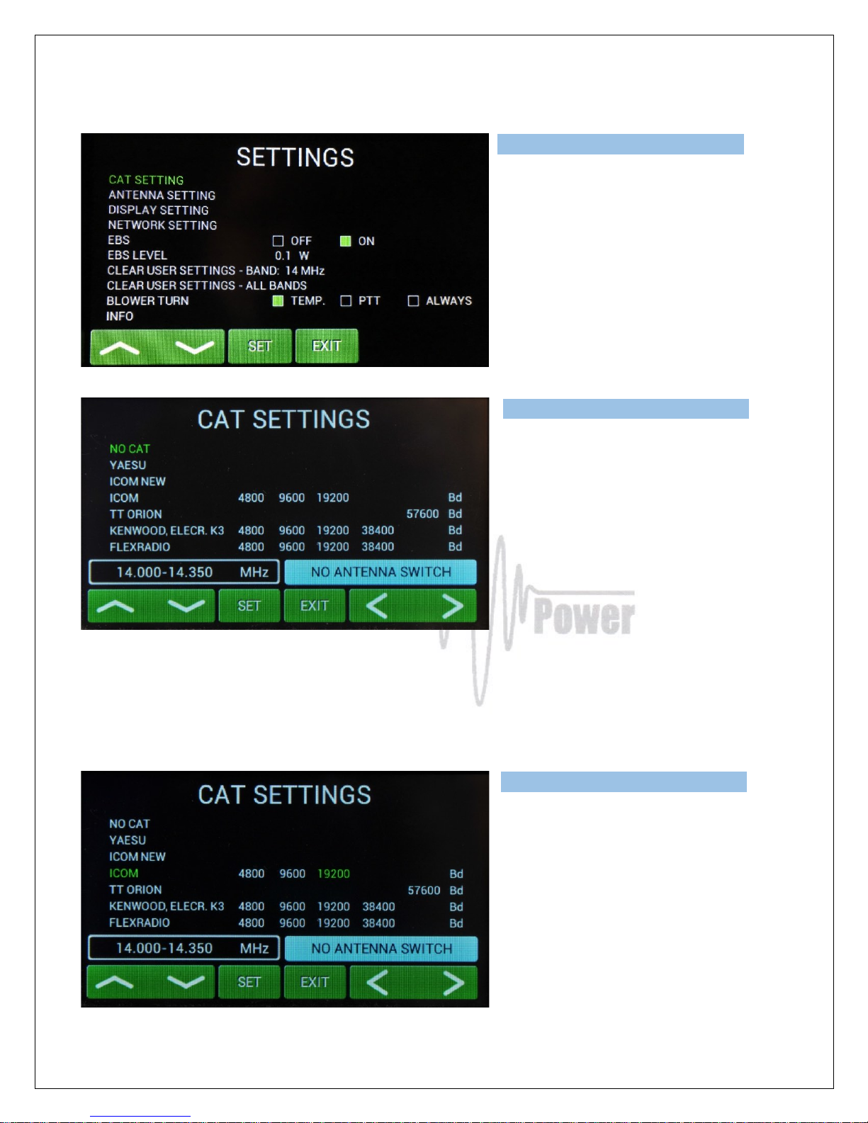
Scroll to CAT SETTINGS (up or down)
and touch SET.
Scroll to your TCVR family (up or down)
and select baud rate (left or right), then
press SET.
Or select NO CAT and press SET.
We recommend to use CAT connection always when possible, because in such a case OM2000A+
has permanent information about the transmit frequency and is immediately ready for transmitting.
With setting NO CAT the OM2000A+ detects transmit frequency from the input signal. With the input
signal frequency changing the PA automatically reacts and tune itself to optimal output parameters.
Tuning takes abt. 1sec. inside the band, abt. 2 sec if band is changed.
If you choose YAESU or ICOM NEW,
after SET pressing you will go to deeper
level which allows you to select specific
type of TCVR. See the following picture
for ICOM NEW selection, for example.
Page 17
17
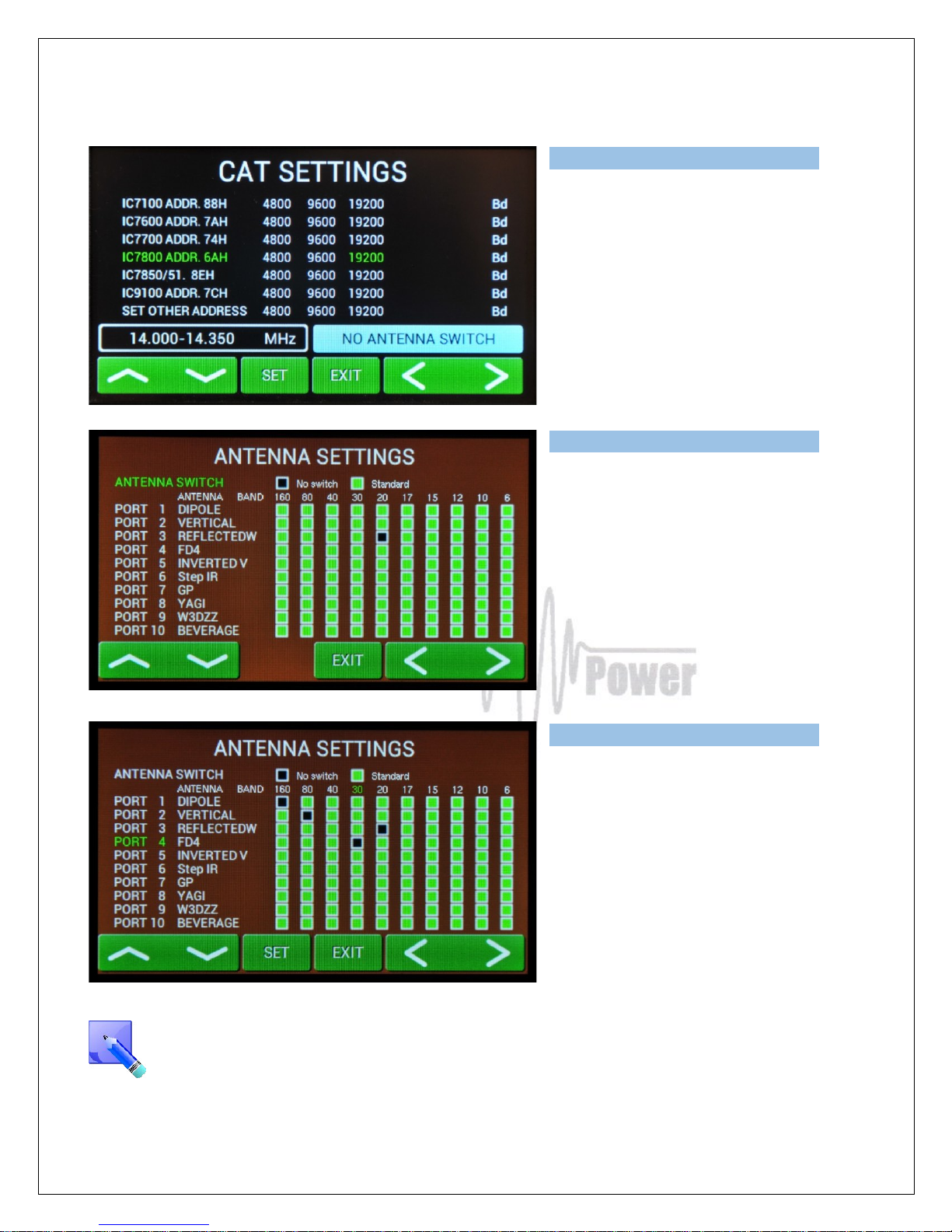
You selected IC7800 addr.6AH and 19200
Bd. Press SET to write to the memory,
then press EXIT to go back to the
SETTINGS possibilities.
“SET OTHER ADDRESS” means that you
must add here a new type of used ICOM
TCVR which is not defined in the table (its
address plus bit rate in Bd) to have
possibility to communicate with it.
Touch ANTENNA SETTINGS. First select
ANTENNA SWITCH (No switch,
Standard). Use left or right arrows. If you
select some switch, 10 ports for different
antennas displays. Generally all of
antennas are allowed in every band
(green squares). To disable some square
select port (up/down), touch SET for
antenna name and then select band
(left/right). Touch SET.
Four types of antenna for four different
bands were disabled.
Black square means disabled
combination.
Press EXIT to go back to SETTINGS
menu.
BCD code (4 bits) is using for automatic antenna and BPF switching (see Antenna/BPF
connector on the Control panel (rear side of the PA). See section 7.8. for Control and
ANT/BPF connectors pin-out.
Page 18
18
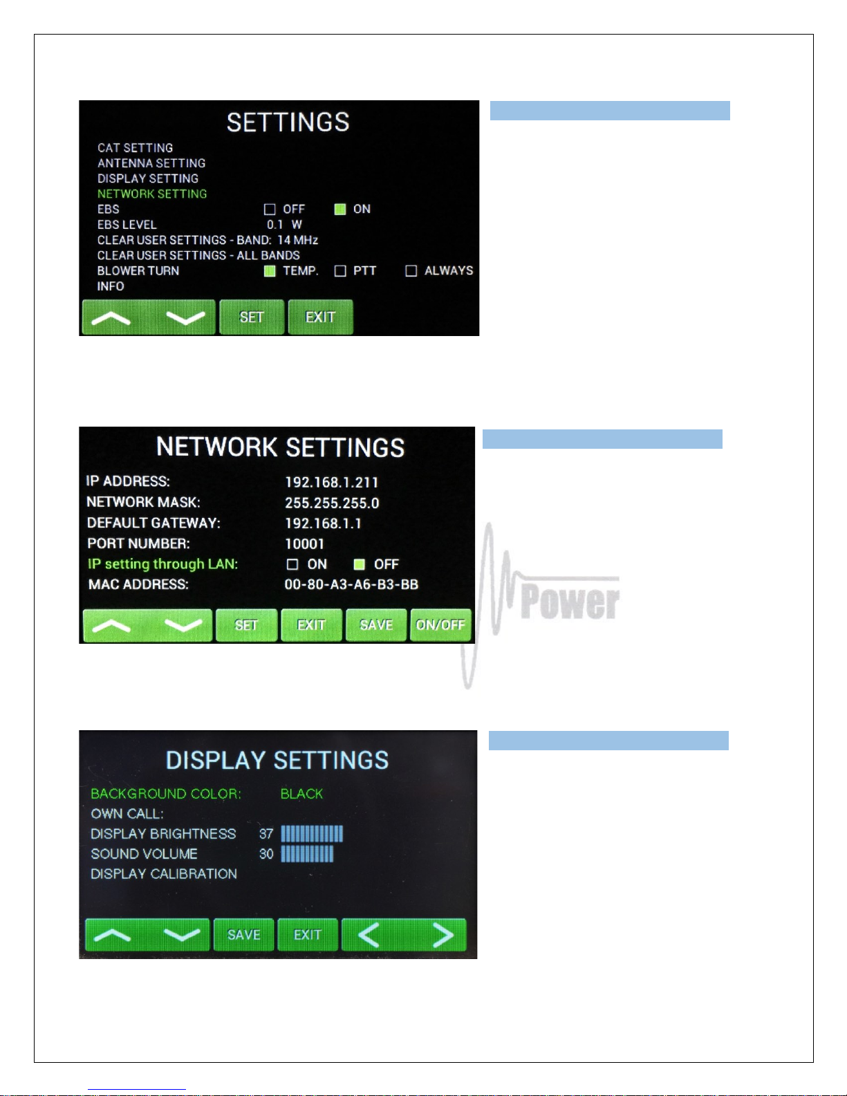
NETWORK SETTINGS is present in
software version 4.01 and above (all
software software releases after May
2017 already includes this feature)
Press SET to enter to this settings.
In the NETWORK SETTINGS submenu
you can adjust all needed parameters for
LAN or WAN connection.
Set IP settings throught LAN to ON when
you want to change this parameter trought
LAN. (see page 44)
Press SAVE to write the changes to the
memory.
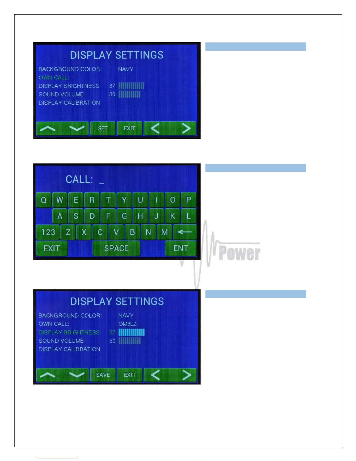
Next SETTINGS position is for display
parameters. First choose the background
color. Scroll on it and choose the color
(left/right).
Press SAVE twice, then scroll to OWN
CALL.
Page 19
19
Press SET for your callsign edit. The
keyboard displays.
Type your callsign and press ENT.
Use next lines and set brightness and
sound volume (use up/down and
left/right). Confirm with SAVE.
Page 20
20
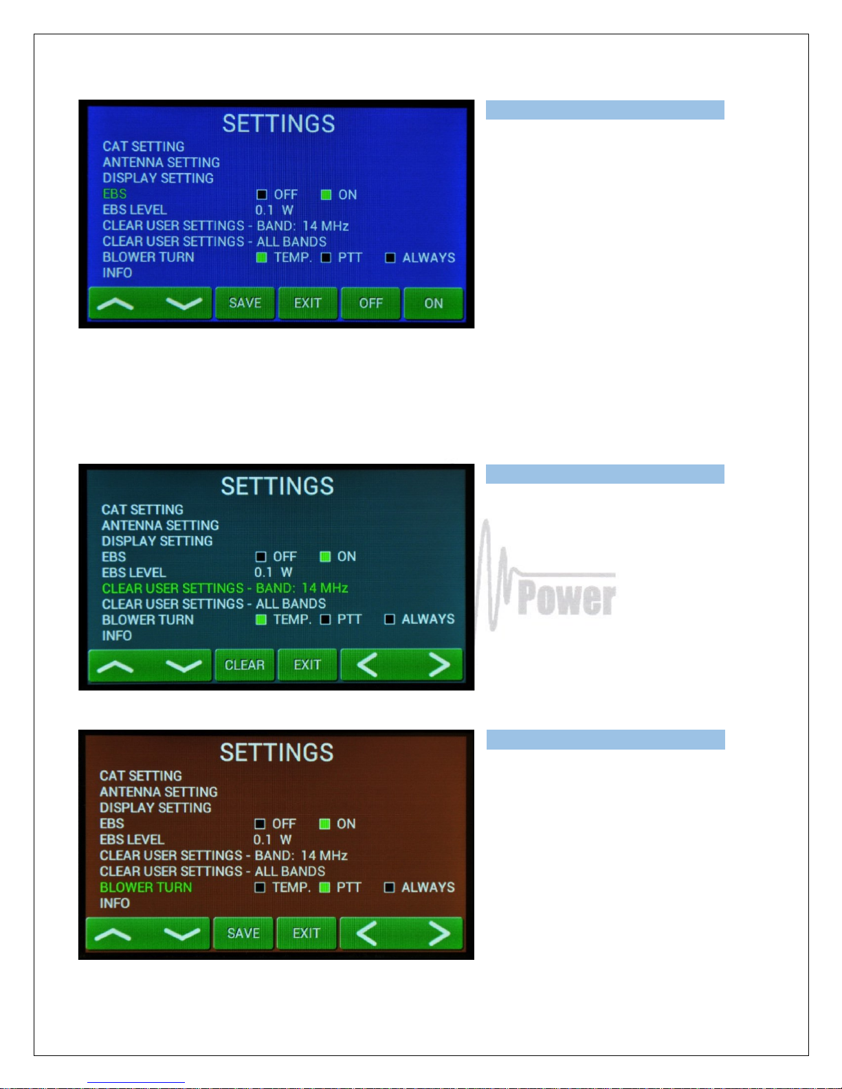
Next lines are for EBS (Electronic Bias
Settting) ON/OFF and for EBS level
selection.
We recommend EBS ON. See next
comment for more details.
Electronic Bias Settings (EBS) is one of significant feature of the power amplifier. It allows to set low
plate current after pressing the PTT regardless of whether you have CW or SSB mode, until RF signal
is no present at the input. At the moment when RF signal comes to the input of PA, bias will
automatically change to its working value.
EBS level means level of the Input power, where EBS starts working. Default EBS value is 0.1 W. We
recommend using EBS ON. Significant accompaniment of used EBS is temperature reducing.
Next two lines allow delete user settings of
antenna tunings for selected band or for
all bands.
Settings in all segments will return to the
factory default values (for 50 Ohms).
In the next line you can define working
mode of the blower. In the first case speed
depends on the temperature (TEMP),
during PTT speed increased to maximum,
ALLWAYS means maximum speed all the
time during PA operation (recommended
for DIGI modes).
Press SAVE to write the mode to the
memory.
Page 21
21
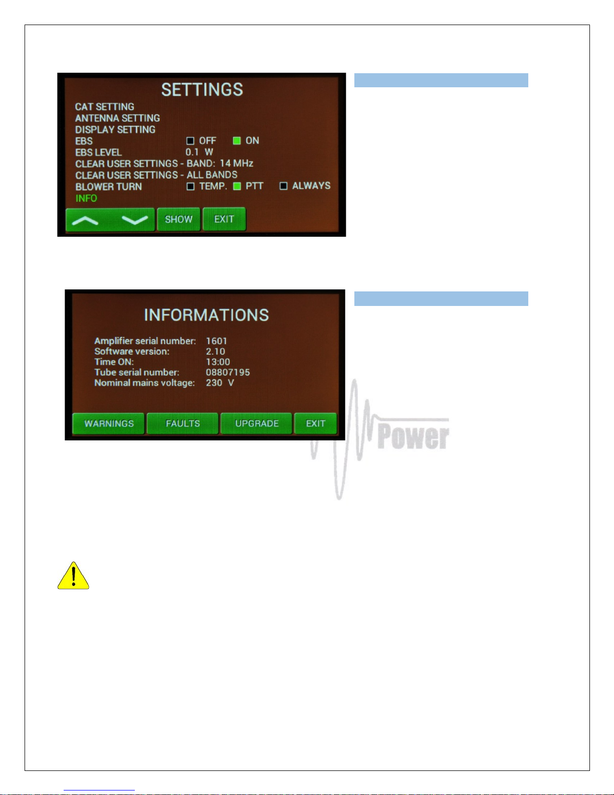
Last settings allows to see INFO. All of
previous information screen will be visible
plus one more for upgrade.
UPGRADE touch button can be used
ONLY in the case if EEPROM or firmware
files (or both) will be upgraded. In such a
case ask dealer or manufacturer for the
exact procedure.
5.3. Preparing for operation
In STBY the amplifier is in bypass-mode and your transceiver is directly connected to
the antenna. Maximum allowed power in bypass mode is 200 Watts! Passing RF power
is displayed if PA is in standby mode.
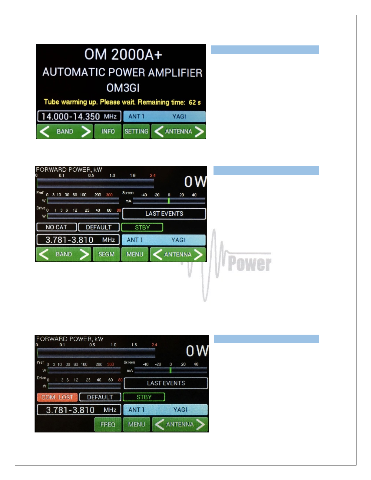
To turn PA ON press ON/OFF button on the front panel (black one) and hold it abt. 1 second. PA will
start tube heating. It will take 180 seconds. Turning PA ON is possible ONLY from the home screen! If
you have other display active, press EXIT more times to go back to the home screen.
Page 22
22
Time to go is visible on the display. Wait
until heating finish.
After heating finished PA will stay in STBY
mode and Main display will appear.
Depending on CAT settings you would have two possible situation illustrated. If NO CAT was saved,
above display will be visible. To set band and segment for transmitting, use BAND and SEGMENT
buttons. In this mode exact frequency will be read from RF input and PA will set up on it automatically.
Another display appears, if CAT was defined but TCVR is not connected with the PA (CAT cable). See
the following pictures.
FREQ button has two functions. It allows
to display working frequency or active
band segment.
Also in this case frequency will be read
directly from the TCVR in operation mode.
Page 23
23
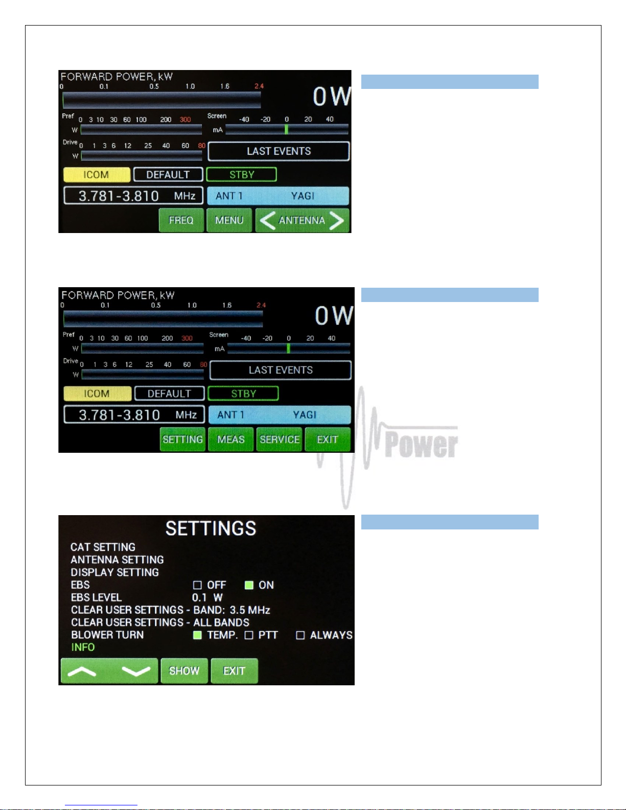
Use ANTENNA (left/right) to select one of
preprogramed antenna for that band.
Menu display allows to go deeper to the
SETTINGS mode, MEASuring mode or to
SERVICE mode.
Press SETTING button.
We are in the settings mode again, but
with little difference in INFO part.
Scroll to INFO and press SET.
Page 24
24
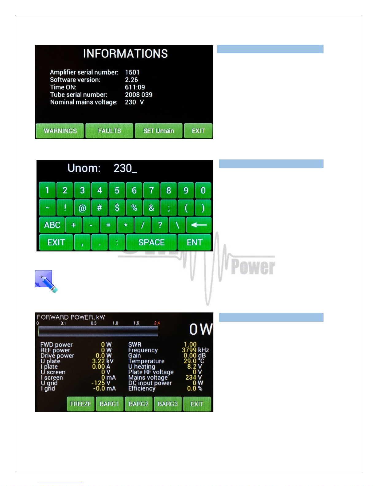
New button is visible – SET Umain. Press
it.
Type proper value of the primary voltage
and press ENT.
Press EXIT twice to go back to the Menu
display.
This means not programmable setting of the primary voltage. It is just information for the
processor, which protects the permitted limits ( up or down) for a given value of the primary
voltage (protection circuit).
MEAS pressing shows this screen.
Instantaneous values of the basic
parameters are displayed.
You can FREEZE the screen and
measure AGAIN.
Page 25
25
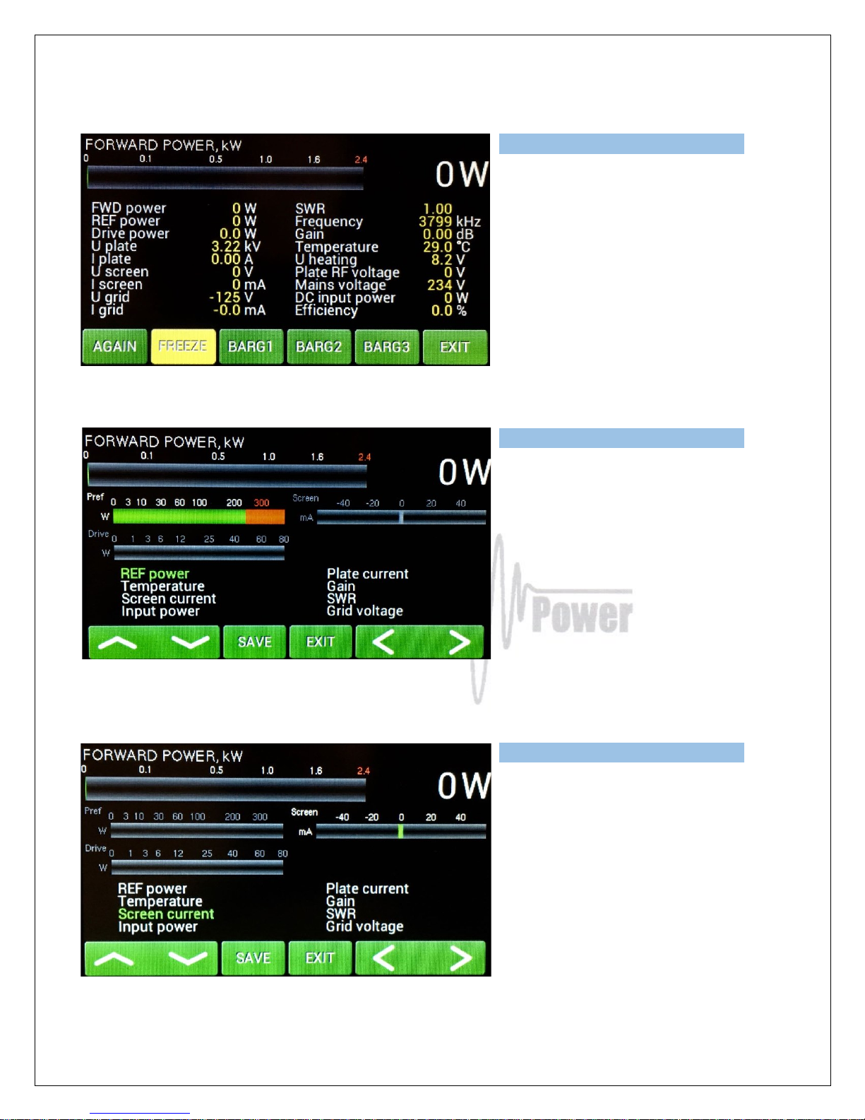
Three different bar graphs can be defined
using BARG1, BARG2 or BARG3 button.
Press BARG1.
Green graph may show one of the 8
parameters. Scroll to request parameter
and press SAVE. Screen jumps back.
Touch BARG2 in the next step, then the
same way BARG3.
Page 26
26
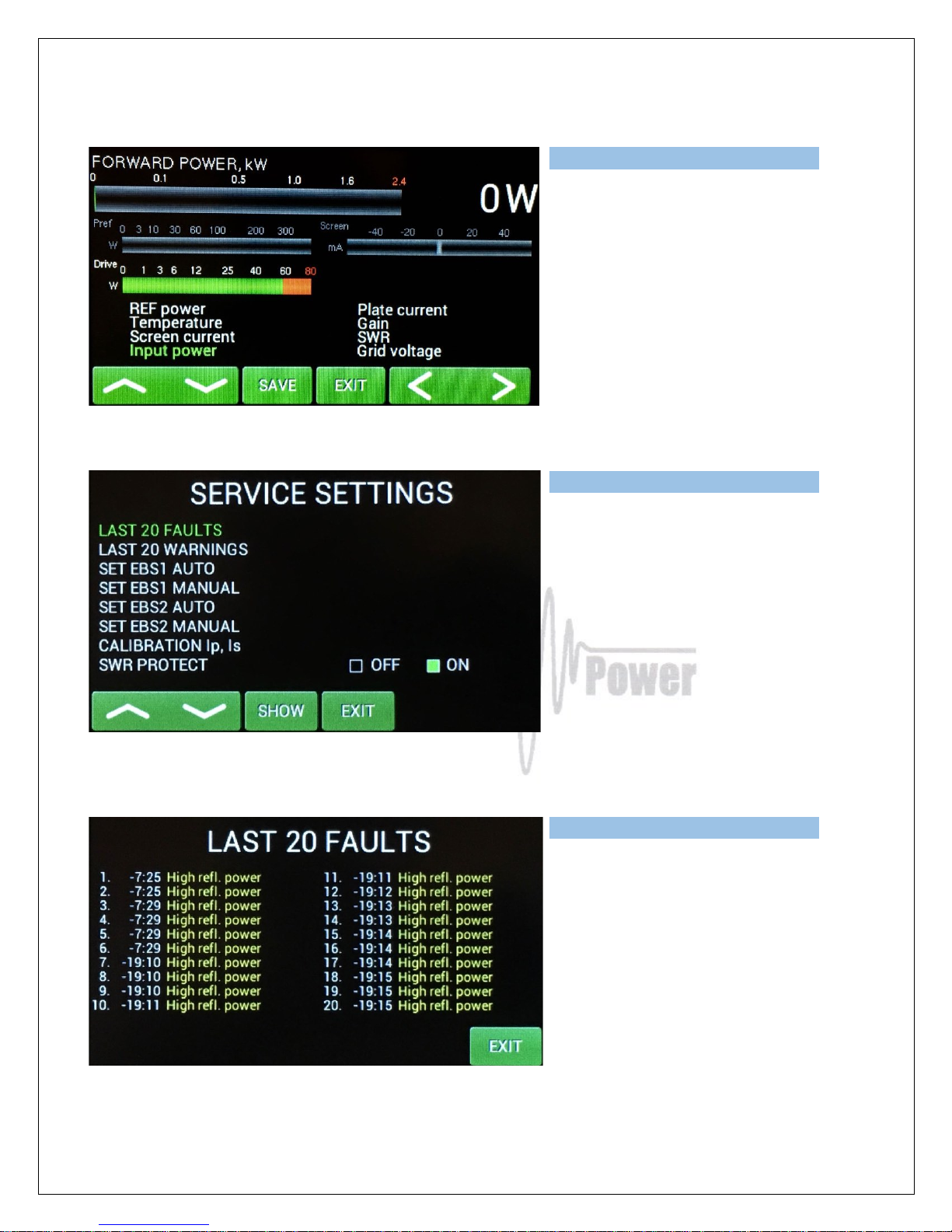
Press EXIT to go back to the Menu
display, then press SERVICE.
Now we are in the SERVICE settings
mode.
Scroll to selected line and press SHOW
or SET (depending on the line).
We selected last 20 WARNINGS to
show.
Press EXIT and go to the SET EBS1
AUTO and press SET.
Page 27
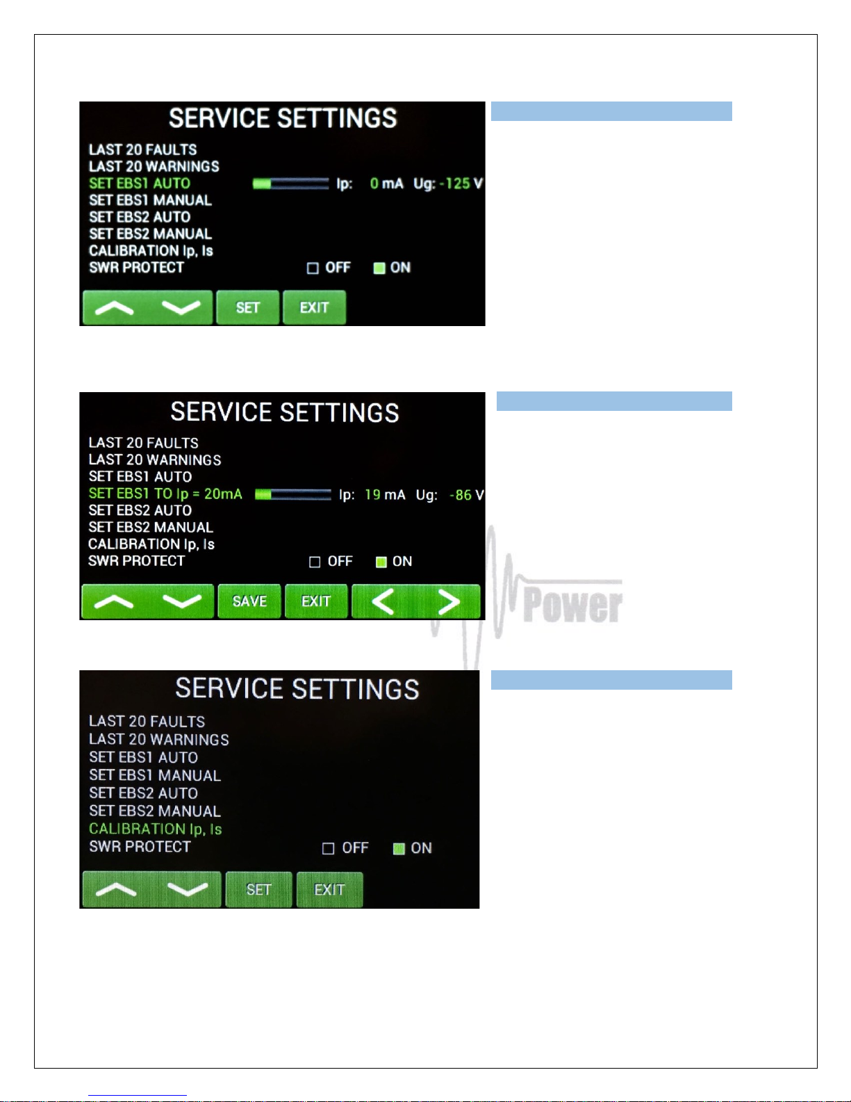
27
PA will automatically set 20mA of EBS.
You can try to do this manually, too.
Scroll to SET EBS1 MANUAL and press
SET.
Use left/right button to set 20mA or as
close as possible value and press SAVE.
Similar ways EBS2 can be
preprogrammed (250mA).
Scroll to CALIBRATION Ip, Is and press
SET. Calibration will be done
automatically.
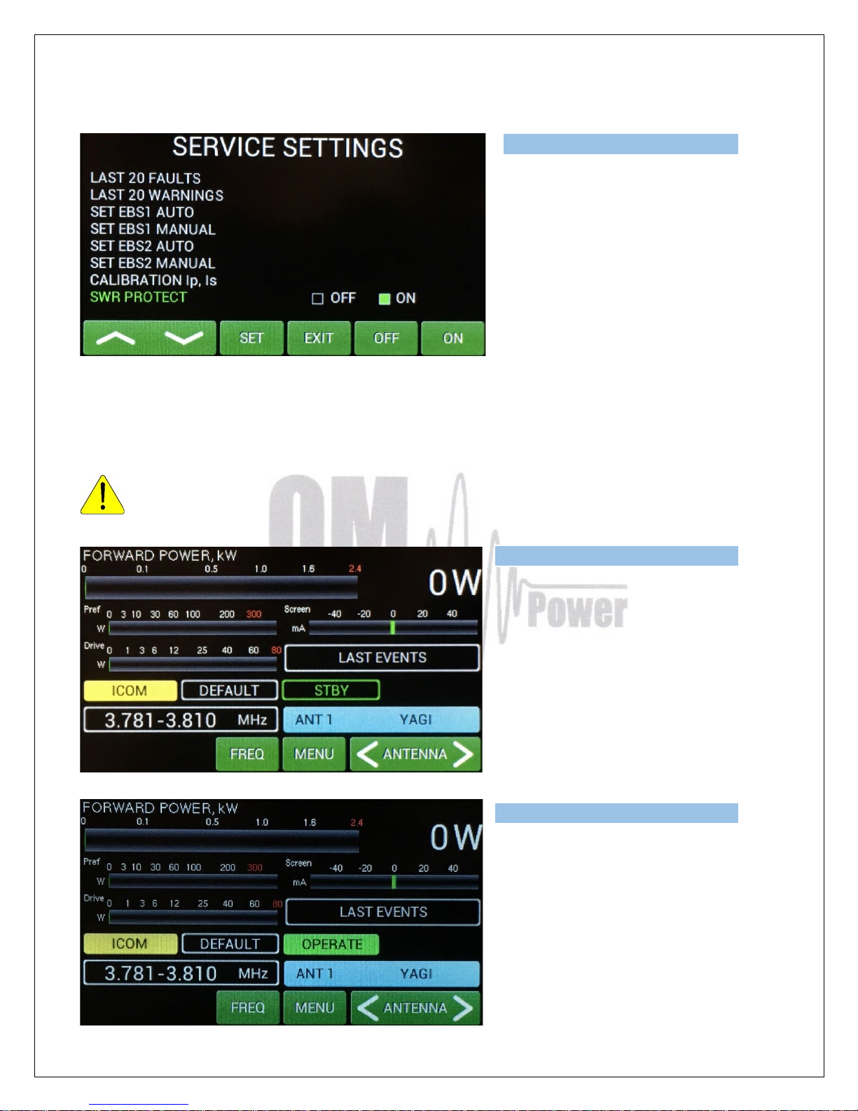
Go to the bottom line.
Page 28
28
This feature allows user to switch OFF the
SWR protection.
We recommend to set it ON (SWR
protection circuit will stay active, max.
allowed SWR is 3:1). If OFF is selected,
higher SWR is allowed, but reflected
power is measured. If it exceeds 350W,
transmit will be blocked.
Press EXIT.
5.4. Operation mode
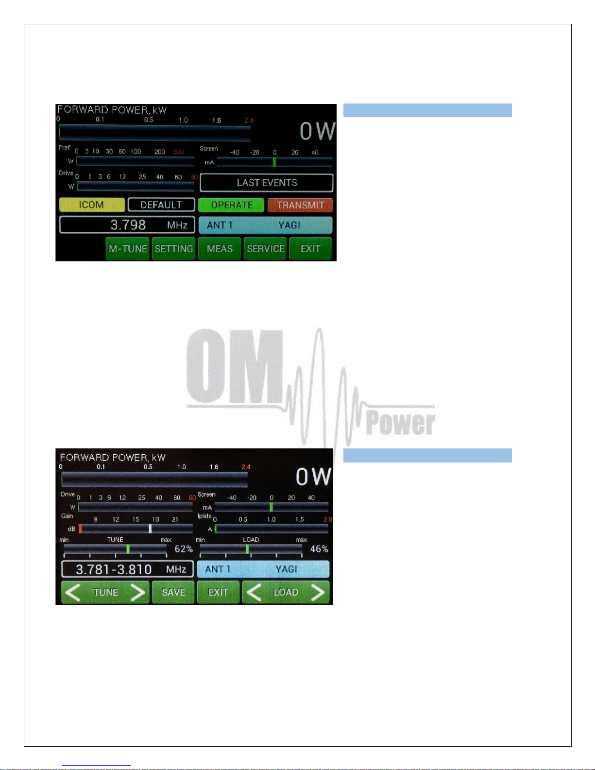
Before switching to operation mode, check all connections between PA and TCVR.
We are back in the Main display, bar
graphs were defined, antennas were
preprogrammed, CAT was set. We are
ready to go to the operation mode.
Press shortly black STBY/OPER button on
the front panel.
We are in the operation mode.
Press MENU.
Page 29
29
Now try to press PTT (foot switch for
example).
We are in the transmit mode (without RF).
We have new button here. M-TUNE.
M-TUNE means entry to the manual tuning mode. It allows fine tuning of PA, or in the case if automatic
tuning cannot set optimal adjustment of the PA. For proper adjustment we need to show Screen
current (at least). Prior start M-tune define one bar graph to the Screen current, or define all bar graph
as in the next picture.
Press M-TUNE. New screen is visible. Slides on the left and right side represent both variable
capacitors.
Adjustment process: Move TUNE left or right until maximum of FWD power reached. Then move
LOAD carefully so that Ig2 Screen current will be not higher than 20mA. Optimum means maximum
FWD power and Screen current between 0– 20mA for the full power output. Repeat more times.
After adjustment press SAVE for writing
values to the memory and press EXIT.
Repeat adjustment process for other
segments / bands.
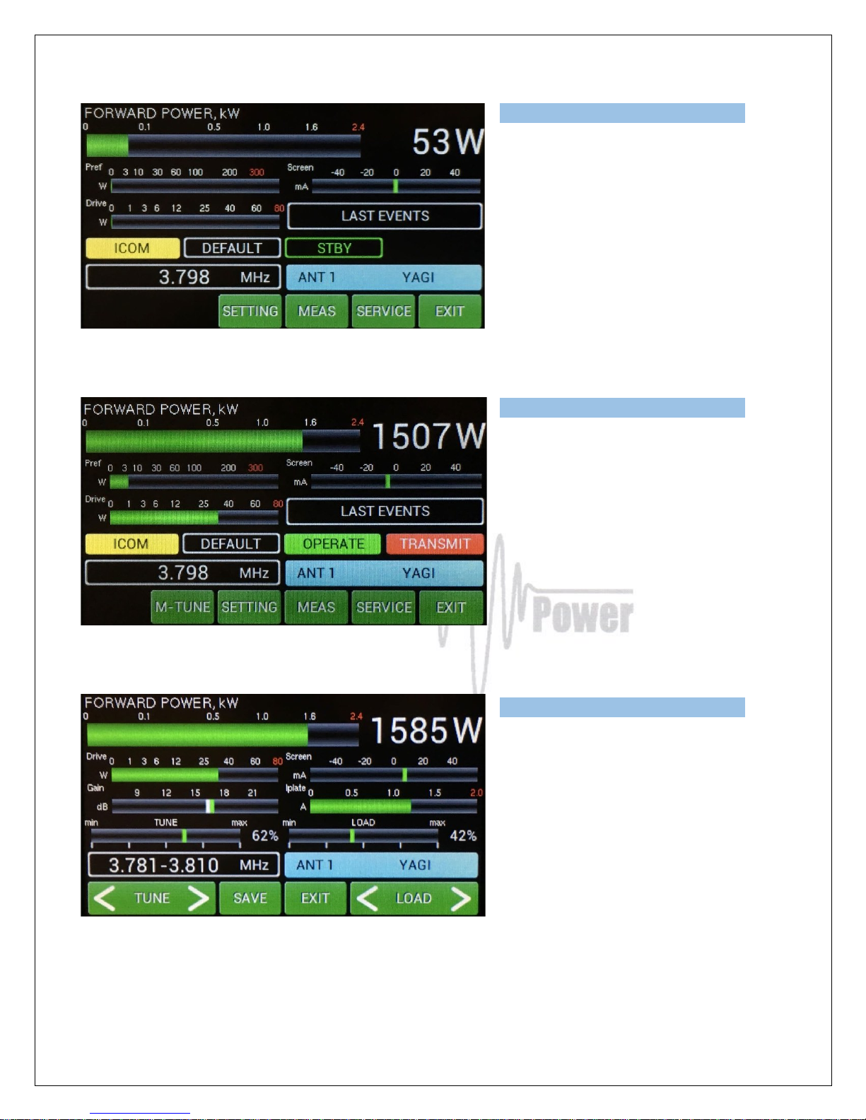
Now one example from real situation. First we will check driving power from the transceiver. Stay in
STBY mode, press PTT and apply RF power.
Page 30
30
Measured driving power is 53 Watts.
Now switch to OPER, press PTT and apply
RF from TCVR. See the following picture.
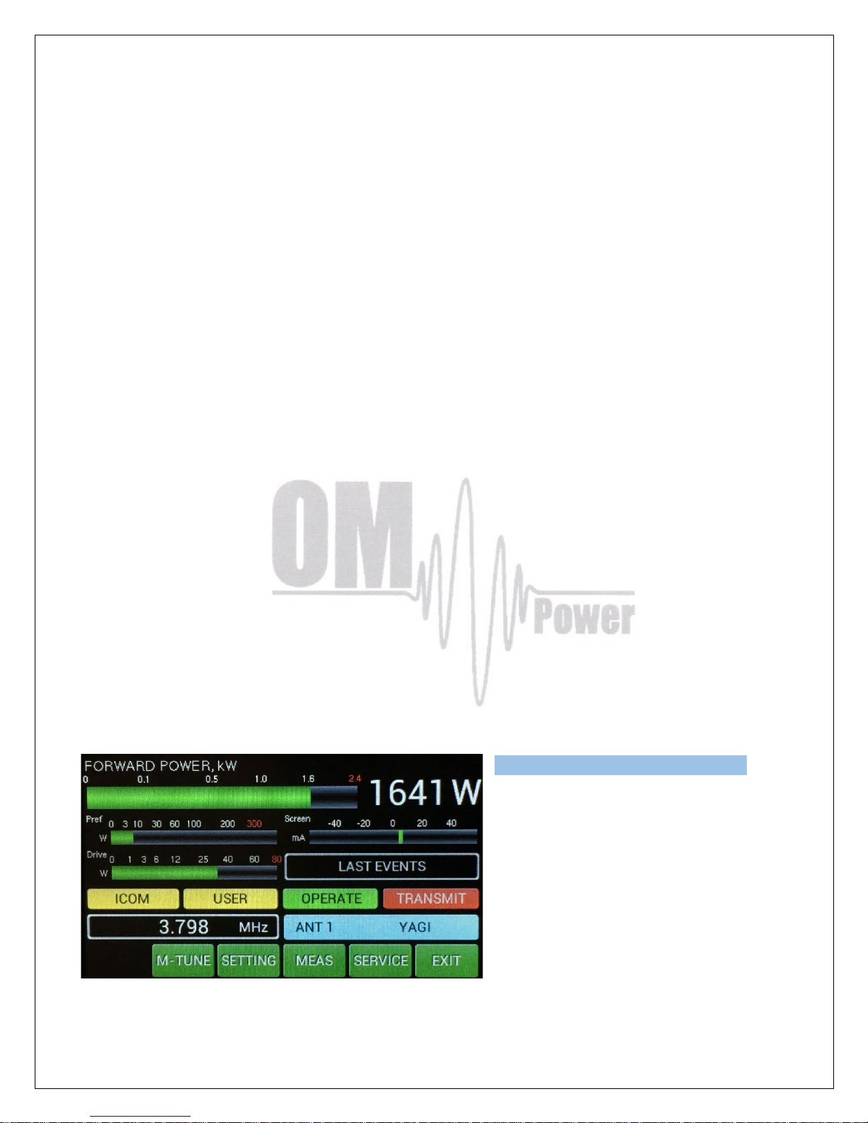
Output power is 1507W, reflected power
reached abt. 4W and screen current is abt.
-8 mA.
If your antenna has different impedance
than real 50 Ohms then is necessary to
start the M-TUNE procedure to optimize
PA adjustment (press MENU, M-TUNE)
and make the manual adjustment.
This is the result after manual adjustment
process. Output power increased to 1585
W. Screen current is now abt. +10 mA.
These parameters were SAVED.
Notice: OM2000A+ is factory adjusted to maximum output power of 1500W to the real load 50 Ohms.
Unique Tuning table with TUNE and LOAD values for every band is supplied with each PA.
Page 31
31
When the antenna impedance has greater tolerance, it may be the case that the PA can not deliver the
full power 1500W, or some of protection circuits will be automatically activated. In such a case we
recommend to do manual tuning.
The best indication of proper PA tuning is the Screen Current. In the properly tuned PA to be within 0
to + 30mA (at full output power).
Tunung procedure:
• Press M-TUNE button. IF CAT is active, TCVR will automatically tune itself to the middle
frequency of the segment. If NO CAT, you must tune TCVR manually to the segment center
frequency. Set CW or RTTY mode in the TCVR.
• Press PTT and increase gradually the input power of the PA to reach abt. 70% of its maximum
output power.
• With TUNE buttons adjust maximum FORWARD POWER while monitoring the Screen current.
• When Screen current exceeds +30mA, use right LOAD button to decrease current to abt. 0 mA.
• Increase the input power until you reach the maximum output power. Again watch the Screen
current. If exceeds +30mA, decrease it using right LOAD button.
• Repeat TUNE buttons using to reach maximum FORWARD POWER and check Screen current.
• If Screen current is lower than 0 mA (negative value), change it with pressing right LOAD button
until 0 mA is set and check again the maximum output power.
• If you reached maximum output power and Screen current is inside 0 to +20mA, press SAVE
button.
Notice 1: If tuning process takes more than 1 minute, make a short brake to prevent temperature
overloading of the PA.
Notice 2: If you will use PA with the output power lower than maximum, Screen current can take
negative values. There is no necessary to readjust the PA, it is working still in the linear mode.
We
We can see new small yellow window.
USER means that we used manual tuning
feature to optimize the PA adjustment.
If you want to go back to the default factory
settings, use CLEAR USER SETTINGS in
the MENU settings (page 15) – for one
band or all bands.
Page 32
32
If the amplifier demonstrate any malfunctions during tuning or it does not behave in accordance
witch the description, interrupt the tuning procedure immediately and check the amplifier! Be
sure not to do any mistakes in choosing antennas, bands or segments! Be sure that VSWR is
not higher than 3:1 and input power is LOW!
After excluding possible human mistakes you will be able to work for long time with this amplifier!
6. MAINTENANCE
6.1. Indication of Fault Conditions
If a fault condition appears during the operation of the amplifier, the safety circuits of OM2000A+ will
react. There are several warning or fault messages possible to appear on the display, when some of
the protection will be activated. The OM2000A+ power amplifier can report one of the following
messages:
Power Out is too high
Refl. power too high
Power In is too high
Low output power (tune)
Plate current too high
Grid current is high
Screen current error
Heating voltage error
HARD FAULT
Plate voltage error
Grid voltage is low
Screen voltage error
SWR is too high
Amplifier is too hot
Most of safety circuits are preset for two levels of exceedances. First level is a warning level. In
such a case a warning message appears on the display, but power amplifier will stay in
normal operation. See the table below for warning and fault conditions.
When a fault condition appears during the tuning or operation of the amplifier, the safety
circuits will block transmitting. The amplifier stays in OPER mode. After approx. 1 sec the
control circuits will automatically switch the amplifier back to the transmitting mode. If problem
persists, safety circuit will react again.
If the fault will repeat 3 times during 10 seconds, the safety circuits will turn the amplifier
to STBY mode. To cancel fault status, press STBY/OPER shortly. Power amplifier will
stay in STBY mode.
Page 33
33
ll the warning and fault messages are stored in the memory. You can display particularly warning
messages and particularly error messages. They are stored one by one to the memory. You can see
them on the display. If memory is full, every new message will delete oldest one and move rest of them
one position back. It means that every time last 20 messages are visible on the display.
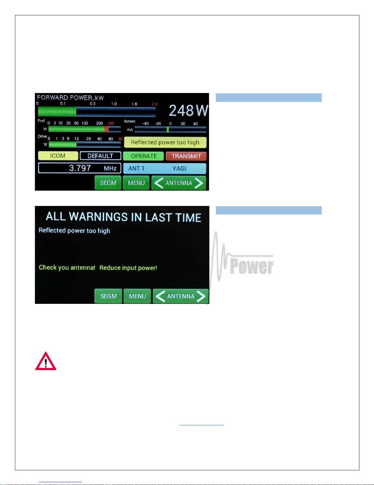
This an example from previous attempt,
when antenna was disconnected from the
PA during transmitting.
Reflected power was higher than 250W,
warning message “Reflected power too
high” appeared.
If you touch the yellow box, warning details
will be visible.
In the case of some hardware failure or if your power amplifier is not working properly, please contact
the manufacturer or your dealer.
Never try to change or move any part inside the amplifier except of tube or fuses.
Substitution of parts may void intrinsic safety!
Dealer in the USA: Array Solutions
2611 North Belt Line Road
Suite # 109
Sunnyvale, TX 75182
Tel: (214)954-7140
Email: sales@arraysolutions.com
Page 34
34
6.2. Fuse Replacement
The user is allowed to change mains 20A fuses (6.3 x 32mm), accessible from the rear panel, only. In
the case of fuse (fuses) interruption inside the power amplifier, exchange can be carried out only by
professionally qualified person! Internal fuses are located mainly on the SWITCH-on board (next to
the HV transformer).
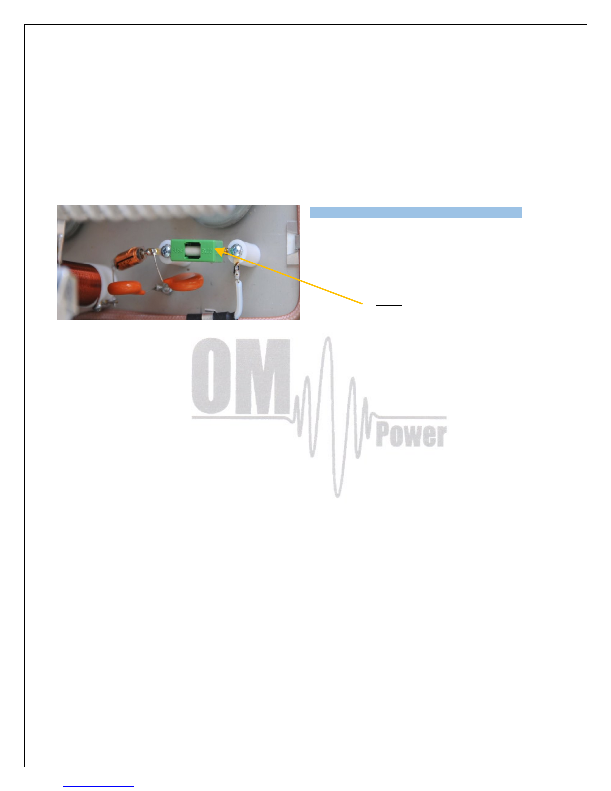
One special fuse is used in the model OM2000A+.
In the case of an accidental discharges in the tube
this fuse saves HV supply circuits.
Fuse
6.3. Tube Replacement
In the case of vacuum tube damaging, contact the manufacturer or your dealer for ordering new one.
You will get instructuions how to change it. Exchange can be carried out only by professionally
qualified person! After tube replacing automatic BIAS adjustment must be done.
6.4. Cleaning
To prevent damage to amplifier surface and plastic components do not use aggressive chemicals for
cleaning. Do not open the amplifier for cleaning. Outer surface may be safely accomplished by using
piece of soft cotton cloth moistured with clean water or window cleaner.
7. APPENDIX
7.1. Primary AC voltage selection
Primary section of the HV transformer is switchable for three values of AC voltage (230, 240, 250V).
Factory settings is 240VAC. Before first starting of the PA we recommend to check the correct value
according to the AC voltage in your network. Change the settings, if necessary.
Page 35
35
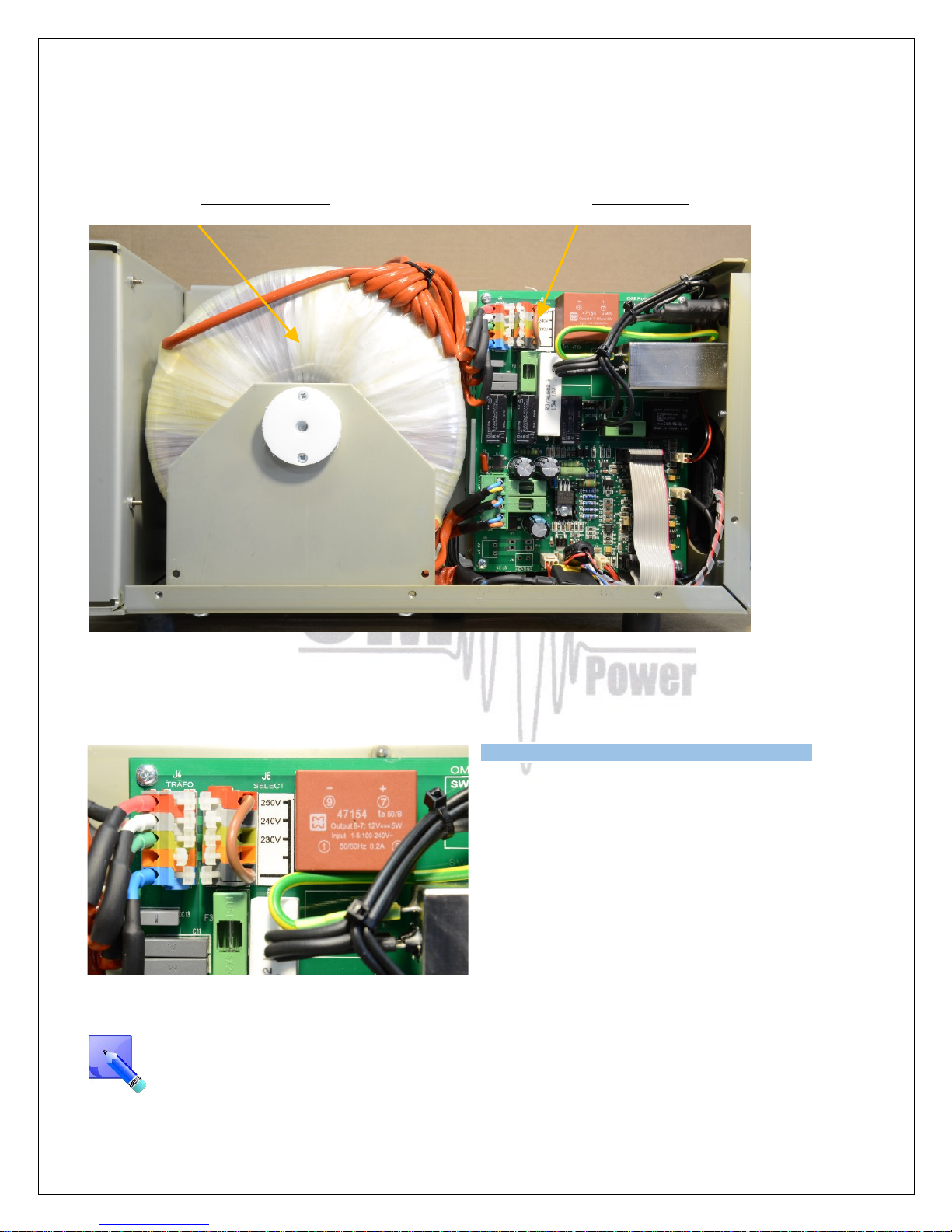
Side view on the opened OM2000A+
HV Transformer AC Selector
Remove the upper lid first. On the right side of the PA, next to the HV transformer there are two PCBs
mounted. On the left upper side of the front (Switch-ON) board connector J6 is located.
Use flat screwdriver or finger and press carefully
the white stick to release contact and move upper
end of the white jumper to the proper position, if
necessary.
Jumper must be connected between bottom contact
and one of remaining contacts. AC voltage is
marked next to every contact.
AC selector range can be changed in the production according to the specific conditions in
individual countries. Default settings is 220V – 240V / 50 Hz for EU market and 230V – 250V /
60Hz for US market. If you need different settings in the range of 200 – 260V, this should be
specified in the order!
Page 36
36
7.2. Removing HV Transformer
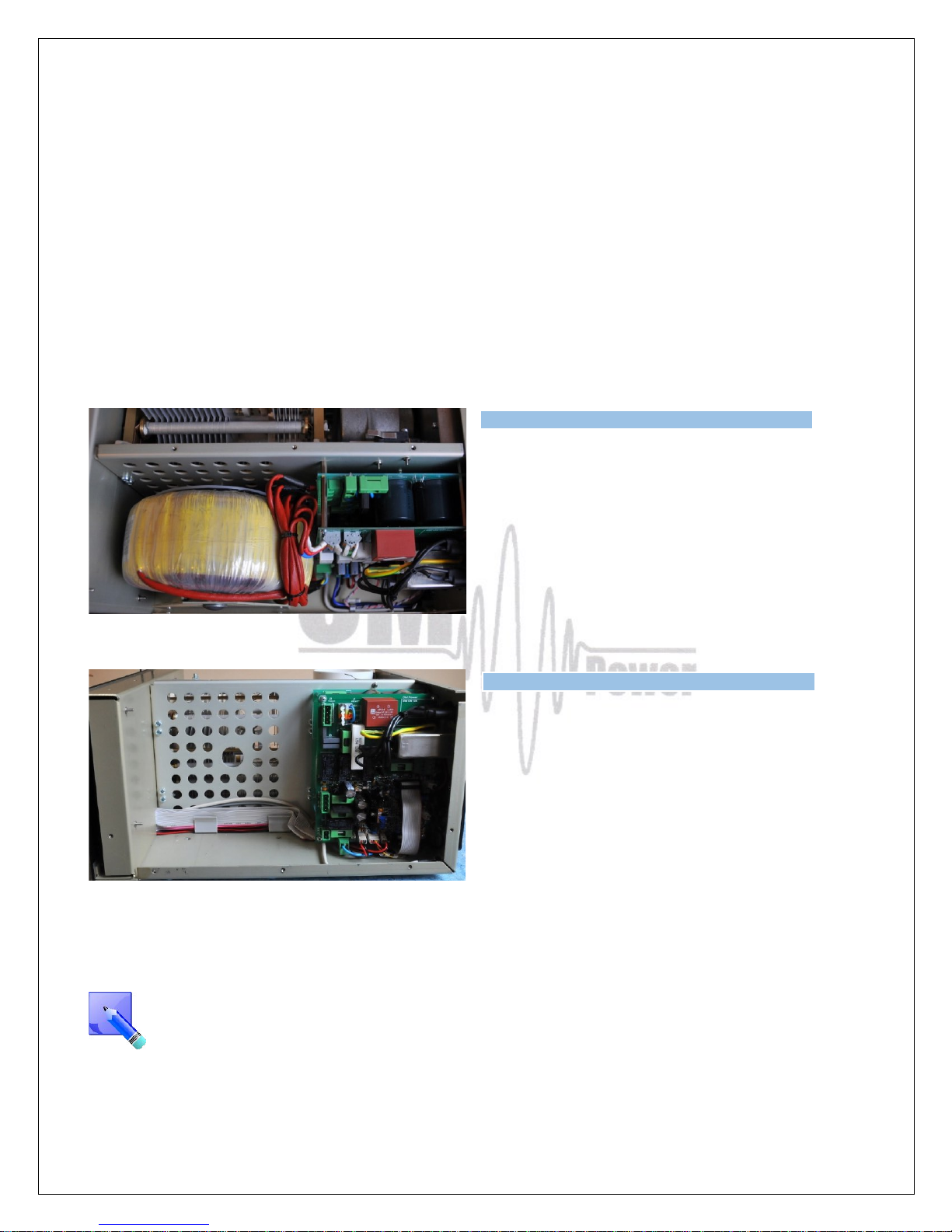
For simpler and easier transport of the PA, HV transformer can be removed and taken separately. This
distributes the weight of the PA (24 kg) about half and half. Follow next steps to do it.
1. Remove upper lid from the PA (use Phillips screwdriver bit PH1 !) .
2. Turn the PA on the left side (transformer is up).
3. Disconnect 3 connectors from the front board and 1 connector from the rear board.
4. Release 4 screws from the bottom side of the PA. Use Philips screwdriver bit P2. During the
release of the last 2 screws hold the transformer by hand. Do not worry about its weight, it will
move down just 1 cm and remains on the central rung of the PA.
5. Use both hands to take transformer away from the chassis.
Watc
h the released terminals, when moving the
transformer!
Do not damage transformer insulation during
removing and transportation.
Weight of the PA was distributed (transformer
has 12 kg, rest of the PA has cca 12 kg, too).
When refitting the transformer, watch to the correct location of individual sections and wires.
Manufacturer reserves the right to make future changes in the way of connecting the
transformer to the board. Allways mark the position of the terminals before disconnecting the
transformer.
Page 37
37
7.3. Controlling the OM2000A+ with Flex Radios Series 6xxx
There are two possible methods to connect Flex Radio series 6xxx belong to OM2000A+:
• Using SmartSDR CAT program
• Using USB connector at Flex 6xxx
Flex Radio 6xxx series connection using SmartSDR CAT
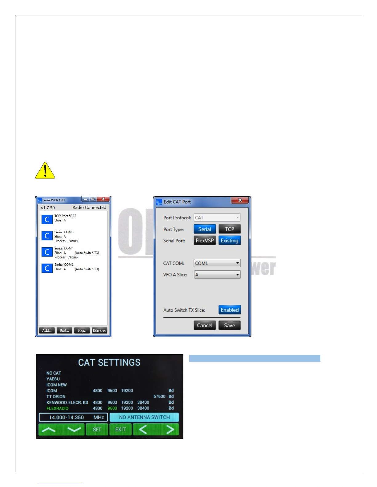
Choose the control port in the SmartSDR CAT window that you will use to control the power amplifier. It
must be an existing serial port – a hardware COM port in your PC or an USB to serial port adapter.
Connect the chosen COM port and the transceiver port ( TCVR DB9 )to the OM Power amplifier with a
null modem serial cable (both ends of the cable with a female DB-9 connector and pins 2 and 3 are
crossed).
You must use it for the TX slice that is associated to the connecting port otherwise the amplifier
will not to be set on the proper frequency.
In the CAT SETTINGS menu select FLEXRADIO,
baud rate 9600 and press SET.
Page 38
38
Flex Radio 6xxx series connection using USB output
Connect USB from Flexradio directly to TCVR port on OM2000A+ using USB – serial port
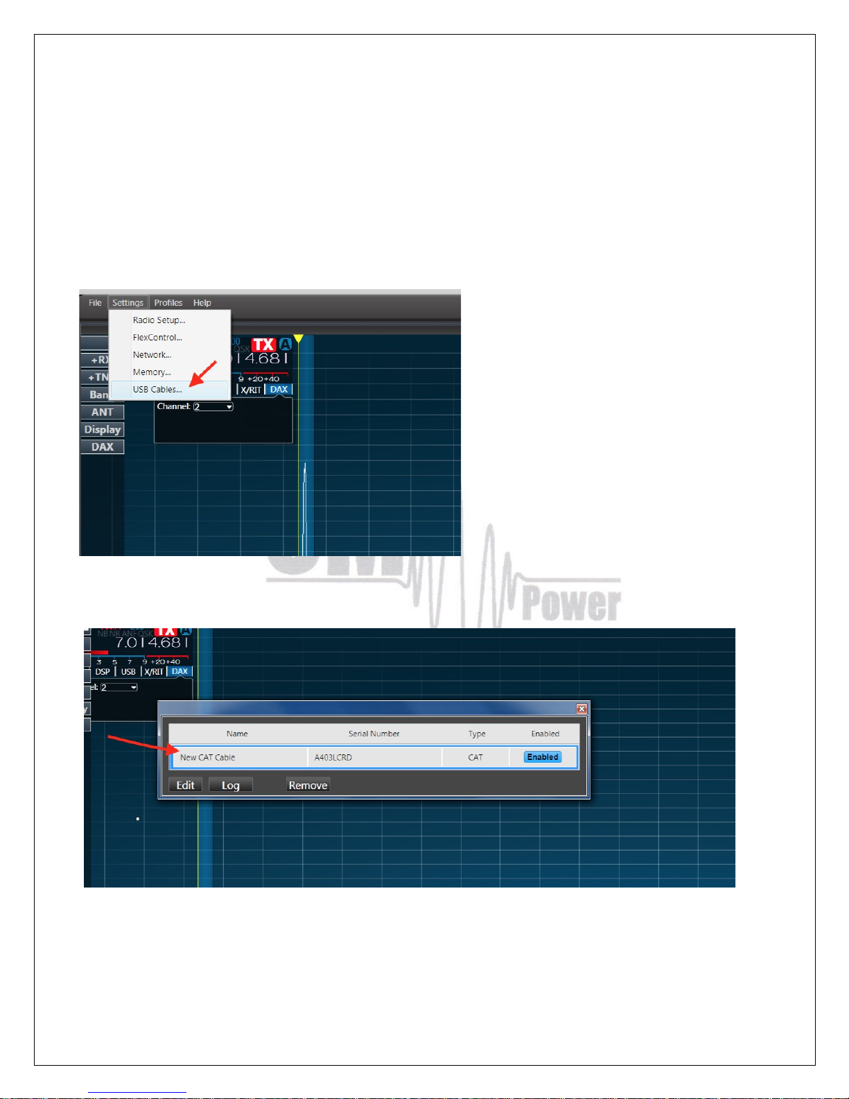
adapter and a null modem serial cable (both ends of the cable with a female DB-9 connectors (pins 2
and 3 are crossed).
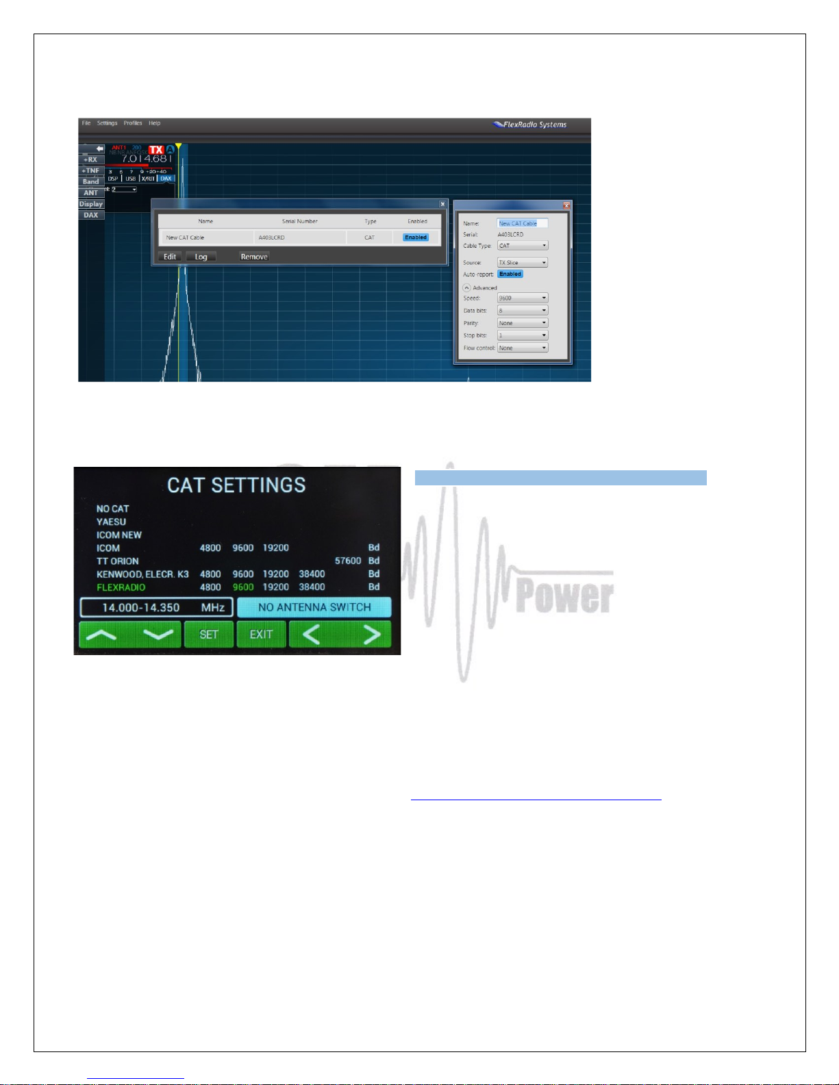
Activate the smartSDR and choose Settings / USB Cables
(USB adapter to serial connect to USB port of Flexradio). Line with connected USB adapter will
appear.
Make double click on the line (with connected USB adapter after that appears possibility) to open
configuration window for COM port .
Set all parameters in the table according the picture below. In both windows ENABLED must be
selected.
Page 39
39
Close both windows. (USB adapter connect trough null modem cable to TCVR port on OM2000A+).
In the CAT SETTINGS menu select FLEXRADIO,
baud rate 9600 and press SET.
7.4. OM2000A+ Remote Control
The OM Power team developed special software which allows control the PA OM2000A+ remotely.
Download it from the official OM Power website http://www.om-power.com/downloads. First unzip the
downloaded file, then open software.
The software allows user:
• Switch PA ON and OFF
• Switch between STBY and OPERATE
• Switch between preprogrammed antennas
• Read and reset last 20 warnings and fault statuses
• Fine tuning of the PA
Page 40
40
• To check almost all operation parameters of the PA
• To select different screens
• Antenna retuning if parameters changed
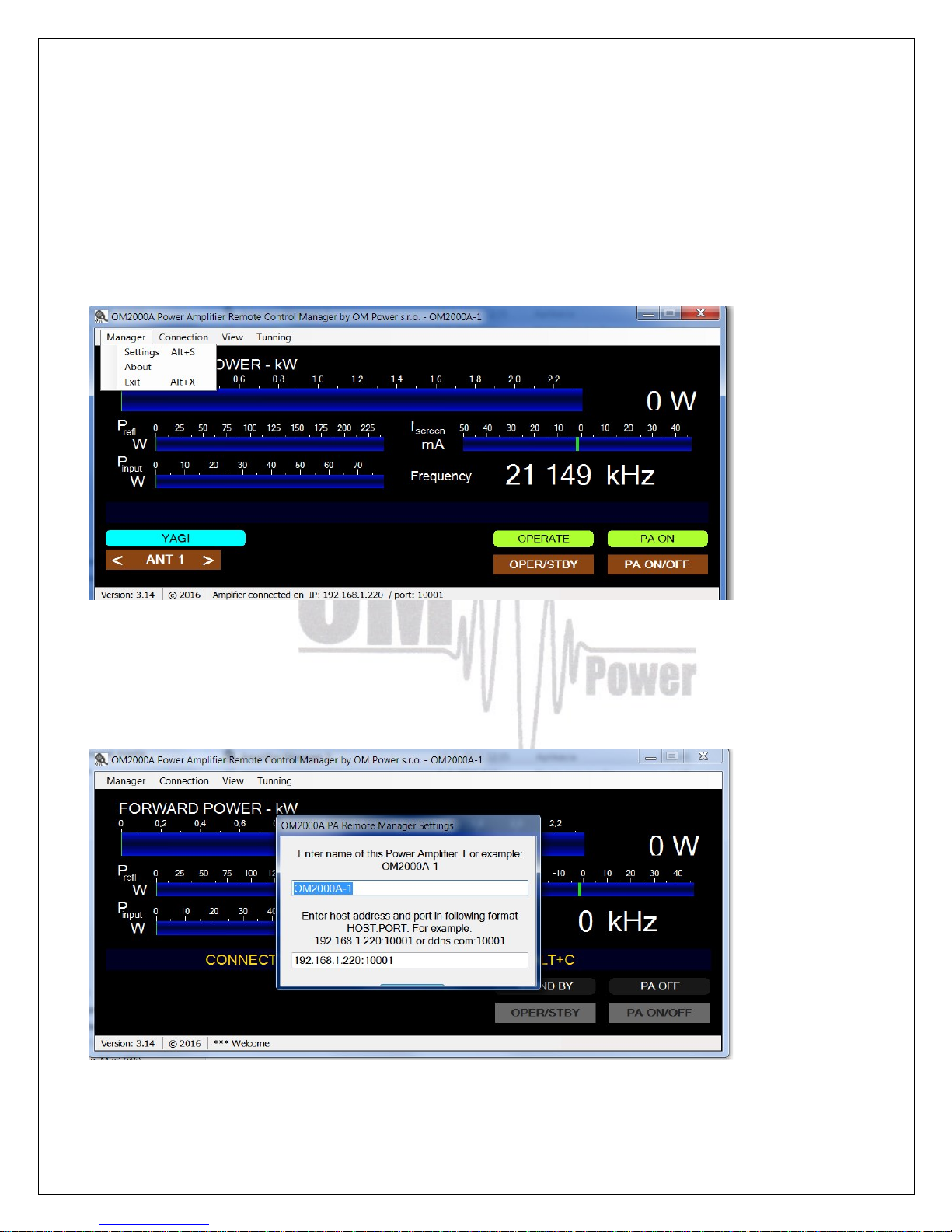
Have a look on the next pictures and follow instructions to setup remote control properly.
Connection setting.
Set up TCP/IP address and port
Page 41
41
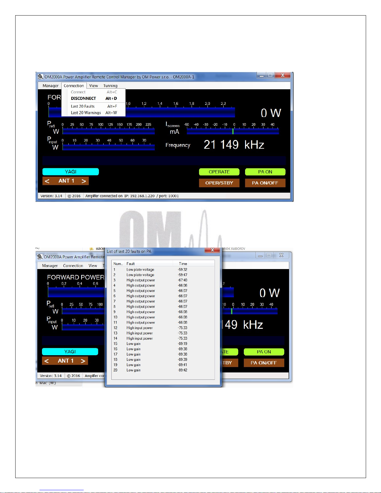
Connect / disconnect to OM2000A+
View last 20 PA faults
Page 42
42
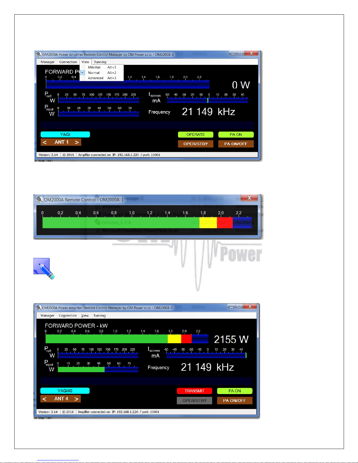
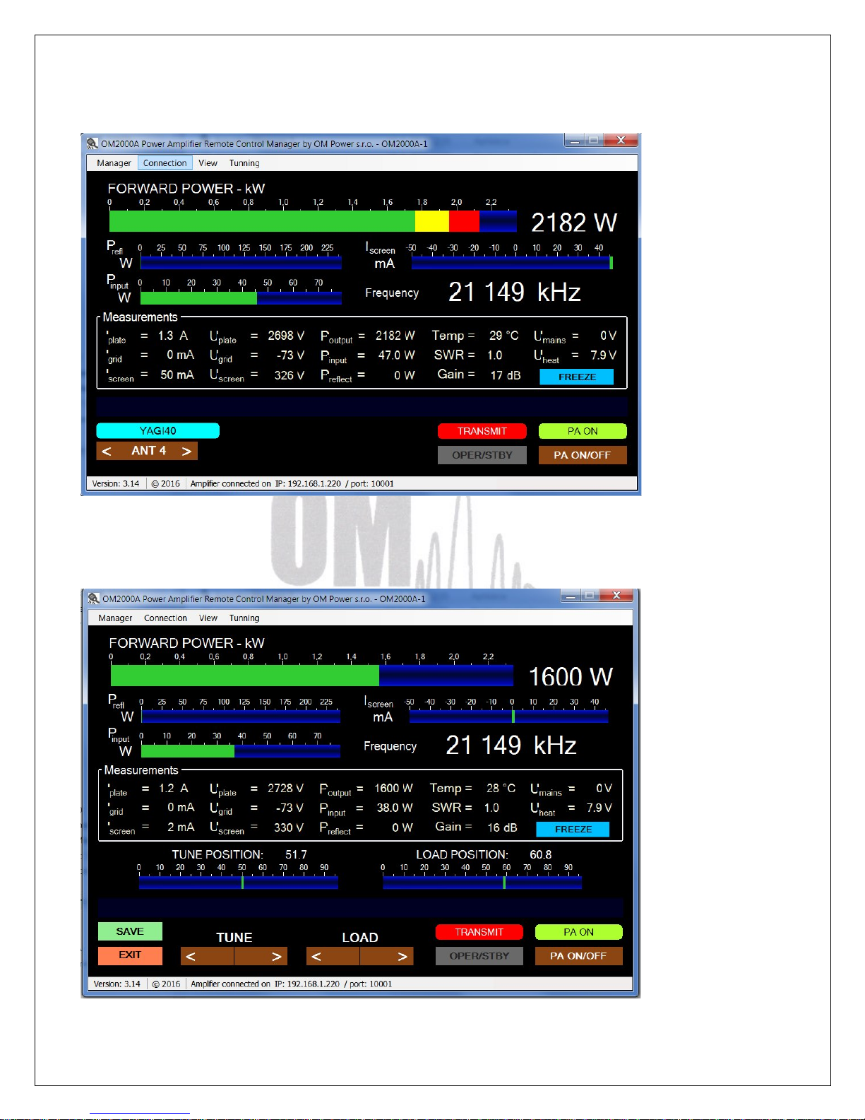
There are three possible screen selectable
Minimal view
To go back from Minimal view click with right mouse button and close it. Normal view will
appear back.
Normal view
Page 43
43
Advanced view
Fine tune screen. It is possible to retune the PA remotely (if antenna parameters changed, for
example), too. Proceed the same way than with local control (page 28).
Page 44
44
7.5. Remote Control using own public IP address
7.5.1 Changing OM2000A+ connection settings
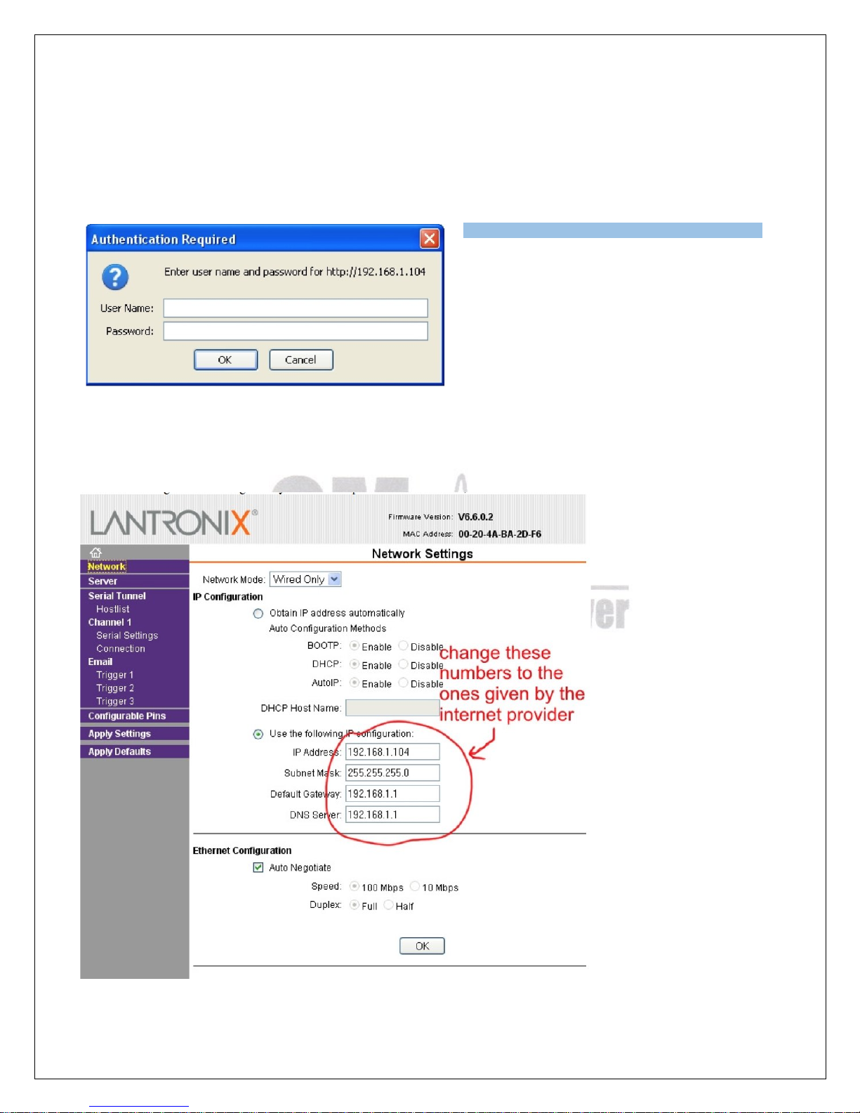
Connect LAN connector on OM2000A+ to PC with ethernet cable.
Open up a WEB browser and enter the OM2000A+ current IP address (default is 192.168.1.211).
An authentication window will show up. Leave
the fields empty and click OK.
Open Network menu and change the IP address, Subnet mask, Default Gateway and DNS Server
settings to the ones given by the internet provider. When done, click OK.
Page 45
45
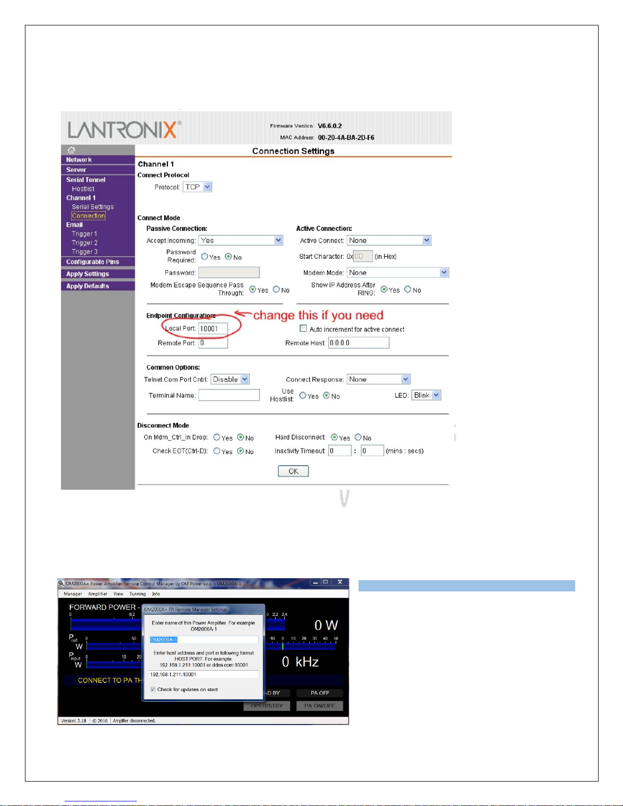
You can change the OM2000A+ Port number too, if you need / want in the Connection menu. When
done, click OK.
When done, click Apply Settings in menu.
7.5.2 Setting up in the Remote software
In the Remote Control software open
Settings and enter the IP Address and Port
number that you set in point 7.5.1.
Click enter, when done. Now you are
ready to work with OM2000A+ over the
internet.
Page 46
46
7.5.3 Remote Control without own IP Address, behind a router
If you need to change the OM2000A+ connection setings for some reason, use point 7.5.1 writen
above.
Change router´s settings
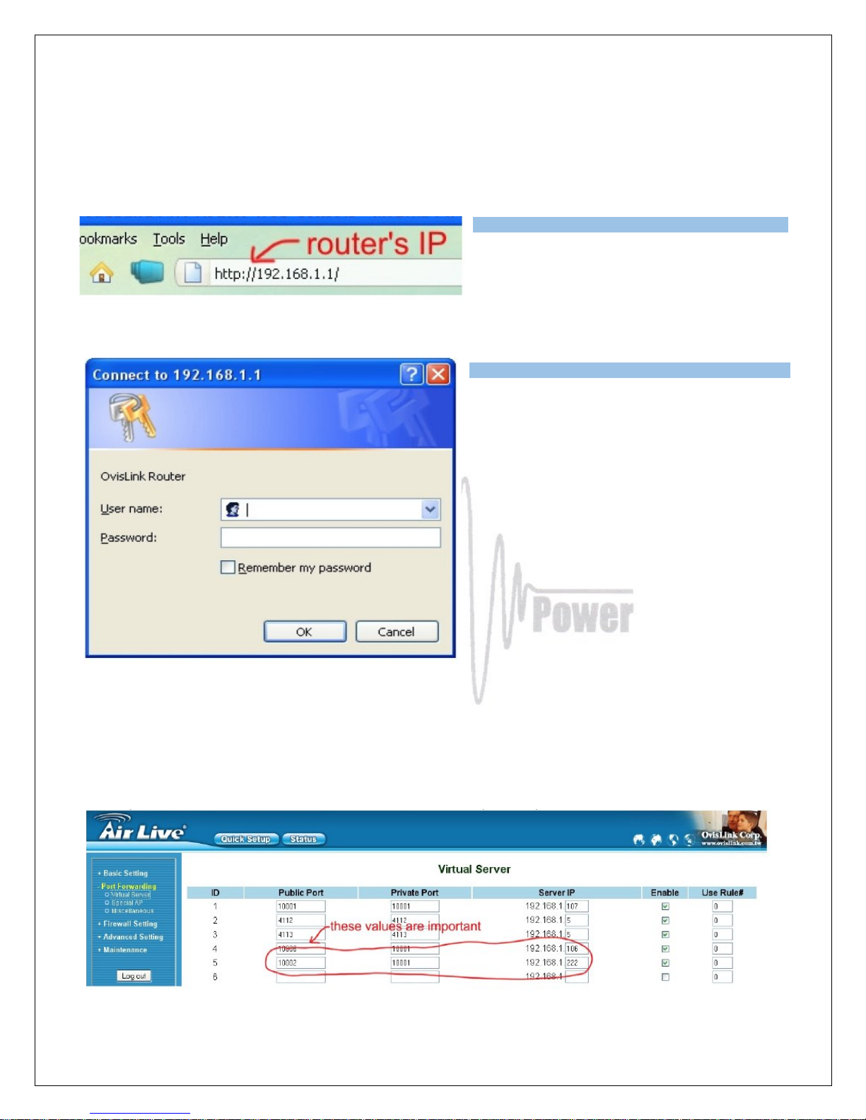
Open up a WEB browser and enter the
routers´s internal IP Address ( usually
192.168.1.1)
An authentication window WILL APPEAR.
You need to enter the routers login and
password. Usualy a router´s default login is
“admin” or “administrator” and default
password “admin” or an empty field.
Open Firewall Settings (depends on router software, can be called Forwarding, Port Forwarding, or something
similar). As Server IP enter the OM2000A+ IP Address, 192.168.1.211 if you haven't changed it, or the one you
changed to in point 7.5.1. Private port should be 10001 in default, or the one you changed to in point 7.5.1. Some
routers THEY don't have a separate Public Port settings. If you got, enter a free port number (usually the default
10001 is free and usable). Check the Enable box too. When done, click OK (or Save).
Page 47
47
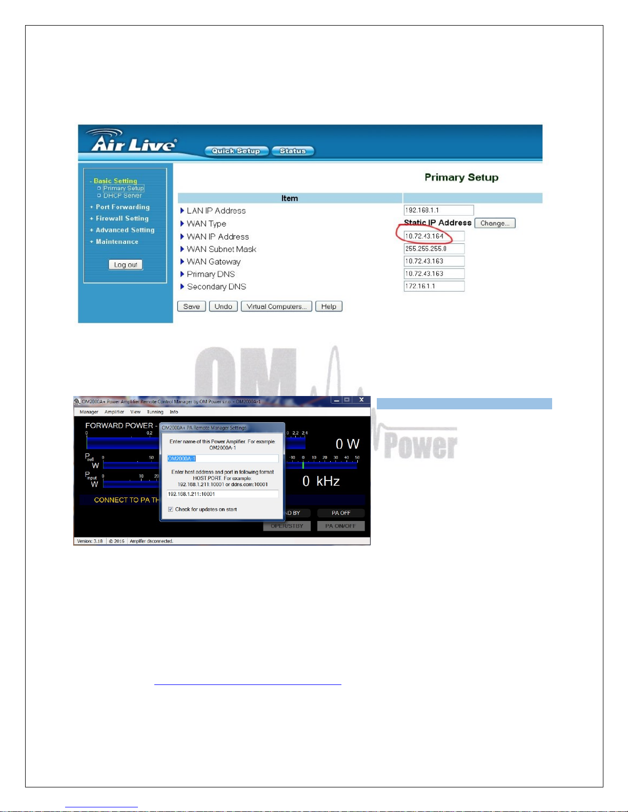
Open Basic Setup (or WAN Settings or similar, depending on router) and note the WAN IP Address
value.
In Remote Control software, open
Settings. Enter the IP Address and
Port number you set up in previous
point in your router. IP Address is
the WAN IP Address in basic setup
page and Port number is the Port
(or Public Port if separate) in
forwarding page. When done, click
enter.
Now you are ready to work with OM2000A+ over the internet.
7.6. OM2000A+ firmware upgrade
Download firmware upgade software and latest firmware file for OM2000A+ from the official OM
Power website http://www.om-power.com/downloads. Store it to OM2000A folder in your PC.
Use serial null modem cable and connect TCVR port on OM2000A+ rear panel with COM port
on the PC.
Page 48
48
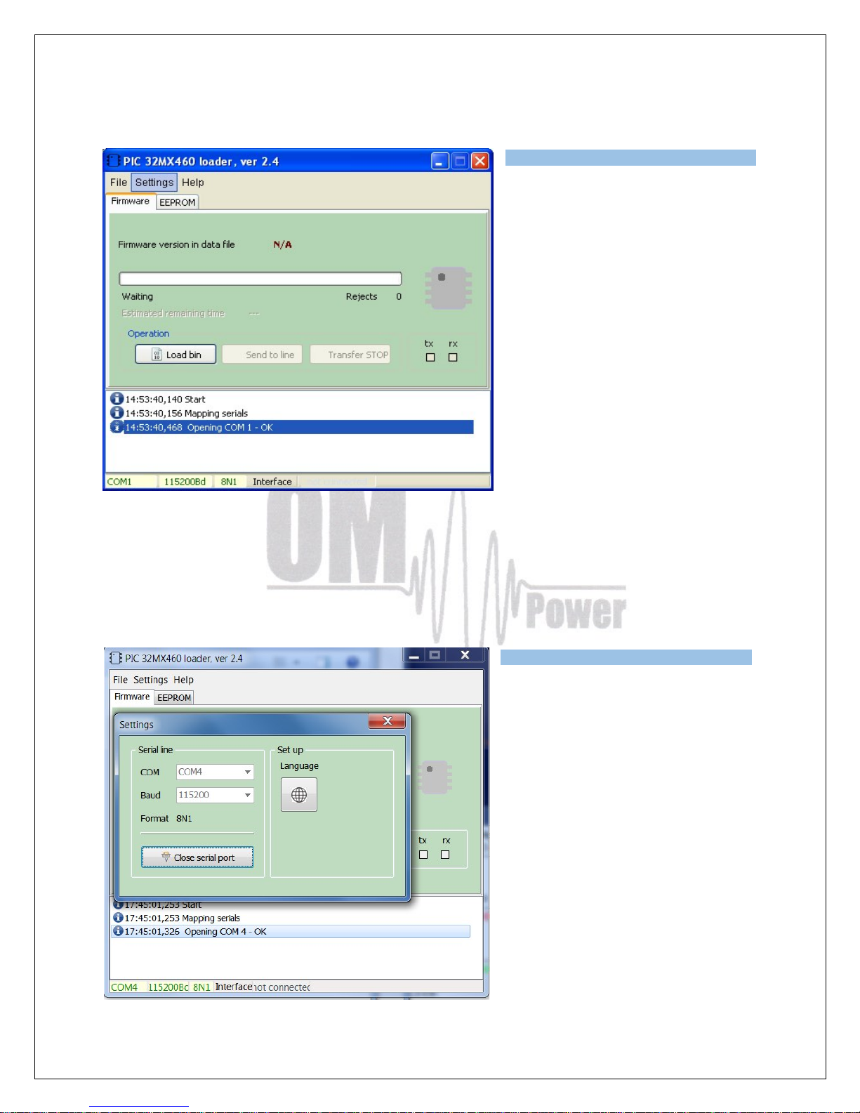
Open folder OM2000A , find MX460L.exe file and run it.
Select SETTINGS and choose COM port you want to use. Baud rate should be 115200. Close
the window.
Page 49
49
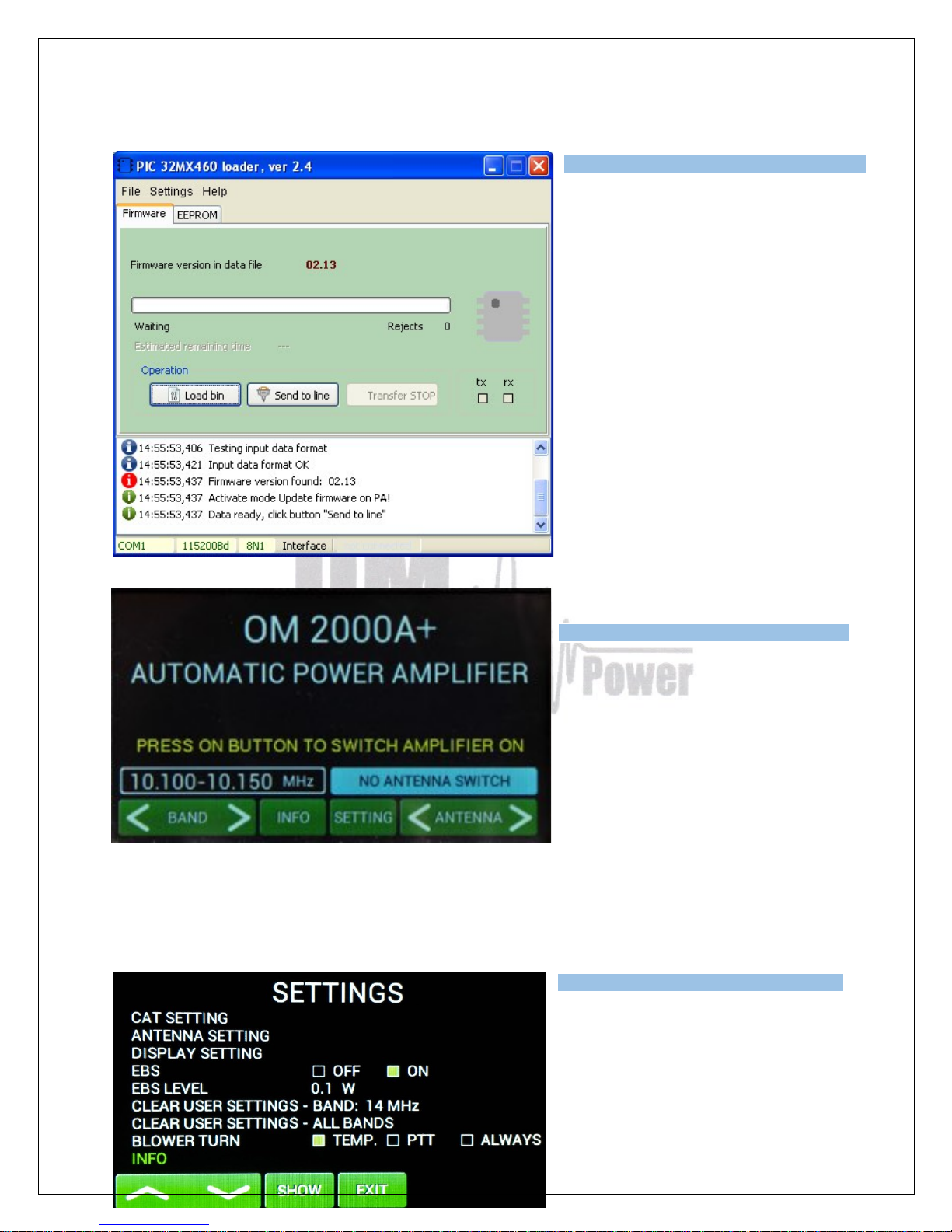
Select the Firmware tab and click
on LOAD BIN
Choose OM2000A+ Vxxx.bin file in
the OM2000A folder.
Switch ON power amplifier using
mains switch.
Press SETTINGS.
Choose INFO and press SHOW.
Page 50
50
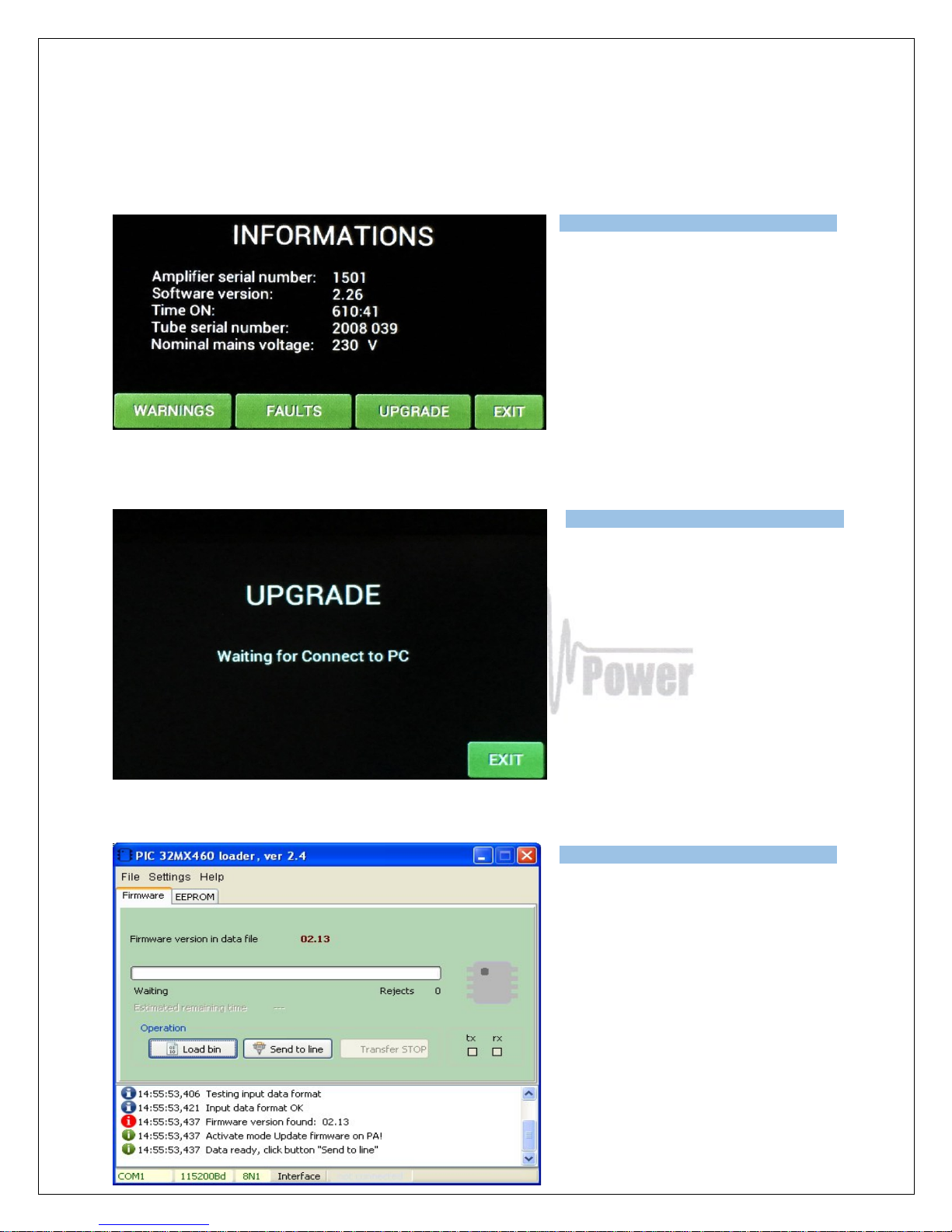
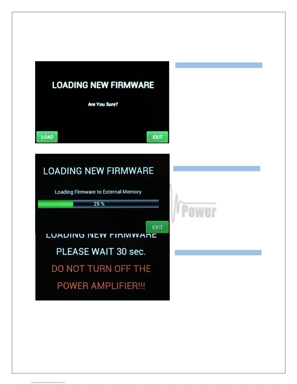
Press UPGRADE.
When you see this screen, go to PC
software and press button SEND TO
LINE.
Press SEND TO LINE.
Page 51
51
Press LOAD on OM2000A+ to start
loading.
You can see loading progress on the
bar graph
You will see this screen after
firmware was successfully loaded.
It is very important: Do not do any action. Wait until this screen disappears!
Usually, it takes about 30 seconds but sometimes it might take a little bit longer.
Page 52
52
At the end you will see main screen of OM2000A+. Switch PA OFF, disconnect serial cable and
you are ready to use OM2000A+ with the new firmware.
Page 53
53
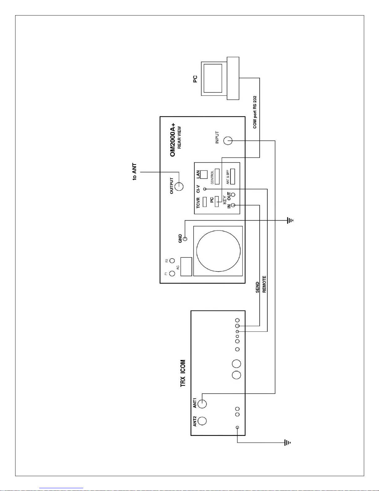
7.7. ICOM connection with OM2000A+
Page 54
54
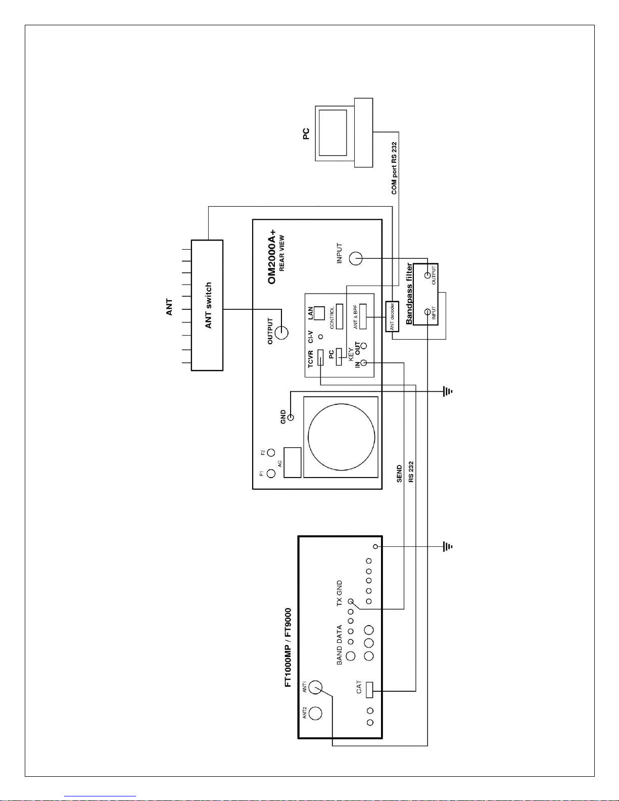
7.8. Yaesu plus BPF plus ANT Switch connection with OM2000A+
Page 55
55
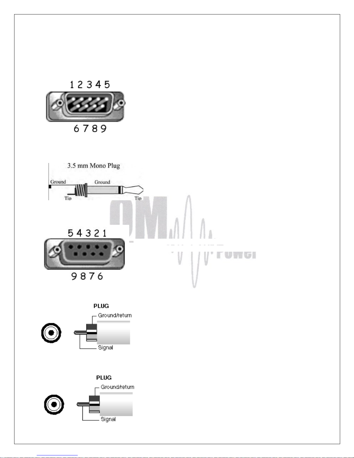
7.9. Control panel (rear side) connectors pin-out
TCVR connector DB 9 male
RS232 connection with TCVR. For CAT communication you need
connect pin 2 RX-D, pin 3 TX-D and pin 5 GROUND
CI-V connector
Use CI-V connection for communication with ICOM type
transceiver. Signal CI-V is connected to the Tip.
PC connector DB 9 female
RS232 connection to the computer. For CAT communication you need
connect pin 2 TX-D, pin 3 RX-D and pin 5 GROUND
KEY IN – RCA connector
Input signal PTT switching voltage / current 5V /2mA)
KEY OUT – RCA connector
Output signal PTT (maximum switching of 30V / 50mA)
Page 56
56
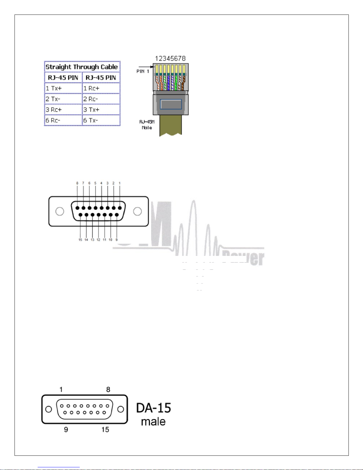
LAN connector
Use for connection to the LAN or WAN network.
CONTROL connector D-sub 15 female
Pin 1 - GROUND
Pin 2 - KEY OUT - ouput signal PTT ( maximum switching of 30V / 50mA
Pin 3 - KEY IN - input signal PTT – switching voltage / current 5V / 2mA
Pin 4 - CI-V - CI-V input for Icom CAT. The same as CI-V jack connector
Pin 5 - BAND data A input - input BCD Yaesu compatibile code from TCVR - bit 0
Pin 6 - BAND data B input - input BCD Yaesu compatibile code from TCVR - bit 1
Pin 7 - BAND data C input - input BCD Yaesu compatibile code from TCVR - bit 2
Pin 8 - BAND data D input - input BCD Yaesu compatibile code from TCVR - bit 3
Pin 9 - GROUND
Pin 10 - CI-V SW - connect to Ground if you use CI-V input on pin 4. Not used for CI-V with Jack
3,5mm
Pin 11 - IC band data - Icom Band data input. Band data information from ICOM TCVR
Pin 12 - INHIBIT - Inhibit output for TCVR. +12V/2mA inhibit transmit, 0 V if transmit is allowed
Pin 13 - No connect
Pin 14 - No connect
Pin 15 - No connect
ANT / BPF Connector - D-sub 15 male
Page 57
57
Pin 1 - ANT data D - output BCD code - bit 3 for antenna switching
Pin 2 - ANT data C - output BCD code - bit 2 for antenna switching
Pin 3 - ANT data B -- output BCD code - bit 1 for antenna switching
Pin 4 - ANT data A - output BCD code - bit 0 for antenna switching
Pin 5 - Not connected
Pin 6 - GND
Pin 7 - GND
Pin 8 - +5V 100mA - output supply 5V maximum 100 mA for antenna switch OM SW 1/10 equipped with
BCD decoder, +12V / 100mA ( in the amplifier after May 2017) usable to supply external antenna switch OM
SW 1/10+
Pin 9 - BAND data A - output BCD Yaesu BAND data compatible code. Use for automatic bandpass filter
OM6BPF
Pin 10 - BAND data B - output BCD Yaesu BAND data compatible code. Use for automatic bandpass filter
OM6BPF
Pin 11 - BAND data C - output BCD Yaesu BAND data compatible code. Use for automatic bandpass filter
OM6BP
Pin 12 - BAND data D - output BCD Yaesu BAND data compatible code. Use for automatic bandpass filter
OM6BPF
Pin 13 - Not connected
Pin 14 - GND
Pin 15 - +5V 100mA or +12V / 100mA – the same as pin 8
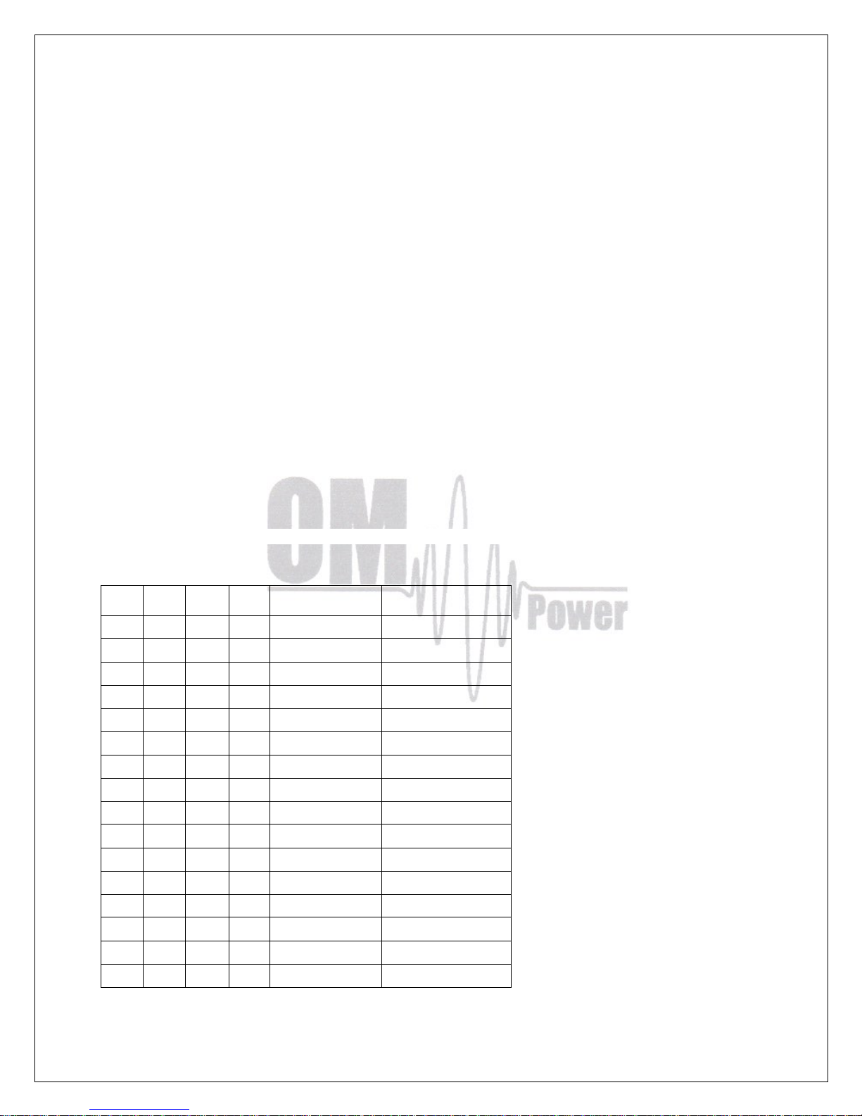
OM2000A+ can address up to 10 antenna port, see antenna BCD code table below
D C B A Logic value
Antenna port
0 0 0 0 0
UNDEFINED
0 0 0 1 1
ANT 1
0 0 1 0 2
ANT 2
0 0 1 1 3
ANT 3
0 1 0 0 4
ANT 4
0 1 0 1 5
ANT 5
0 1 1 0 6
ANT 6
0 1 1 1 7
ANT 7
1 0 0 0 8
ANT 8
1 0 0 1 9
ANT 9
1 0 1 0 A
ANT 10
1 0 1 1 B
UNDEFINED
1 1 0 0 C
UNDEFINED
1 1 0 1 D
UNDEFINED
1 1 1 0 E
UNDEFINED
1 1 1 1 F
UNDEFINED
Page 58
58
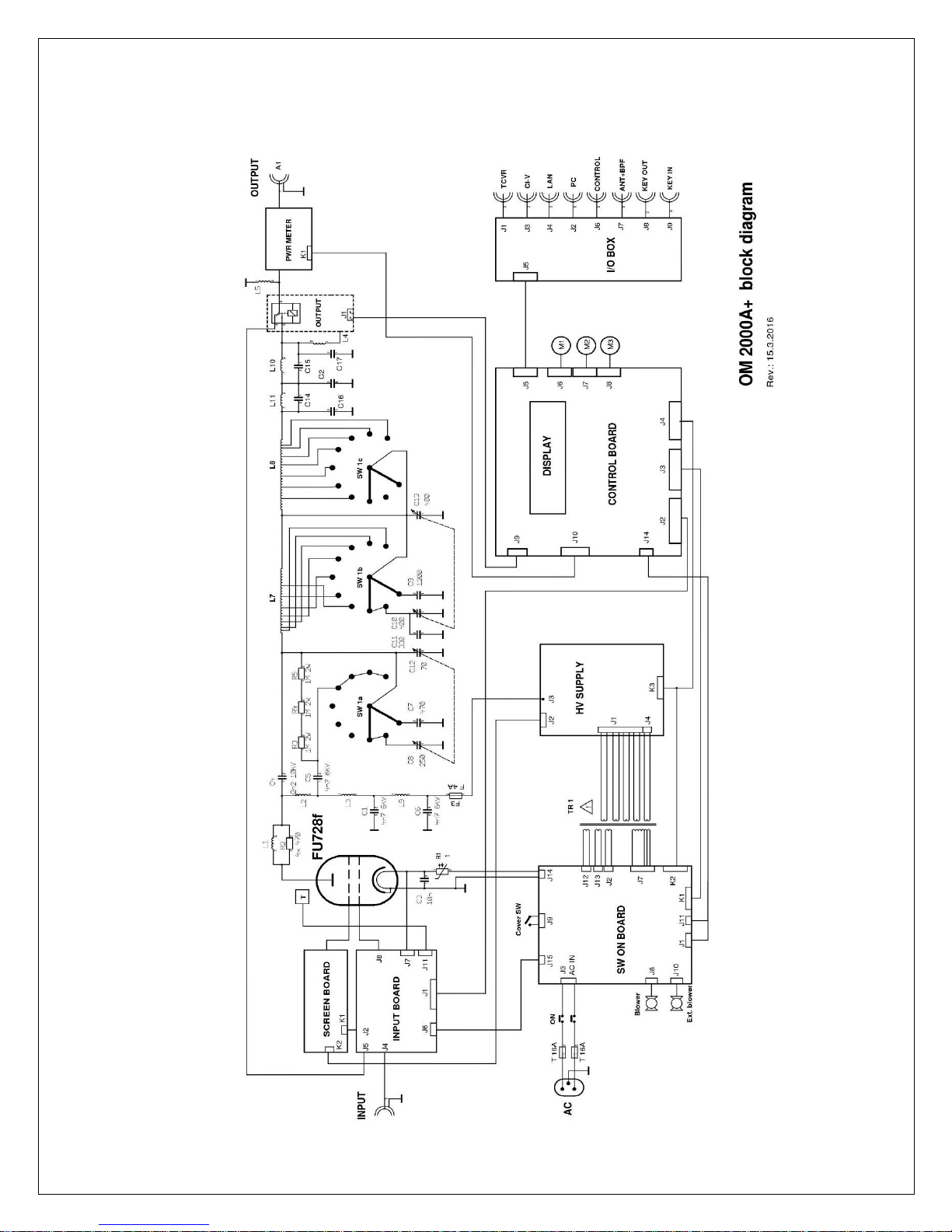
7.10. Block Diagram of the OM2000A+ Power Amplifier
Page 59
59
7.11 Troubleshooting
The OM2000A+ power amplifier contains several protection circuits, which checked operation.
In the case when some of parameters exceeds normal level, WARNING appears in the LAST
EVENS window with yelllow back colour. If some of parameters exceeds critical level, FAULT is
activated and the PA automatically switch to STBY mode. In the LAST EVENTS window with
red back colour fault information will appear.
All of these events are written to the FAULT and WARNING memories. Last event is visible
after LAST EVENTS button pressing together with information about possible causes.
There are several warning or fault messages possible to appear on the display:
Warning / Fault
Action
Description
Power Out is too high
Reduce input power
Output power exceeds maximum level, reduce the
input power.
Refl. power too high
Check your antenna
Reduce output power
Reflected power exceeds maximum allowed level.
Check if proper antenna is connected. In the case of
higher SWR reduce the input power and thus the
output and reflected power will be lower.
SWR is too high
Check your antenna
Check antenna switch
Antenna SWR is too high (SWR 3 for WARNING and
SWR 5 for FAULT). Check if proper antenna is
connected. Check antenna switch configuration, resp.
If you want to use antenna with higher SWR, this
protection can be switch off (page 25). But reflected
power will stay checked (max.350W).
Power In is too high
Reduce input power
Check amplifier tunning
At the PA input is too high input power – decrease it!
If maximum output power is not achievable, check
plate voltage and PA tuning.
Low output power
(tune)
Tune mistake.
Tune your amplifier
The PA has lower gain, may not be properly tuned.
Check plate voltage and Screen current. If they are ok,
make optimal tuning of the PA.
Plate current too high
Reduce input power
Check amplifier tunning
Check EBS setting
Plate current too high may be for the following
reasons:
• Too high input power – reduce it
• Improper tuning of the PA – bad antenna
impedance matching. Tune the PA properly.
• Improper BIAS setting. Check EBS1 and
EBS2.
Grid current is high
Reduce input power
Check amplifier tunning
Grid current too high is due to overdriving the PA.
Reduce the input power. If maximum output power is
no reachable due to high plate current, check the PA
tuning.
Screen current error
Reduce input power
Check amplifier tunning
Check plate voltage fuse
High screen current is usually of the following reasons:
• Overdriving the PA – reduce the input power
• Improper PA tuning. At maximum output power
the screen current must be inside the range of
0 mA to +30 mA.
• Plate voltage is missing. Press PTT without
driving If screen current is higher than +5mA,
check plate fuse (page 32).
Page 60
60
Plate voltage error
Check plate power supply
High voltage supply fault. Check fuses on HV board.
Grid voltage is low
Check grid power supply
Low voltage on the grid. Check fuse F4 on SW ON
board.
Screen voltage error
Check screen power supply
Check fuse F5 on HV supply board and fuse F1 on the
screen board.
Amplifier is too hot
Check cooling system
Set up aditional blower
Check the airflow (ventilation grid on the rear panel).
Cooling exhaust must be free – no obstacle within
15cm. During long contest set additional blower
ALLWAYS ON (page 18).
HARD FAULT
Check HV circuits and Tube
Protection circuit saved HV against overload. I the
case of too high current from the HV supply the HARD
FAULT protection is activated and switched the PA
automatically OFF. Check HV circuits, blocking
capacitors and the tube.
Heating voltage error
Set up properly transformer
voltage selector
Usually is due to improper setting of the primary
voltage on the transformer (page 33). In normal
condition Uf should be 9V +/- 0,3V.
Cooling error
Check blower rotation
Main blower lost the speed. Check its
functionality.
Mains error
Check mains voltage and set
up nominal mains voltage
Set up properly transformer
voltage selector
This error may be caused by the improper setting
of the nominal value of Um. Check your AC mains
voltage and set it as nominal Um (page 21).
Check primary voltage setting on the transformer.
This fault may occurs also in the case of very
“soft” mains, when during transmitting AC voltage
dropped down to very low level.
Factory reset
I the case of very abnormal behavior of OM2000A+ is possible to make factory reset. After that
all the parameters will be changed to the factory default values.
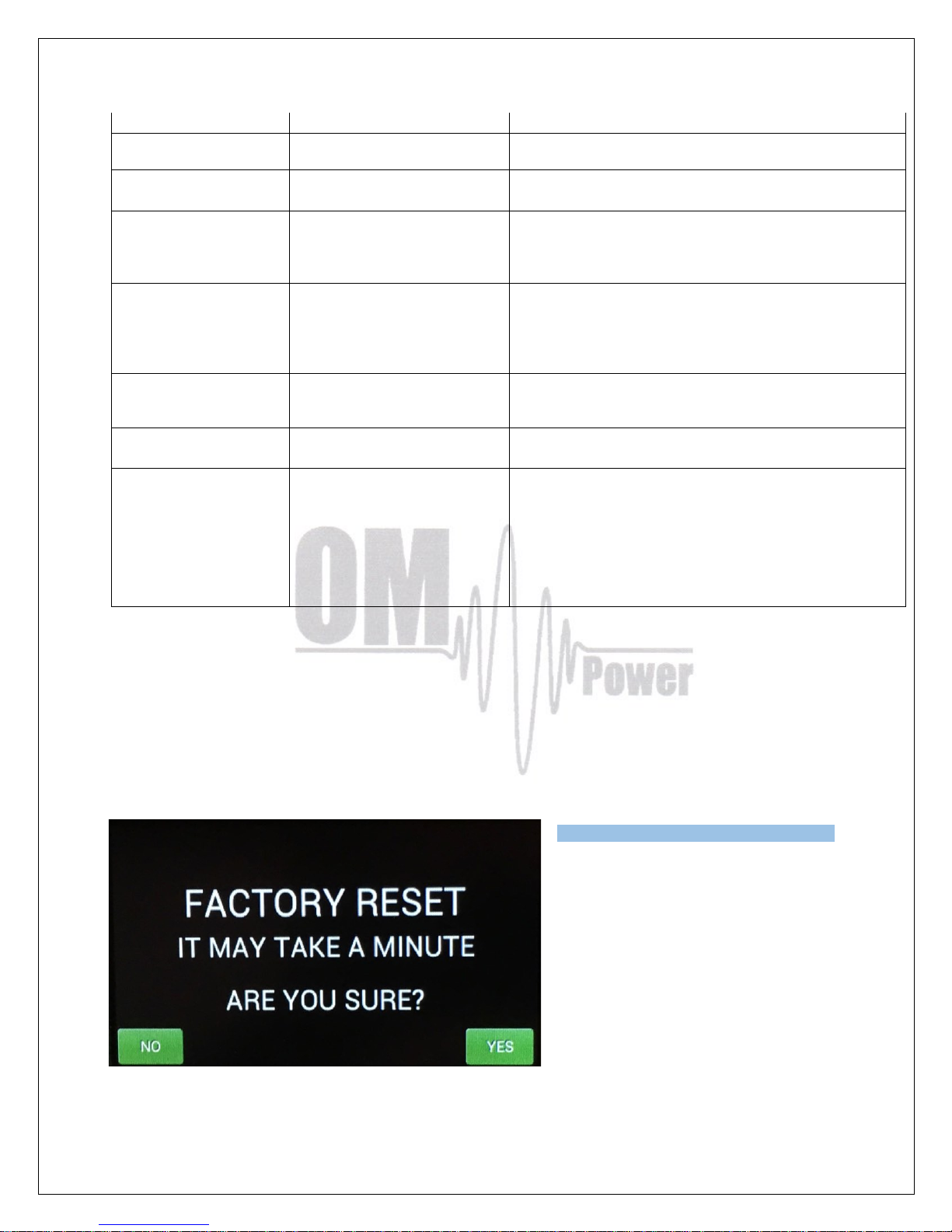
Press ON/OFF button, hold it and press Main switch. ON/OFF button hold pressed several
seconds, until next display will appear.
If you are sure to make factory reset,
press YES.
Page 61
61
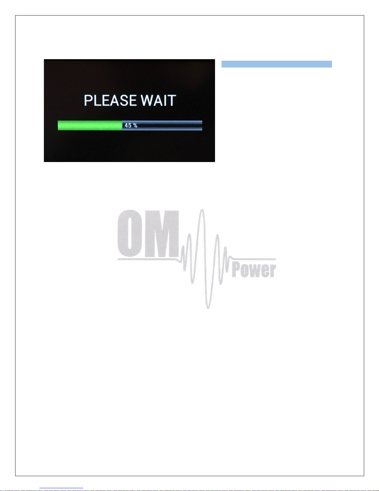
After finish the PA is ready for
operation.
Important notice: Perform Factory reset unless it is really necessary, because
subsequently you must recover all of personalized settings, mainly CAT communication
with TCVR, antenna switch settings etc.
 Loading...