

Page 1
Global Professional RC Model Brand
Installation Manual
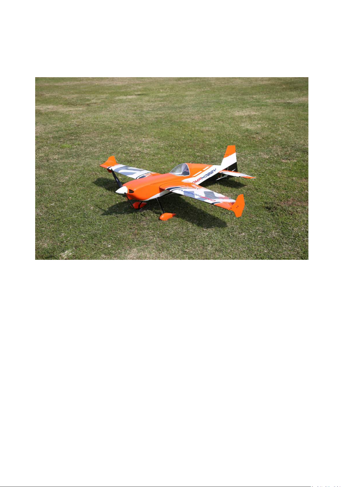
OMPHOBBY 60” 70E Edge 540 Kevlar Reinforced
Balsa Airplane
Zhuhai Edge Smart Drive Technology Co., Ltd.
www.omphobby.com
Page 2
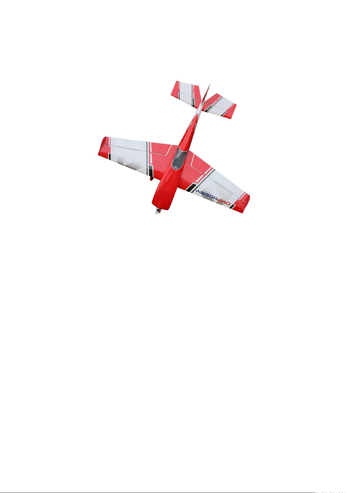
OMPHobby 60” Balsa Airplane
OMPHobby 60” 70E EDGE 540, not only has the low speed
stability, low stall point, excellent 3D performance, but also very
fast roll rate of traditional EDGE, and precise navigation control.
The traditional securing method of the motor base and the
landing skid base have been changed, preventing the loosening
of t he a nt i-gras p i ng nut. Win g , w i n g fen c e , n e w qu i c k
disassembly design, significantly reduced the installation time.
The horizontal tail and the fuselage are connected by a slot
Securing design, which increases the strength of the horizontal
tail and makes the installation more accurate and convenient.
Each aircraft has a metal nameplate with a unique serial number.
Zhuhai Edge Smart Drive Technology Co., Ltd.
www.omphobby.com
Page 3
OMPHobby 60” Balsa Airplane
Parameter Specification
Green-Black
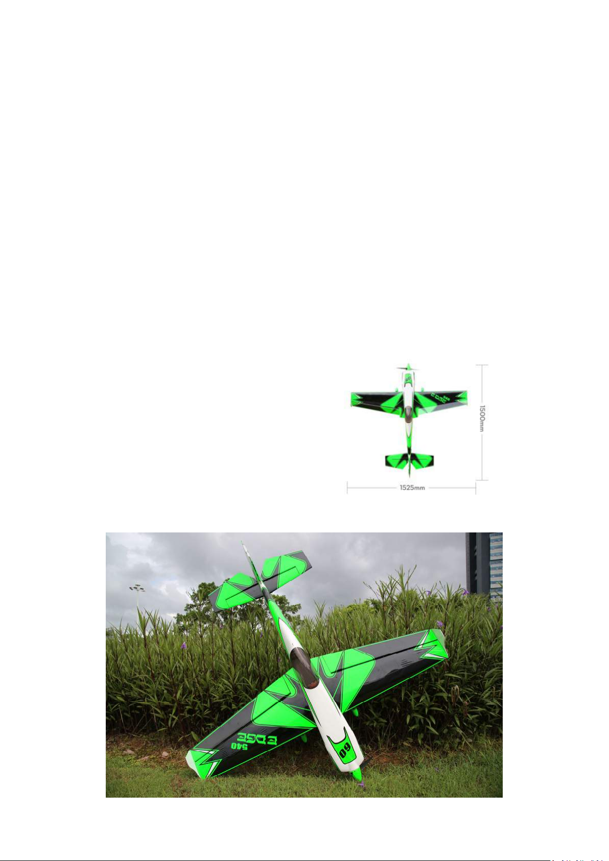
Item: OMPHOBBY 60”EDGE 540 Color Option
WingSpan: 1524mm(61in) Full Length: 1500mm(60in)
Red-White
Yellow-White
Orange-White
Flight Weight: 2.75~2.85KG
Wing Area:
Wing Angle of
Incidence:
Pack Dimension 130*44*22 (L*H*W)cm Gross Weight: 10KG
Servo: 13~15 Kg.cm*4 (Aileron*2,Elevator*1, Rudder*1)
Electric Power (Recommended):
Option 1: Option2:
Motor:
ESC:
Propeller: Eolo 15x8 Eolo 16x8
Lipos: 6s 3300mah-4000mah 6s 3300mah-4000mah
X4120 550KV 4125 515KV
80-100A 100A
42.32d㎡
0°
The Center of
Gravity (CG):
Wing Load:
Motor Thrust
Angles:
Approx.86-95mm
64.98~67.34g/d㎡
Down 0° & Right 2.8°
Zhuhai Edge Smart Drive Technology Co., Ltd.
www.omphobby.com
Page 4
OMPHobby 60” Balsa Airplane
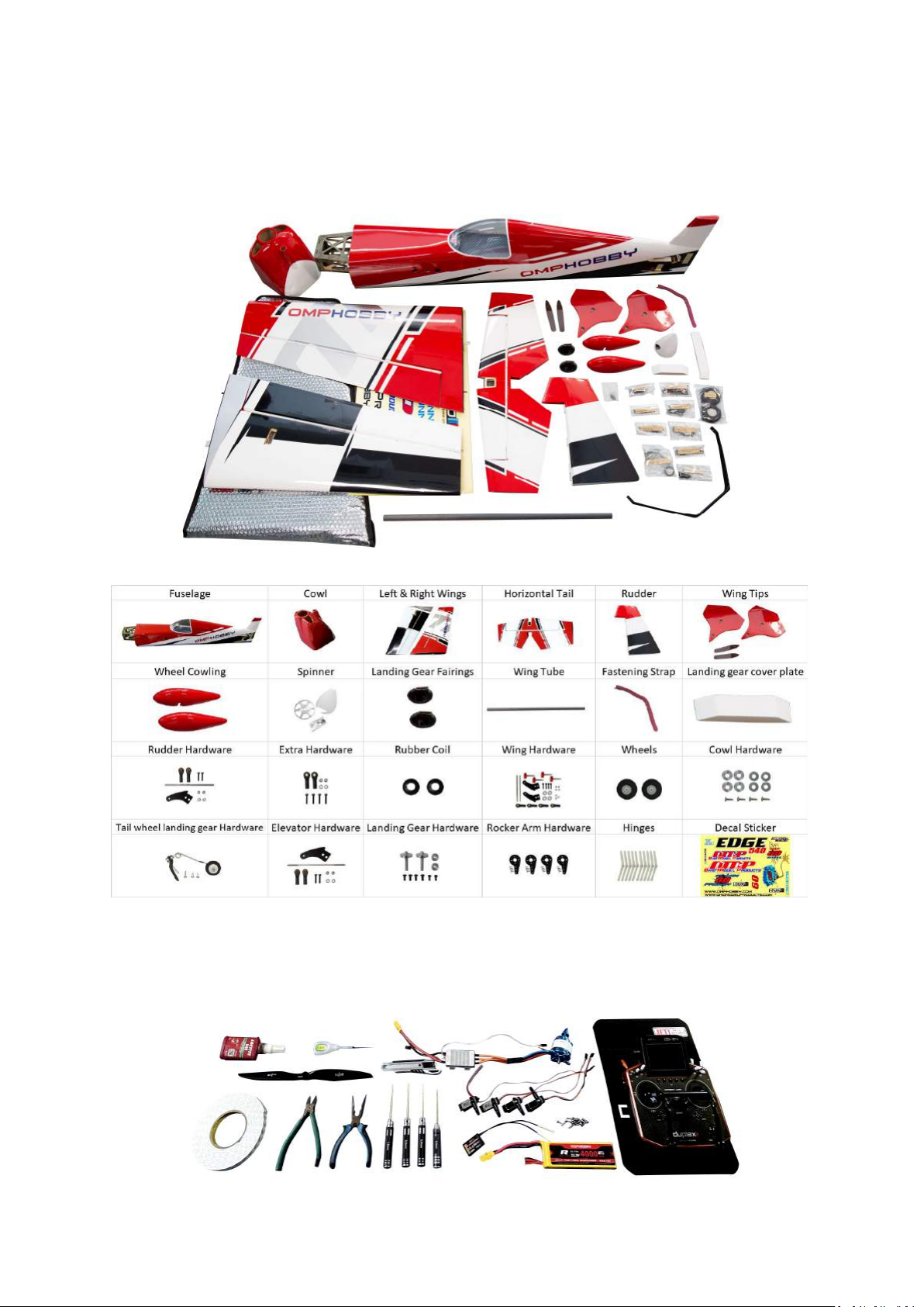
Ø Package contents (ARF version)
Ø Tools and Gear needed
Zhuhai Edge Smart Drive Technology Co., Ltd.
www.omphobby.com
Page 5
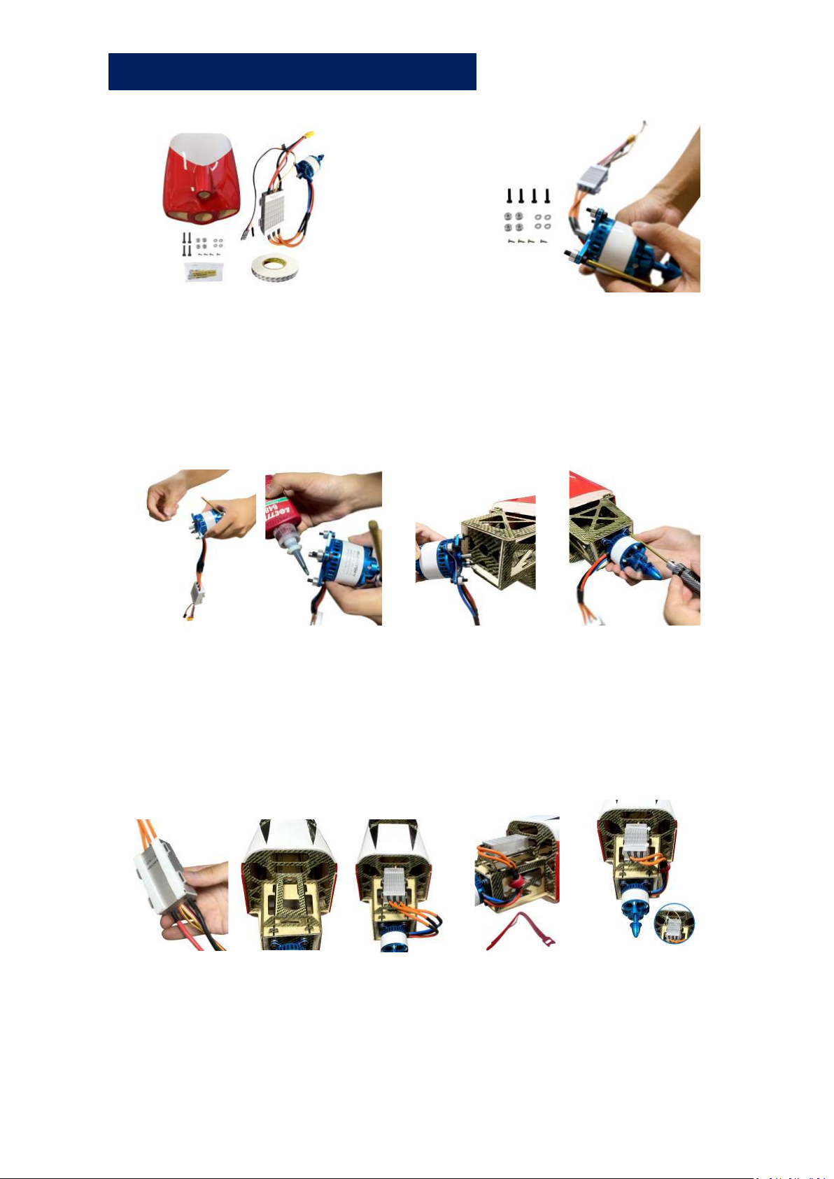
Cowl and Engine Assembly
Ø Motor Installation
1. Unscrew socket head screws from the head plate of fuselage.
2. Put the screws into motor mount and put aluminum columns
to the other side of screws.
3. Apply glue to the screws and install motor to motor holder.
Ø ESC Installation
1. Attach the connected ESC to ESC holder with double-sided tape
and Secure with cable ties.
2. Tie the wires of ESC and motor with fastening strap.
Zhuhai Edge Smart Drive Technology Co., Ltd.
www.omphobby.com
Page 6
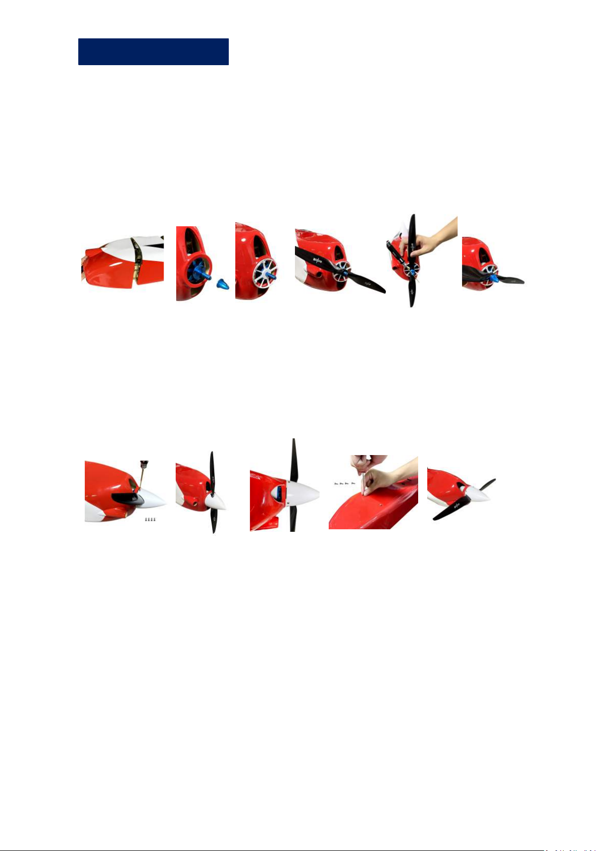
Cowl Part Assembly
Ø Cowl , Propeller, Spinner Installation
1. Install cowl to fuselage (please take note that motor
must be in center position)
2. Remove the propeller spinner adapter and screw gasket,
install the aluminum spinner back-plate, propeller,
propeller spinner adapter and screw gasket in
succession.
3. Secure the spinner with screws, please pay attention
that spinner must be located in the centre position of
the cowl, and spinner edge is parallel to the cowl, gap is
about 1.5mm.
4. Secure the cowl with screws, two screws for each of two
sides.secure
Zhuhai Edge Smart Drive Technology Co., Ltd.
www.omphobby.com
Page 7
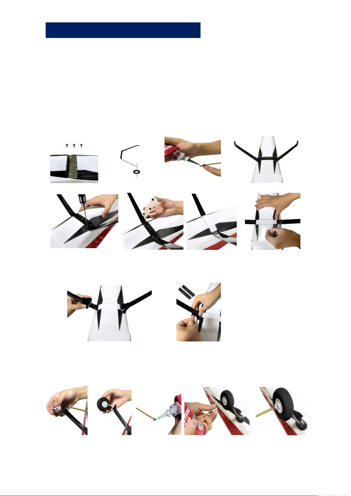
Landing gear Assembly
Ø Landing Gear Installation
1. Unscrew hexagon screws on the landing gear plate.
2. Apply glue to hexagon screws, use it to secure the carbon fiber
landing gear to landing gear plate.
3. Put landing gear cover plate into a slot and stick it with
transparent tape.
4. Install landing gear cuffs, Secure it with electrical tape.
5. Install wheels, Secure wheels with gasket and screw.
(Apply glue to screws)
Zhuhai Edge Smart Drive Technology Co., Ltd.
www.omphobby.com
Page 8
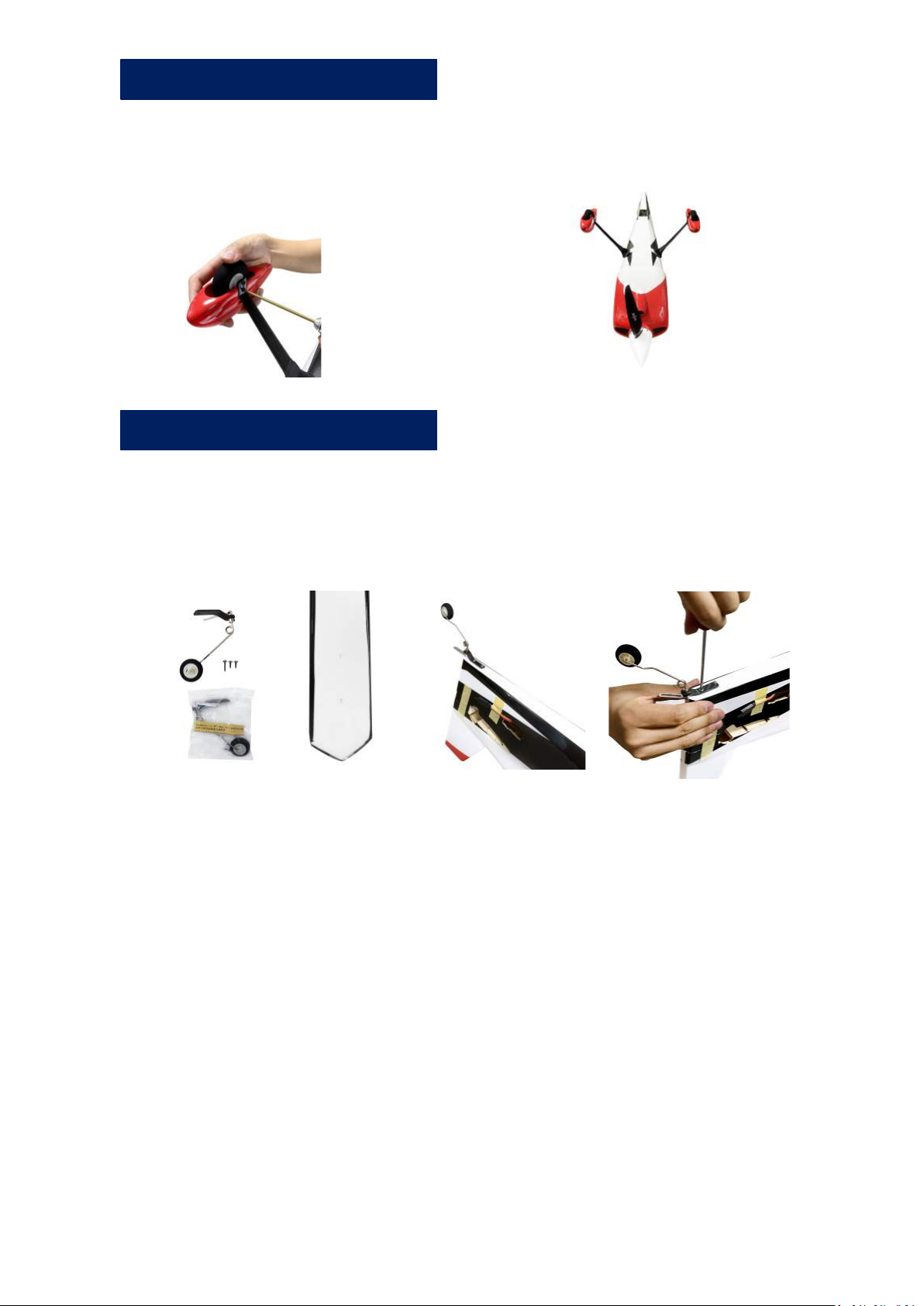
Landing gear Assembly
6. Install wheel cowls, tighten screws.
Tail wheel Assembly
Ø Tail Wheel Installation
1. Find the securing hole of the tail wheel frame, secure
the tail wheel bracket with screws.
Zhuhai Edge Smart Drive Technology Co., Ltd.
www.omphobby.com
Page 9
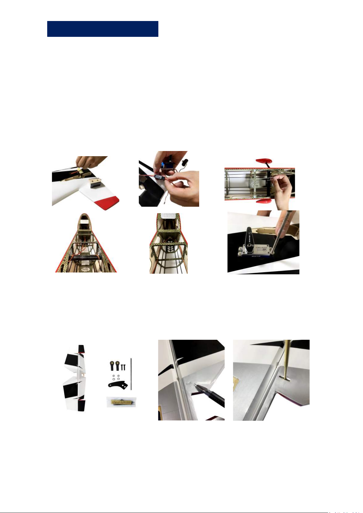
Elevator Assembly
Ø Elevator Servo Installation
1. Find a 60-core extension cable on the fuselage, tear off the
sticker, then connect it with elevator servo.
2. Find the white polyester thread in the fuselage frame, gently
pull it until the servo is placed into the opened servo hole.
3. Run the elevator servo extension wires through the conduit
located inside the fuselage and then place the extension wires
into frame holes.
4. Secure the servo using the screws.
Ø Horizontal Tail Installation
1. Carefully locate the slot which has been made on
horizontal tail, lightly cut through the covering but not
into the balsa sheeting.
Zhuhai Edge Smart Drive Technology Co., Ltd.
www.omphobby.com
Page 10
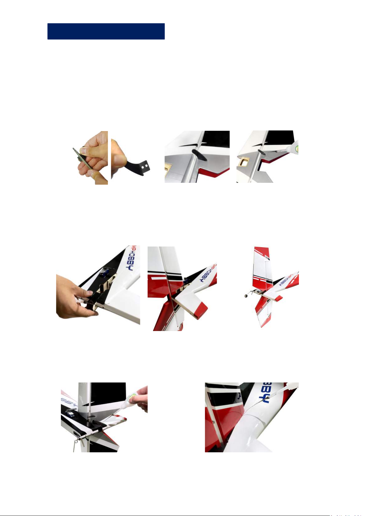
Elevator Assembly
Ø Horizontal Tail Installation
2. Use sand paper to roughen the root of control arm. Try to
insert it into the mounting slot to adjust the position at
first, then take it out, apply glue to the slot and the root
of the control arm, insert it to the slot to secure it.
3. Remove the secured plate used for filling the horizontal
tail slot, insert the horizontal tail into fuselage, please take
note that it must be fully inserted into the fuselage.
4. Insert secured plate to fill the horizontal tail slot, use 502
gluing the gap all around the horizontal tail.
Zhuhai Edge Smart Drive Technology Co., Ltd.
www.omphobby.com
Page 11
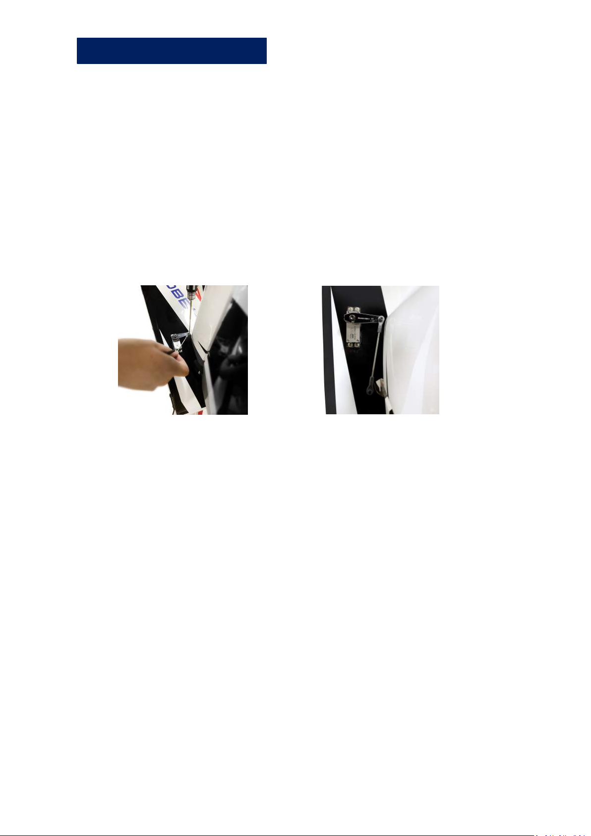
Elevator Assembly
Ø Horizontal Tail Installation
5. After the glue is dried, assemble the servo arm and
control horn with ball head pull rod, secure the cup head
hexagonal screw, gasket, ball head to the servo arm,
secure it with iron pliers, adjust the ball head pull rods to
proper length.
6. Secure screw, washer, ball head to control horn.
7. Check the angle between the servo arm and control horns.
(Make sure the control horn is at 90 degrees against
servo.)
Zhuhai Edge Smart Drive Technology Co., Ltd.
www.omphobby.com
Page 12
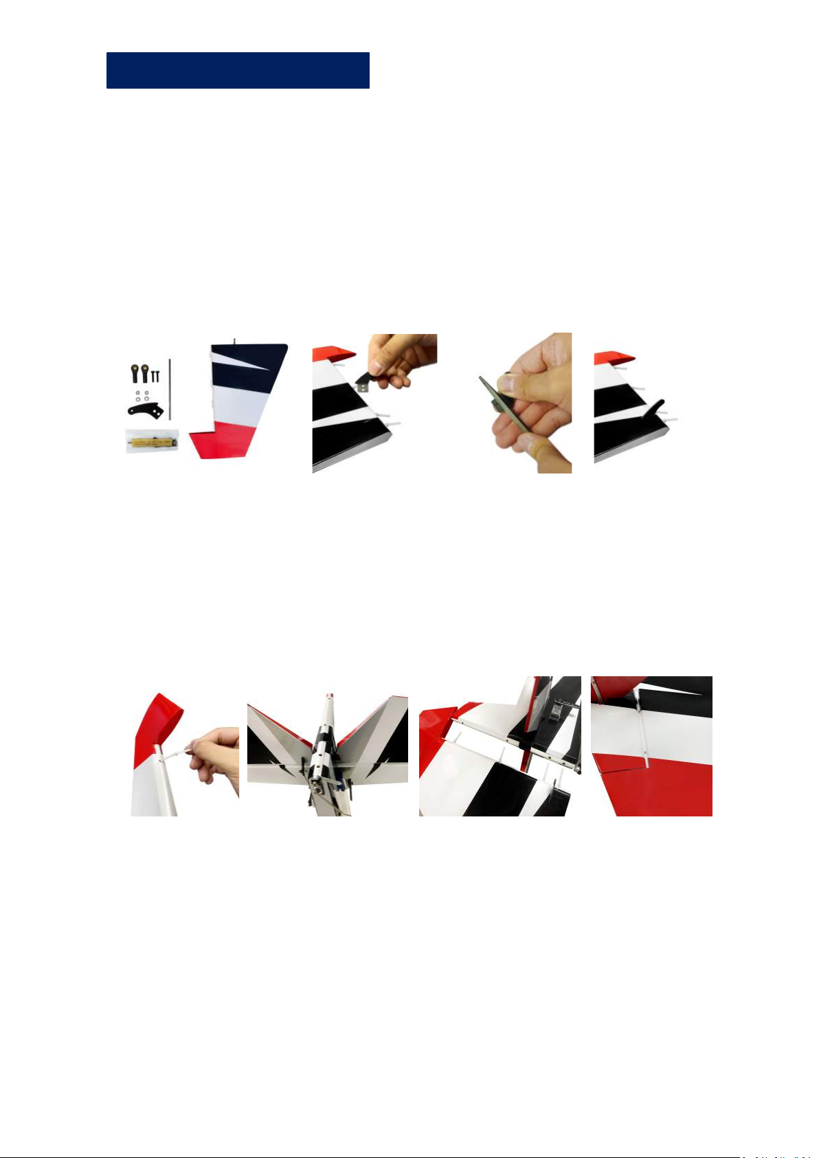
Rudder Assembly
Ø Rudder Installation
1. Carefully locate the slot which has been made on the vertical
tail, lightly cut through the covering but not into the balsa
sheeting.
2. Grind the root of control horns, try it first to insert it into the
slot to adjust the position, then take it out, apply glue to the
slot and the root of the control horn, insert it to the slot to
secure it .
3. Remove 4 hinges which are inserted in the rudder. Inject AB
glue into the holes, apply glue to 4 hinges with appropriate
length from its bottom,then insert 4 hinges into the rudder.
4. Inject AB glue into the holes in fuselage, apply glue to the
other end of hinges with appropriate length, then insert it into
fuselage.
Zhuhai Edge Smart Drive Technology Co., Ltd.
www.omphobby.com
Page 13
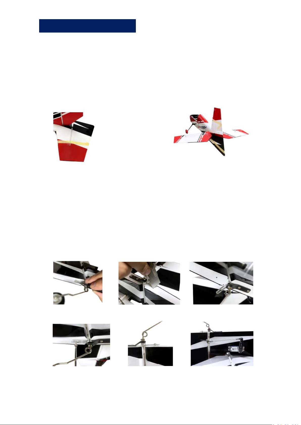
Rudder Assembly
6. Apply grease or engine oil on all joints between rudder and
fuselage, and around the hinges, to avoid affecting the
sensitivity of rudder after glue dried.
7. Tie rudder with masking tape while glue is still wet to
prevent loosening.
8. Make sure the shaft is in the middle position, and keep the
gap between rudder and fuselage within 1mm.
9. Find the center position to secure the tail wheel bracket to
rudder, drill a hole, secure the tail wheel bracket with screws.
(No need to fully screwed in)
10. After the glue is dried, secure the servo arm and control
arms with a ball head pull rod.
11. Make sure the angle of servo and control horns is 90° and
180°oblique, ensure rudder is symmetrical to the 2 sides of
fuselage.
Zhuhai Edge Smart Drive Technology Co., Ltd.
www.omphobby.com
Page 14
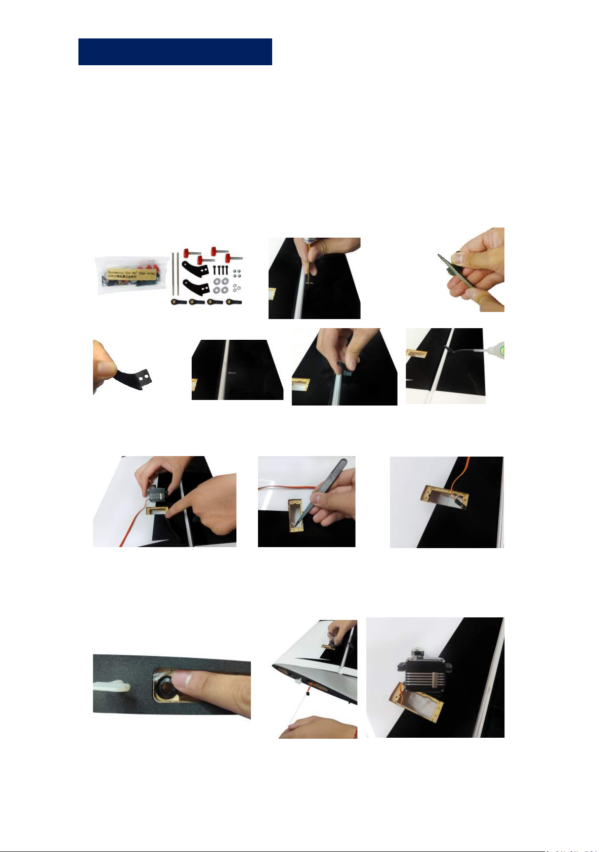
Wings Assembly
Ø Aileron Servo Installation
1. Carefully locate the slot which has been made on the wing
tail, lightly cut through the covering but not into the balsa
sheeting.
2. Use sand paper to roughen the root of control arm. Try to
insert it into the mounting slot to adjust the position at first,
then take it out, apply glue to the slot and the root of the
control arm, insert it to the slot to secure it.
3. Pull out the white polyester thread from the servo hole with
tweezers, tie up with aileron servo connector.
4. Find the other head of white polyester thread from wing side,
pull it until aileron servo is placed in servo hole.
Zhuhai Edge Smart Drive Technology Co., Ltd.
www.omphobby.com
Page 15
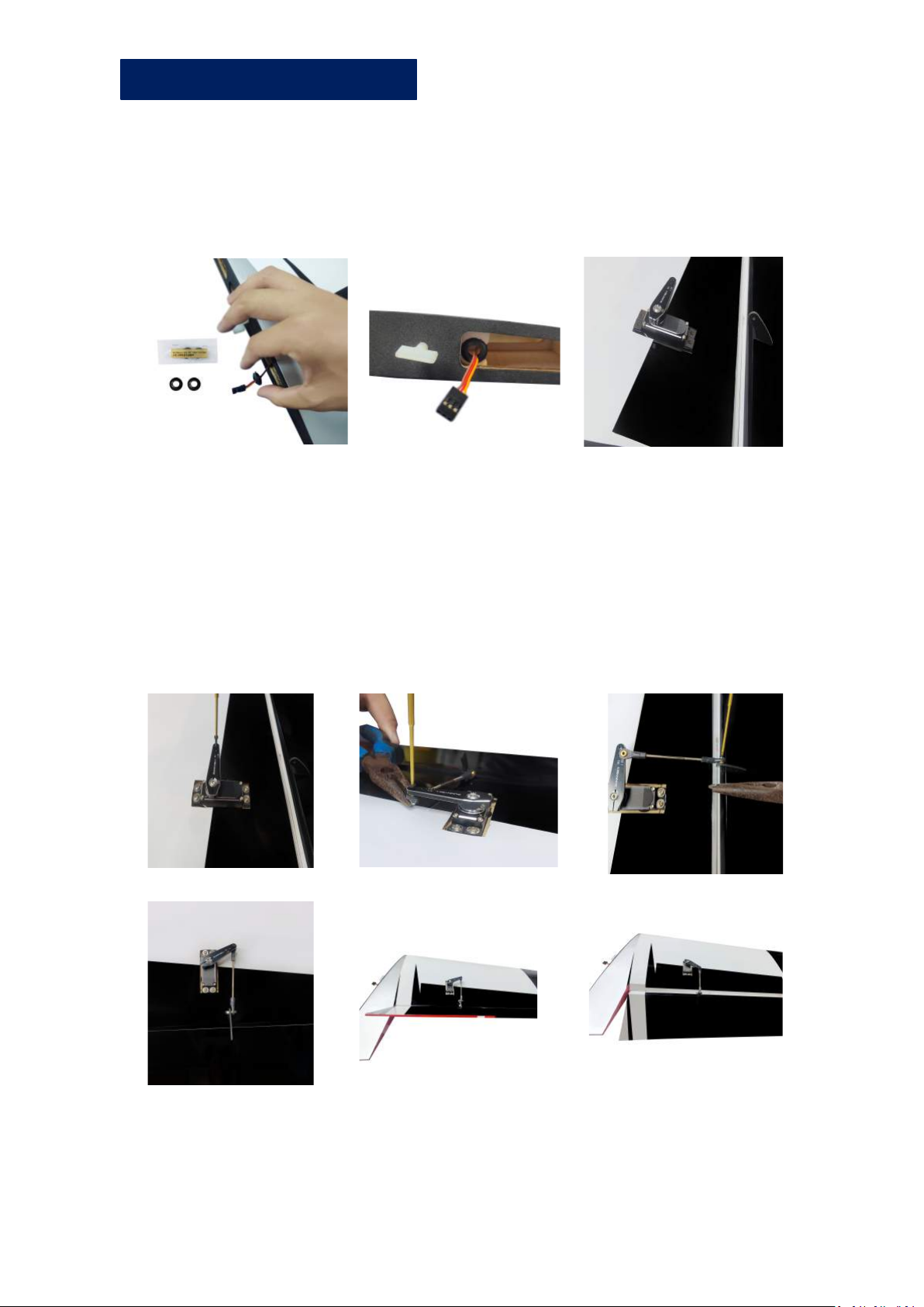
Wings Assembly
5. Remove black rubber ring from the wing side,pass
aileron servo wire into the black rubber ring and
secure it to the original position.
6. Secure aileron servo arm and control horns with ball head
pull rod, put the cup head hexagonal screw, gasket, ball head
on servo arm, secure it with iron pliers, adjust the ball head
pull rods to proper length.
7. Secure screw, washer, ball head to control arm, control arm is
at 90 degrees against servo.
8. Check the degrees between servo arm and control arms.
Zhuhai Edge Smart Drive Technology Co., Ltd.
www.omphobby.com
Page 16
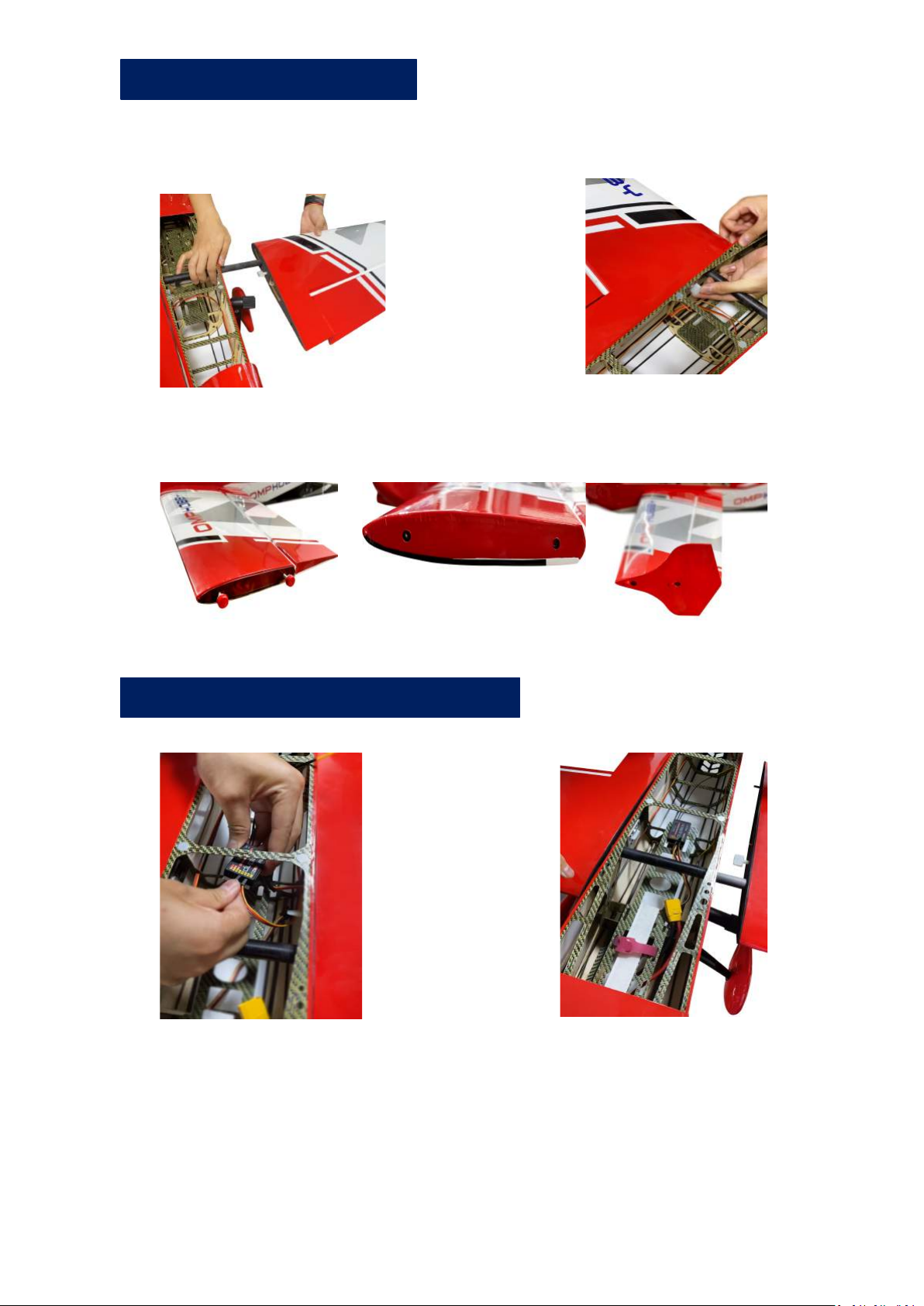
Wings Assembly
9. Assemble the wing tube into the fuselage then
install wings, turn white screws to secure the wings.
10. Unscrew the retaining screws on the wing, install wingtip.
Connect Receiver and Battery
Zhuhai Edge Smart Drive Technology Co., Ltd.
www.omphobby.com
Page 17
OMPHobby 60” Balsa Airplane
For customer support in the USA, please
contact Ohio Model Products in Ohio.
Tel: +1-614-733-9488 (9am -5pm, ET)
Email: [email protected]
Website: www.OhioModelProducts.com
For customer support outside of the USA,
please contact OMPHobby in China.
Email: [email protected]
Website: www.omphobby.com
Disclaimer and Safety
Ø This product is not a toy. It is not recommended for children under age 14.
Ø Fly the airplane by abiding by local laws and rules.
Ø Fly the airplane in a designated location, and always maintain visual contact of the aircra
ft.
Ø Avoid flying directly over unprotected people, moving vehicles, and occupied structures.
Ø Read the safe code of AMA before flight. The guideline can be downloaded from the foll
owing link: www.modelaircraft.org/files/100.pdf
Zhuhai Edge Smart Drive Technology Co., Ltd.
www.omphobby.com
 Loading...