

Page 1
Global Professional RC Model Brand
Installation Manual
Bushmaster 65” Balsa Airplane
Zhuhai Edge Smart Drive Technology Co., Ltd.
www.omphobby.com
Page 2
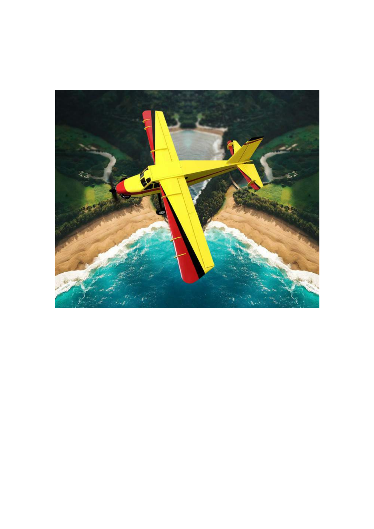
OMPHobby 65” Bushmaster
Balsa Airplane
OMPHobby Bushmaster 65 Inch aircraft, this aircraft faithfully
replicates the true designs of the real-life aircraft. The head of
the aircraft is reinforced with composite splints, the fuselage
uses carbon fiber beams, an easy-to-install Horizontal Stabilizer
Elevator, and an integrated Elevator. There are also pontoon
installation positions,and aluminum alloy Wing Struts. The
aircraft is made of high-quality materials such as balsa wood,
composite material, aluminum alloy, carbon fiber, and covering
film. lt is light, strong, and exquisitely beautiful.
Zhuhai Edge Smart Drive Technology Co., Ltd.
www.omphobby.com
Page 3
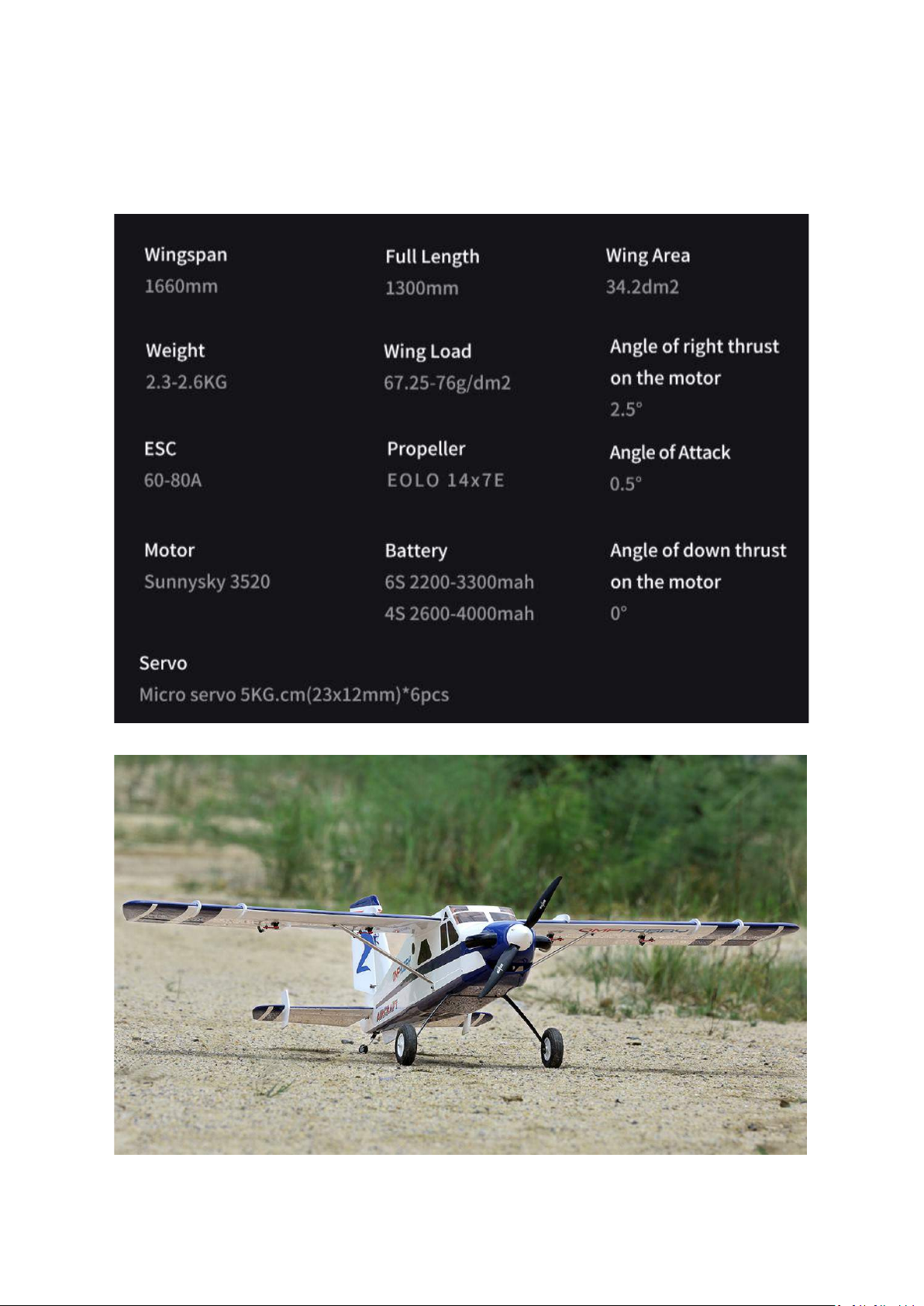
OMPHobby Bushmaster 65”
Balsa Airplane
Zhuhai Edge Smart Drive Technology Co., Ltd.
www.omphobby.com
Page 4
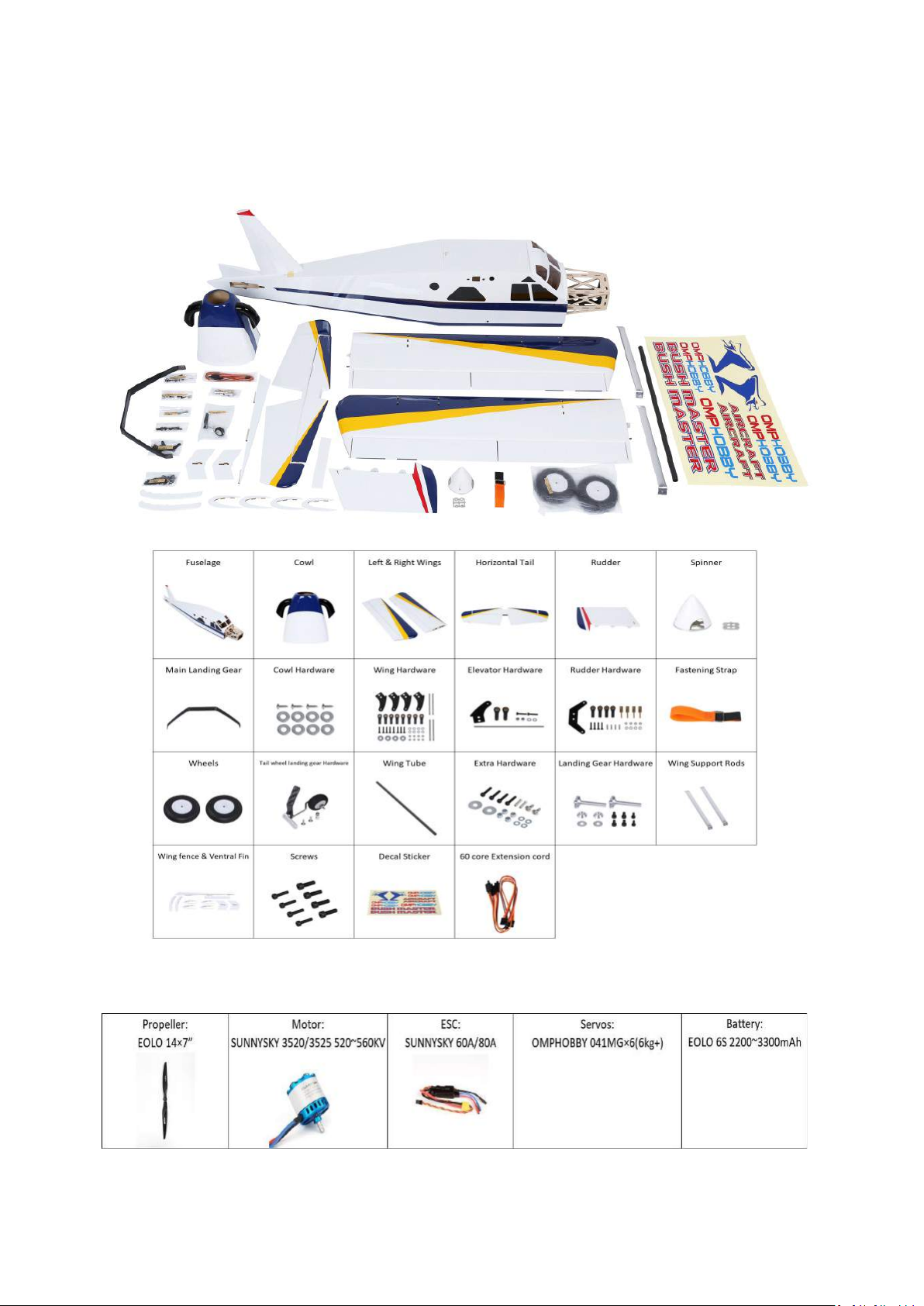
Bushmaster 65” Balsa Airplane
Ø Package contents (ARF version)
Recommended Power Systerms:
Zhuhai Edge Smart Drive Technology Co., Ltd.
www.omphobby.com
Page 5
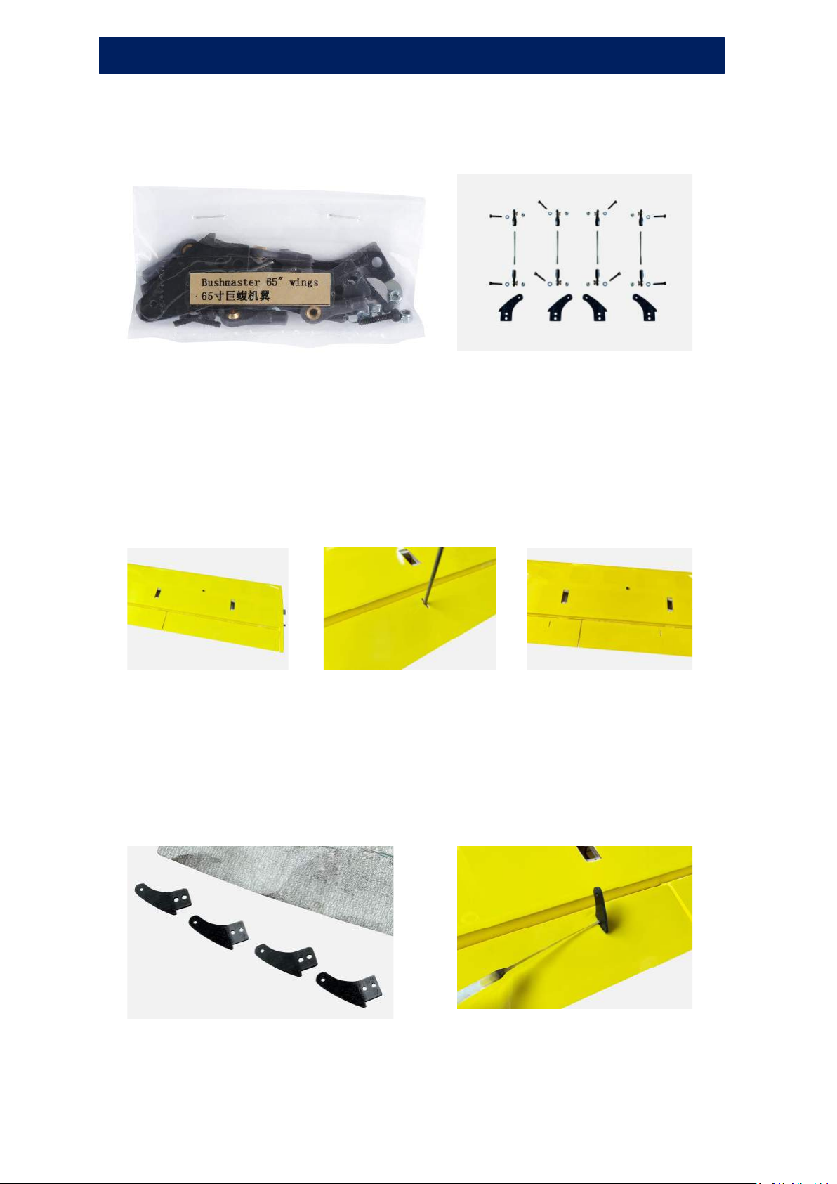
Wings Assembly
1. Take out wings hardware
2. Carefully locate the slots which has been made on aileron and
flap, lightly cut through the covering but not into the balsa
sheeting; Insert 2mm inner hexagon screwdriver into the slots
to make sure the glue inflow into the slots to secure the
control arms.
3. Use sand paper to roughen the root of control arms. Try to
insert it into the mounting slot to adjust the position at first,
then take it out, apply glue to the slot and the root of the
control arm insert it into the slot to secure it.
Zhuhai Edge Smart Drive Technology Co., Ltd.
www.omphobby.com
Page 6
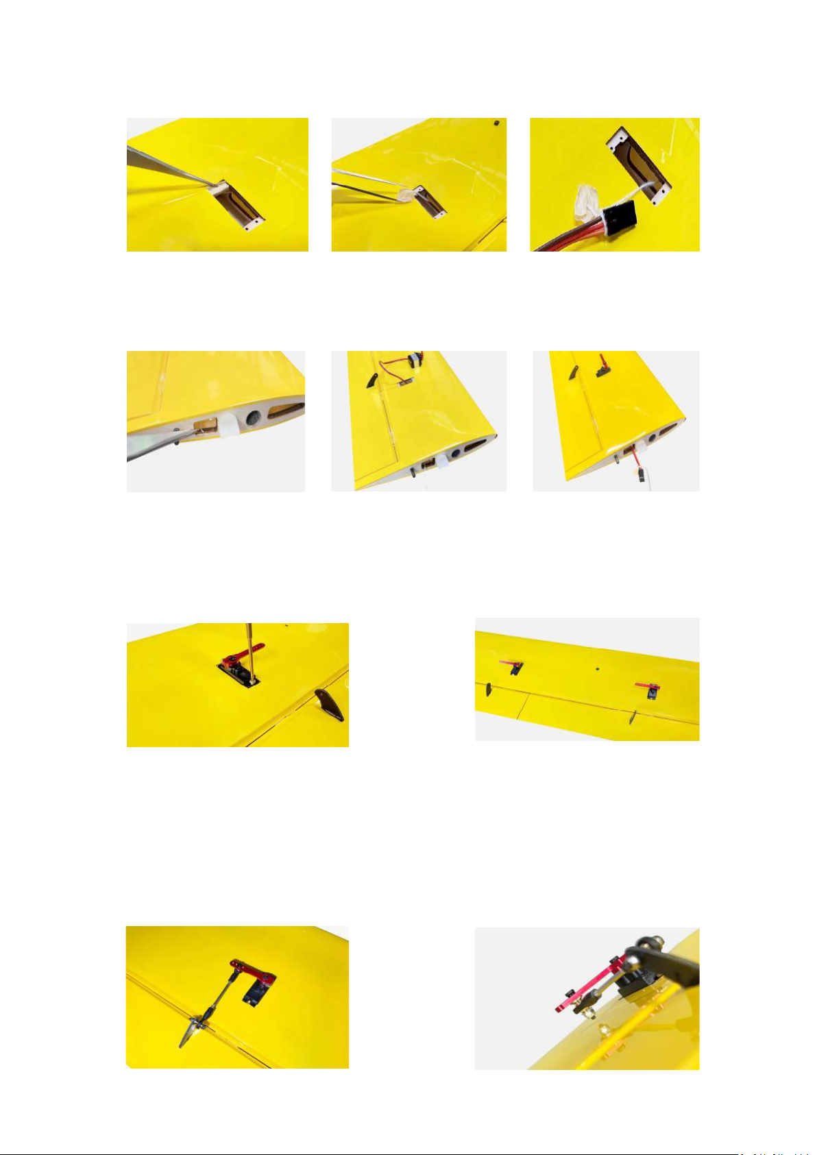
4. Pull out the white polyester thread from the servo holes with
tweezers,tie up with the servo connector.
5. Find the other head of white polyester thread from wing side,
pull it until servo is placed in servo hole.
6. Use 1.5mm internal hexagon screwdriver to tighten the M2 × 6
inner hexagon self-tapping screws to secure the servos.
Tip: Flap servo cord needs 450mm,Aileron servo cord needs 200mm
7. Secure servo arms and control arms with ball head pull rod
(After the glue is dried), put the cup head hexagonal screw,
gasket, ball head on servo arm, secure it with iron pliers, adjust
the ball head pull rods to proper length.
8. Secure screw, washer, ball head to control arm, check the
degrees between servo arms and control arms.
Zhuhai Edge Smart Drive Technology Co., Ltd.
www.omphobby.com
Page 7
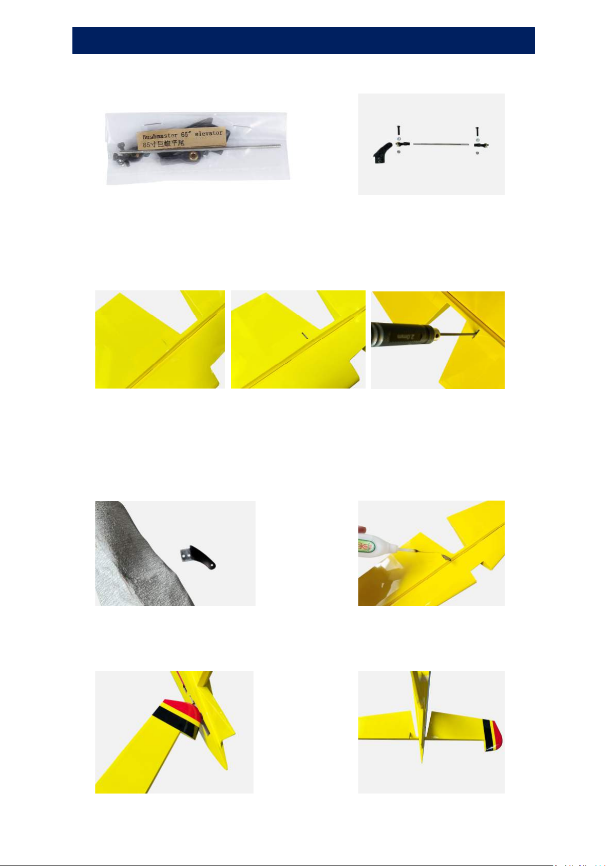
Elevator Assembly
1. Take out Elevator Hardware
2. Carefully locate the slot which has been made on horizontal tail,
lightly cut through the covering but not into the balsa sheeting;
Insert 2mm inner hexagon screwdriver into the slot to make
sure the glue inflow into the slot to secure the control arms.
3. Use sand paper to roughen the root of control arms. Try to
insert it into the mounting slot to adjust the position at first,
then take it out, apply glue to the slot and the root of the
control arm, insert it into the slot to secure it.
4. Insert elevator into the fuselage from the opposite direction
and its reverse side as in Figure:
Zhuhai Edge Smart Drive Technology Co., Ltd.
www.omphobby.com
Page 8
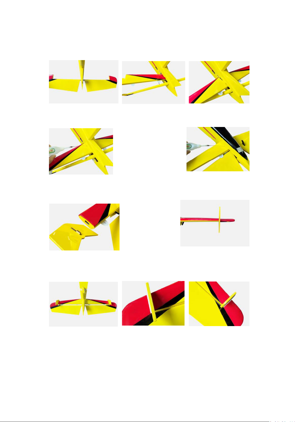
5. Turn the elevator over after it inserted into the fuselage, then
insert the horizontal tail into fuselage, the horizontal tail slot
must be fully inserted into the fuselage slot.
6. Use 502 gluing the gap all around the horizontal tail.
7. Install the Wing fences as in Figure, make sure the wing
fences are perpendicular to the horizontal tail.
8. Insert the elevator hinges into the horizontal tail hinge slots,
make sure the gap on the left and right sides is the same.
Zhuhai Edge Smart Drive Technology Co., Ltd.
www.omphobby.com
Page 9
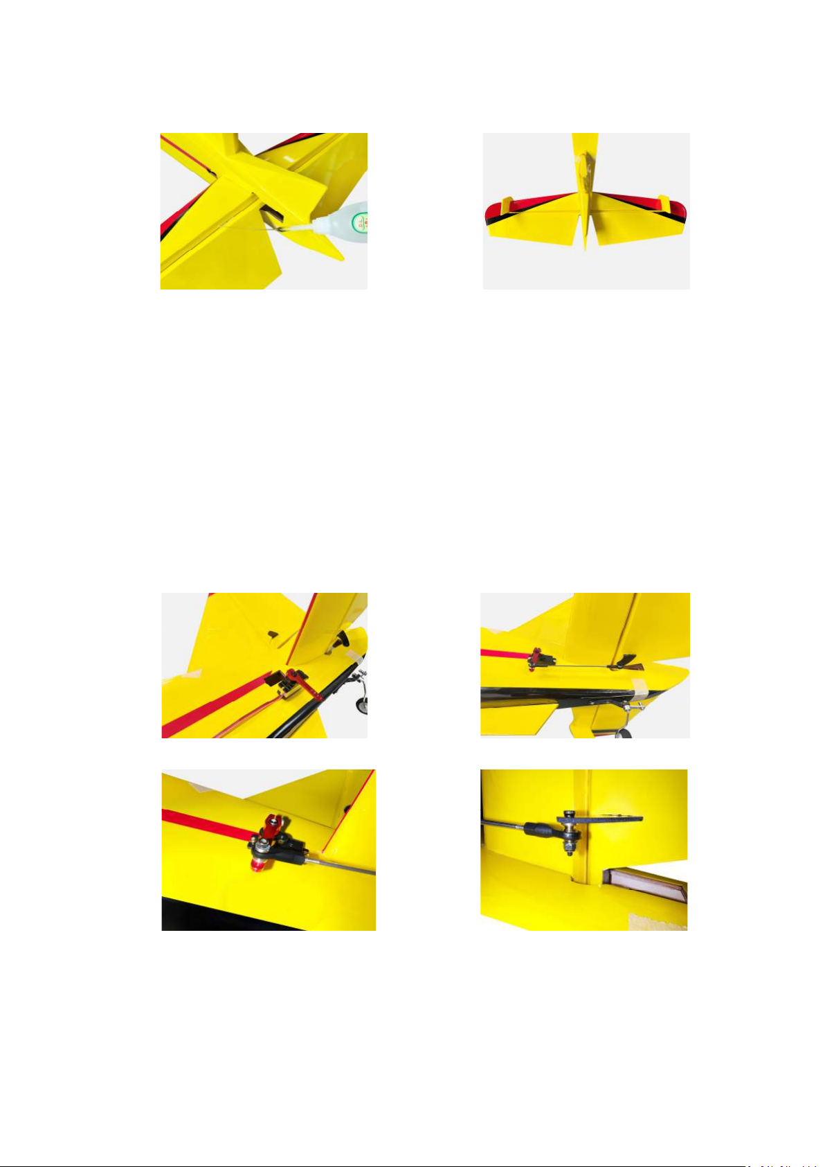
9. Between the horizontal tai and elevator leave a 0.5mm gap
and apply glue to the hinges.
10. After the glue is dried, install elevator servo, assemble the
servo arm and control arm with ball head pull rod, secure
the cup head hexagonal screw, gasket, ball head to the
servo arm, secure it with iron pliers, adjust the ball head
pull rods to proper length.
11. Secure screw, washer, ball head to control arm.
12. The mounting locations of elevator servo and Ball head pull
rod as in Figure.
Zhuhai Edge Smart Drive Technology Co., Ltd.
www.omphobby.com
Page 10
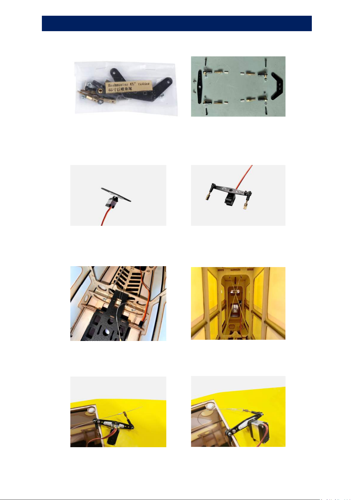
Rudder Assembly
1. Take out Rudder Hardware
2. Secure the servo arm extended gasket to servo arms with T2 ×
6 self-tapping screws, then install the ball head screws, metal
regulators and steel wires connecting rods as in Figure.
3. Find two steel wires in the fuselage, pay attention to crossinstall the steel wires as in Figure
4. Thread the steel wires into the connecting rods and install
it as in Figure
Zhuhai Edge Smart Drive Technology Co., Ltd.
www.omphobby.com
Page 11
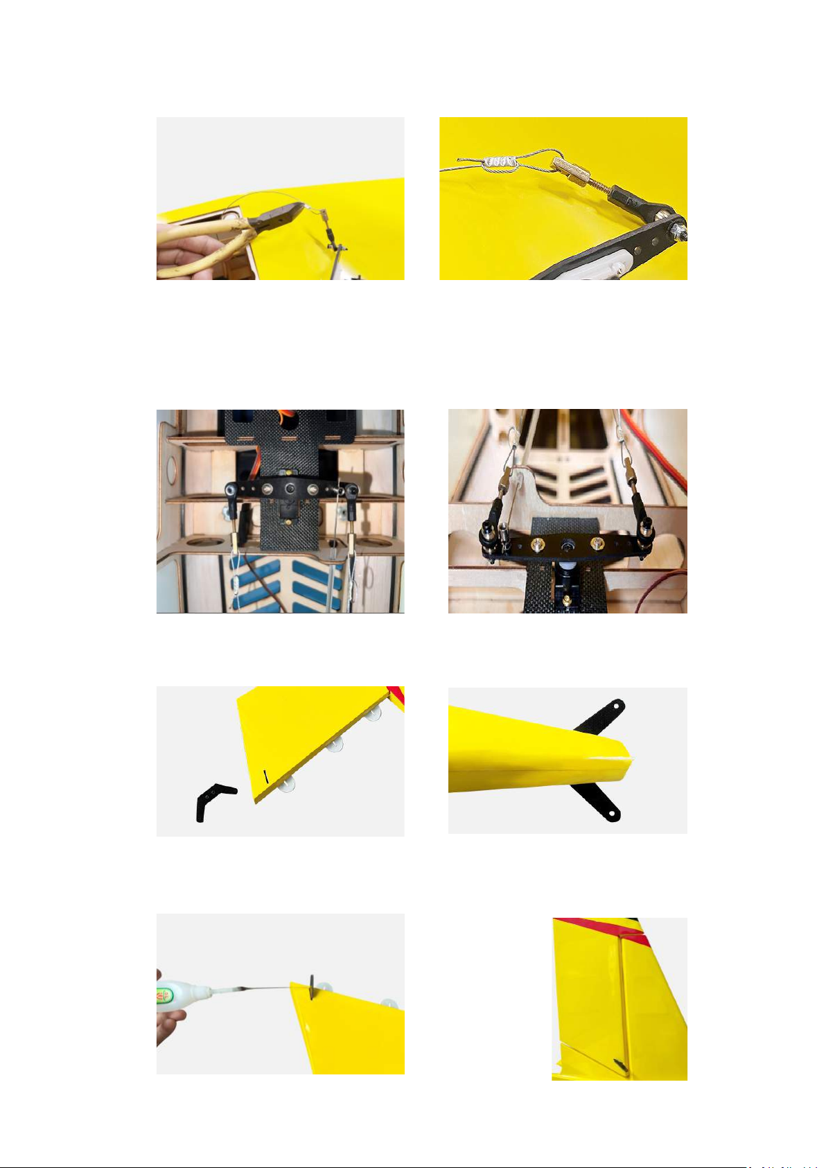
5. Use diagonal pliers to compress the copper sleeve tightly as in
Figure
6. Install rudder servo as in Figure, thread the tail wheel control
steel wire into the metal regulators, secure rudder servo with
screws to the plate, use a 1.5mm inner hexagon screwdriver
tighten the metal regulator
7. Insert the rudder control arm into the rudder as in Figure,
adjust it to ensure the left and right sides are consistent.
8. Apply glue to the control arm, insert the rudder hinges into
the vertical tail hinge slots, make sure the gap is about 0.5mm
Zhuhai Edge Smart Drive Technology Co., Ltd.
www.omphobby.com
Page 12
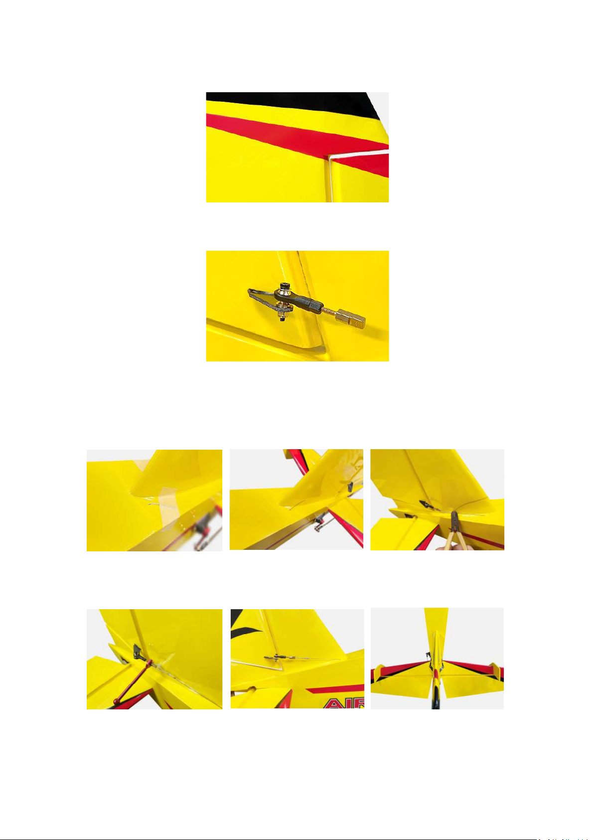
9. Align the rudder pattern to vertical tail pattern, then apply
glue to the hinges for both sides.
10. The installation of the rudder control arm and ball head screws
as in Figure
11. Find the rudder steel wire at the root of the vertical tail, tear off
the tape, thread the steel wire into the connecting rods and
fasten it the same way as before, use diagonal pliers to compress
the copper sleeve tightly as in Figure,cut off the extra steel wire.
12. Use a 4mm open wrench to adjust the tightness and level,make
sure the wires are tightened and two sides are symmetric.
Zhuhai Edge Smart Drive Technology Co., Ltd.
www.omphobby.com
Page 13
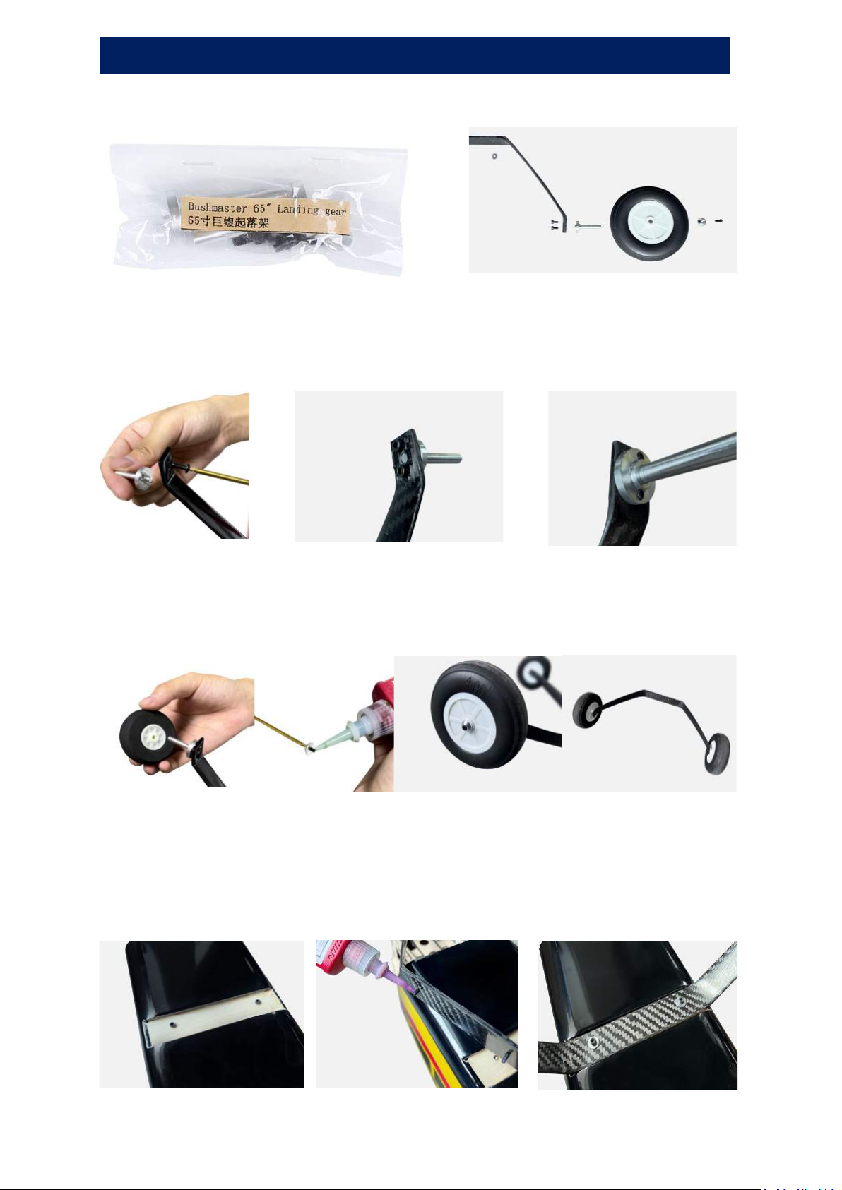
Main wheel assembly
1. Take out the Main wheels and landing gear hardware
2. Put two M3 x 6mm black cup head hexagon screws into the
landing gear, then apply thread locking Adhesive-Low Strength
to the screws, tighten wheel axle with the screws as in Figure
3. Install main wheels, secure wheels with gaskets and screws.
(Apply thread locking Adhesive-Low Strength to the screws
then tighten it)
4. Unscrew the M3 x 12mm black cup head hexagon screws from
the landing gear plate with a 2.5mm screwdriver, then put it into
the landing gear, apply thread locking Adhesive-Low Strength to
the screws, tighten the screws to secure the landing gear.
Zhuhai Edge Smart Drive Technology Co., Ltd.
www.omphobby.com
Page 14
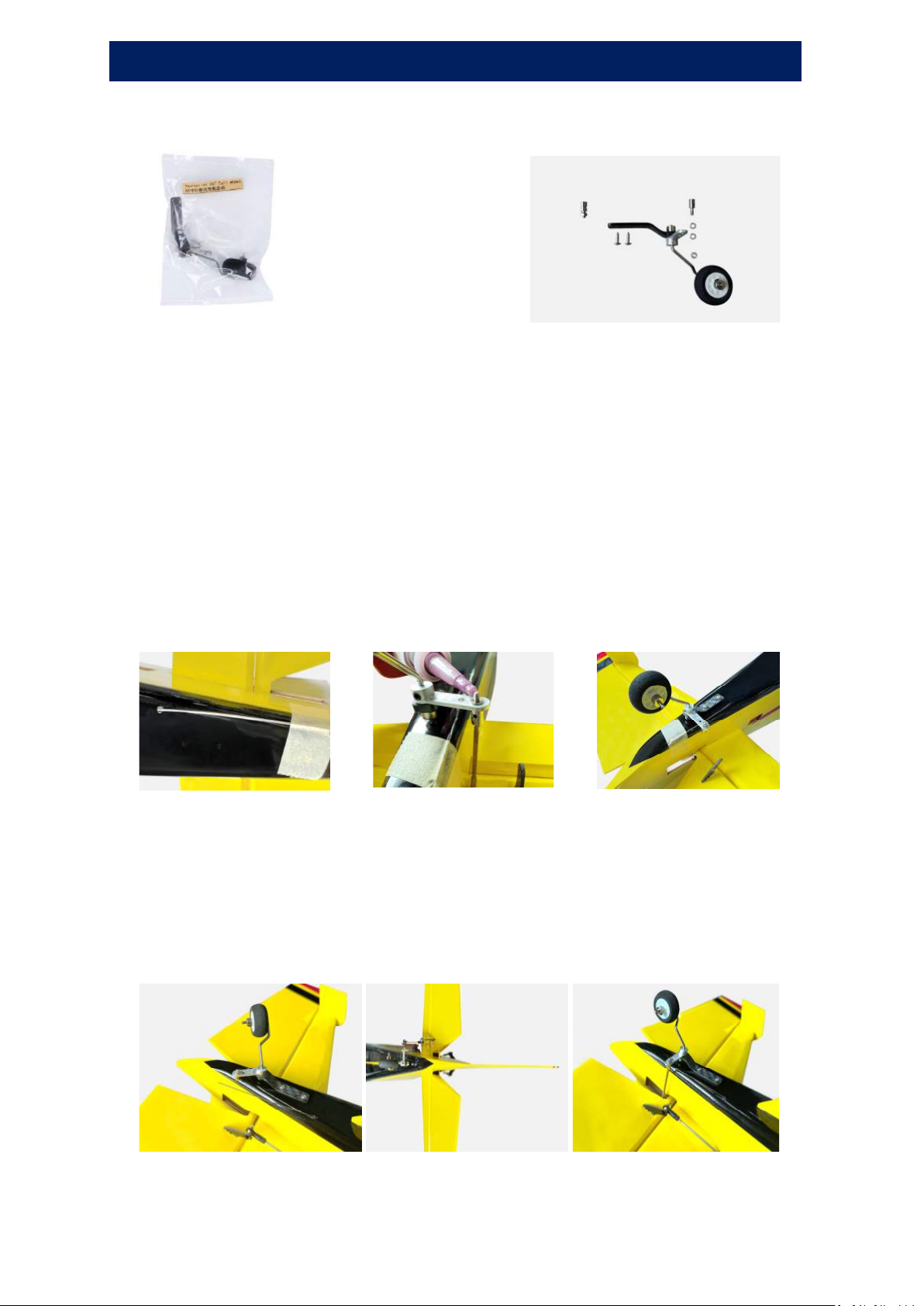
Tail wheel assembly
1. Take out tail wheel landing gear hardware
2. Find the securing holes on the tail wheel installation plate,
use a utility knife make a mark.
3. Put the metal regulator into the aluminum steering part as in
Figure, apply thread locking adhesive-Low Strength to the top
of regulator, then screw on the locknut, take note that do not
screw the lock nut too tight, ensure that it can rotate
smoothly. To have a better effect, can put a little grease into
the gap between regulator and lock nut.
4. Find the tail wheel control steel wire, thread it into the
regulator, ensure the rudder and tail wheel are aligned in a
straight line; use a 1.5mm inner hexagon screwdriver to
tighten the locking screw of the regulator to lock the steel
wire.
Zhuhai Edge Smart Drive Technology Co., Ltd.
www.omphobby.com
Page 15
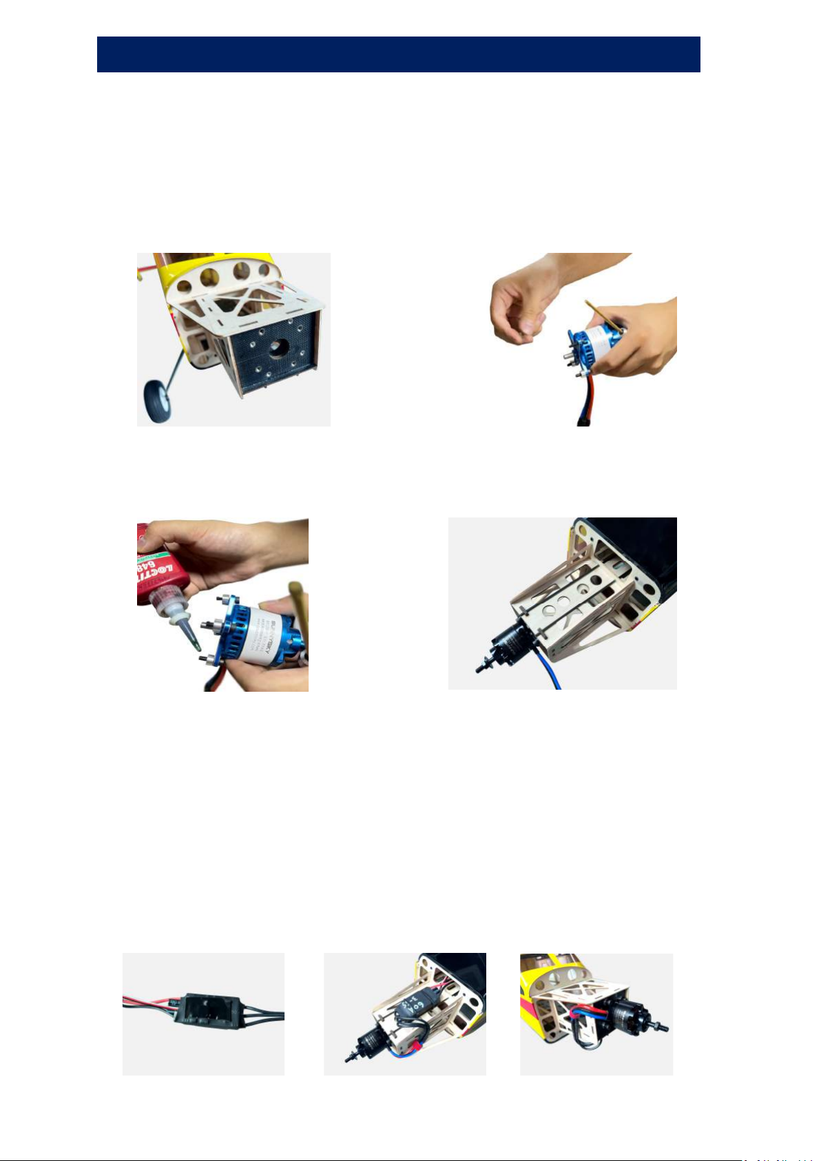
Power Systems assembly
Ø Motor Installation
1. There two types of mounting holes on the head plate of
fuselage, can be selected accroding to motor specifications.
2. Put the screws into motor mounts and put aluminum columns
to the other side of the screws.
3. Apply glue to the screws and install motor to motor holder,
please pay attention that the motor cable should be to the left
or right direction.
Ø ESC Installation
1. Attach the connected ESC to ESC holder with double-sided
tape and Secure with cable ties.
2. Tie the wires of ESC and motor with fastening strap.
Please take note that the battery elimination circuit of ESC could be 5V,
6V, 7.4V ,because some customers’ receiver equipment does not
support high voltage, so the factory default set is 6V, if you receiver
support high voltage (2s,8.4V), then we suggest that you set the bec to
7.4v, so that servo power will be more strong and the speed will be
more fast. The switch is on the back of ESC (no sticker side) .
Zhuhai Edge Smart Drive Technology Co., Ltd.
www.omphobby.com
Page 16
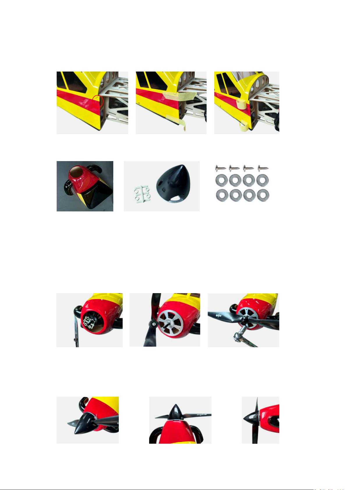
Ø Propeller, Spinner, Cowl Installation
1. Find the four screw fixing holes in the fuselage, stick masking
tapes to mark the holes, tear open the front part of masking
tapes.
2. Take out Cowl, Spinner and cowl hardware
3. Install cowl to fuselage(please take note that motor must be
in the center position),then put the suitable gasket to the
motor, install the aluminum spinner back-plate, propeller
(the side which have words face upward), screw gasket and
propeller spinner adapter in succession.
4. Secure the spinner with screws, please pay attention that
spinner must be located in the centre position of the cowl, and
spinner edge is parallel to the cowl, gap is about 2mm.
Zhuhai Edge Smart Drive Technology Co., Ltd.
www.omphobby.com
Page 17
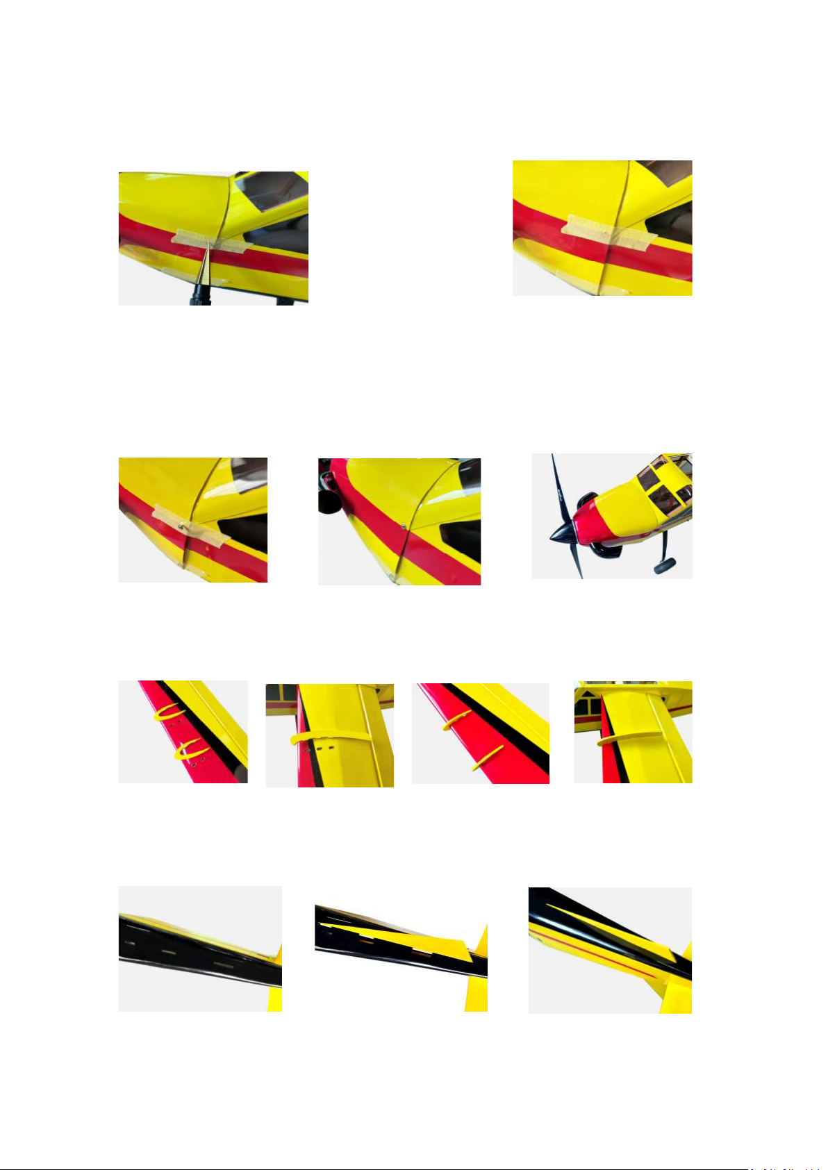
5. After determining the gap, stick the masking tapes to the
canopy, use a drill or a utility knife to bore a hole according to
the marked fixing holes.
6. Use a small size of Phillips screwdriver to tighten the T2x 8mm
self-tapping screws along with washers to the cowl, tear off the
masking tapes when a half part of the screws be twisted into
the cowl, then continue to tighten the screws.
7. Install the wing fences as in Figure, apply glue to fix it
8. Install the ventral fin as in Figure, apply glue to fix it
Zhuhai Edge Smart Drive Technology Co., Ltd.
www.omphobby.com
Page 18
Recommended Settings of Dual Rates and
Exponentials of Control Throws
Low rates(deg) Low rates (exp) High rates(deg) High rates (exp)
Aileron 15 30% 38 45%
Elevator 15 30% 45 45%
Rudder 15 30% 48 50%
For customer support in the USA, please
contact Ohio Model Products in Ohio.
Tel: +1-614-733-9488 (9am -5pm, ET)
Email: [email protected]
Website: www.OhioModelProducts.com
For customer support outside of the USA,
please contact OMPHobby in China.
Email: [email protected]
Website: www.omphobby.com
Disclaimer and Safety
Ø This product is not a toy. It is not recommended for children under age 14.
Ø Fly the airplane by abiding by local laws and rules.
Ø Fly the airplane in a designated location, and always maintain visual contact of the aircra
ft.
Ø Avoid flying directly over unprotected people, moving vehicles, and occupied structures.
Ø Read the safe code of AMA before flight. The guideline can be downloaded from the foll
owing link: www.modelaircraft.org/files/100.pdf
Zhuhai Edge Smart Drive Technology Co., Ltd.
www.omphobby.com
 Loading...