

Page 1
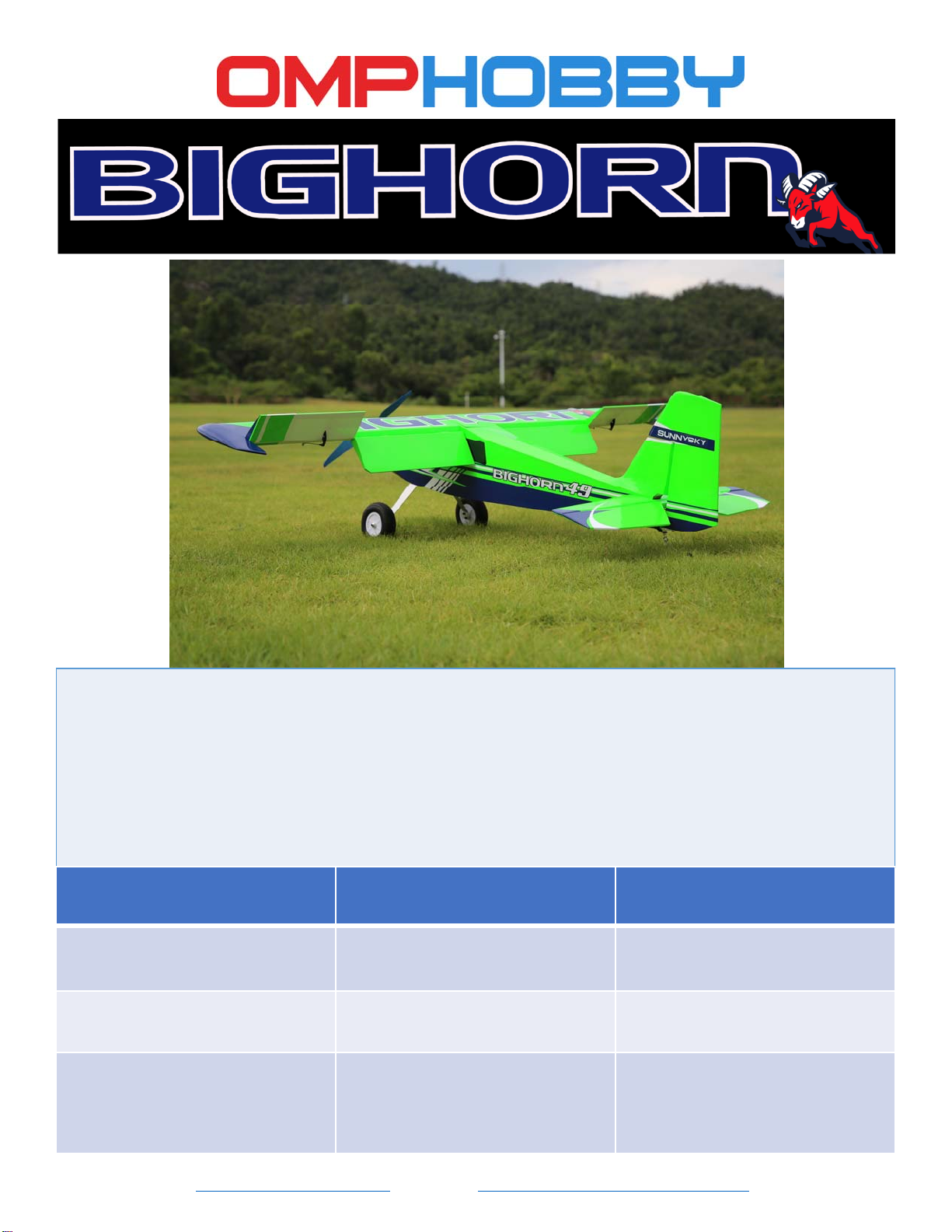
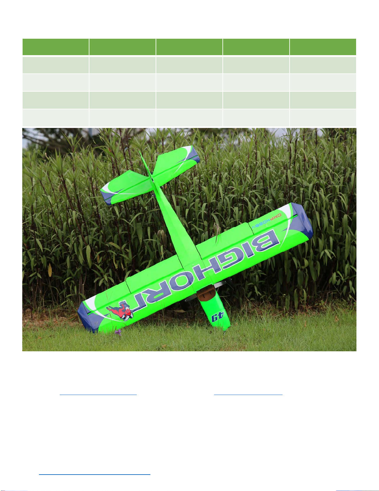
OMP Hobby 49” Bighorn is a sport RC model airplane built in the traditional way: balsa and film cover.
The airplane features light yet strong structure, and abundant power, making the airplane easy to fly and
capable of a lot of advanced aerobatics, such as hover. The big wheels provide enough clearance for easy
takeoff and landing on grass field. Flaps (if equipped) of the airplane makes it ideal for short field takeoff
and landing, and air brake in crow configuration.
The optional 49” Bighorn receiver ready version is an almost completed finished kit in factory. Motor, ESC,
servos, Ailerons, flaps, elevator, are all installed. Landing gear is preassembled. Propeller is included in the
kit. It takes no more than an hour to put the kit together and ready for the sky.
Wingspan
49in(1250mm)
Wing Area: 27.4dm² or 425
square inches
Motor: Sunnysky X2820
1100KV Outrunner
Propeller: SunnySky Eolo
12x6.5” electric propeller
www.OMPHobby.com www.OhioModelProducts.com
Length
41in(1040mm)
Wing Loading: 49.7~51.5g/dm² Flying Weight: 1365~1410g
ESC: 40A
Servos: 6 (flap version) or 4
(non-flap version) of 17g
OMPHOBBY metal gear digital
servos.
CG: 58‐ 66mmfromtheleading
edgeofmainwings
Battery: 3S 11.1V LiPo,
2200~3000mAh
Flight time: 5~12 minutes
1
Page 2
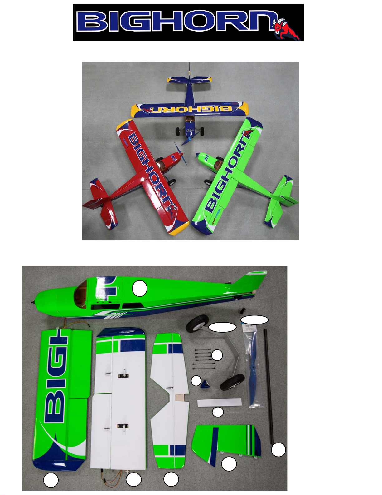
Three color schemes available
Packagecontents(receiverreadyversion)
1
11
10
9
8
7
1. Fuselage
2. Lefthalf wing
3. Righthalfwing
4. Horizontal
stabilizer
5. Rudder
6. Tube
7. Adhesive
Velcro
8. Spinner
9. Link Rods
2
3
4
5
10. Landinggear
6
11. Propeller
2
Page 3
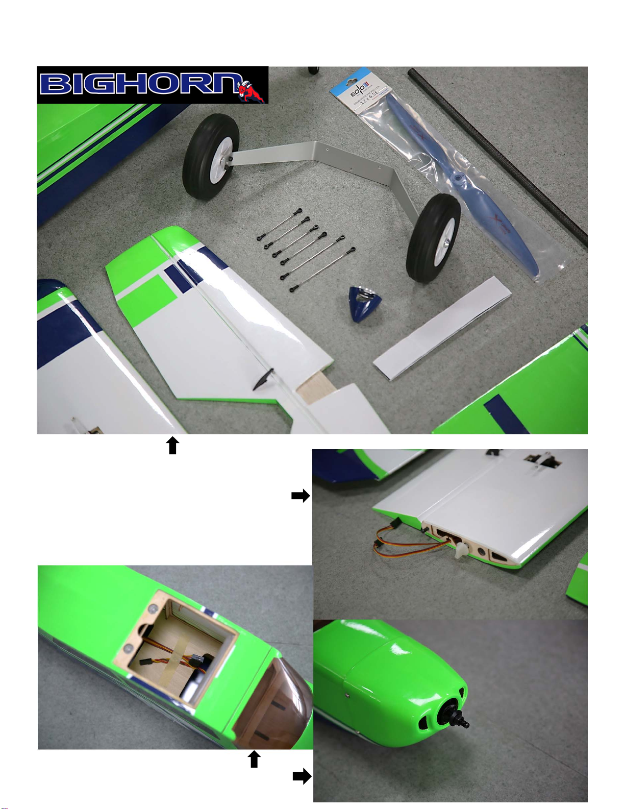
MainFeaturesoftheAirplane(receiverreadyversion)
*Mainlandinggearhasbeenassembledin
factory.
*Allballtierodsarepreassembled.
*Allservohornshavealreadybeeninstalled.
*Allballjointshavebeeninstalled.
*Hingeslotsarecutinfactory.
*Servoleadstapedforeasyaccess.
*Thecowlisinstalledinfactory.
3
Page 4
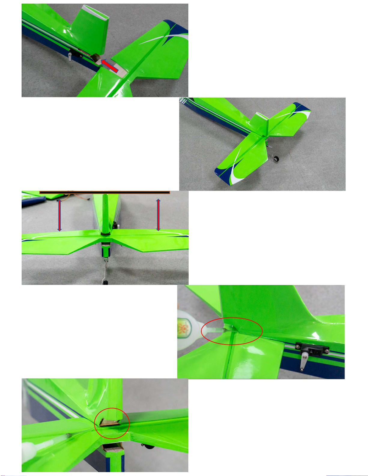
1. Insert the horizontal stabilizer into the
fuselage.
Horizontal stabilizer and
elevator installation
3. Appy CA glue to secure horizontal
stabilizer.
2. Insert the carbon tube of main wings into
fuselage, to ensure that the horizontal
stabilizer is parallel to the carbon tube.
4
Page 5
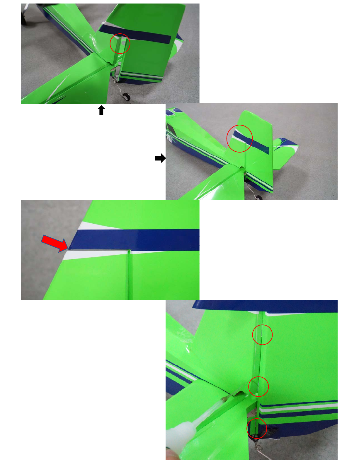
1. Insert rudder hinges into slots in vertical
stabilizer.
Rudder Installation
3. Apply thin CA glue to secure the hinges.
2. Ensure that there is 1 ~ 2mm
clearance between fuselage and rudder.
5
Page 6
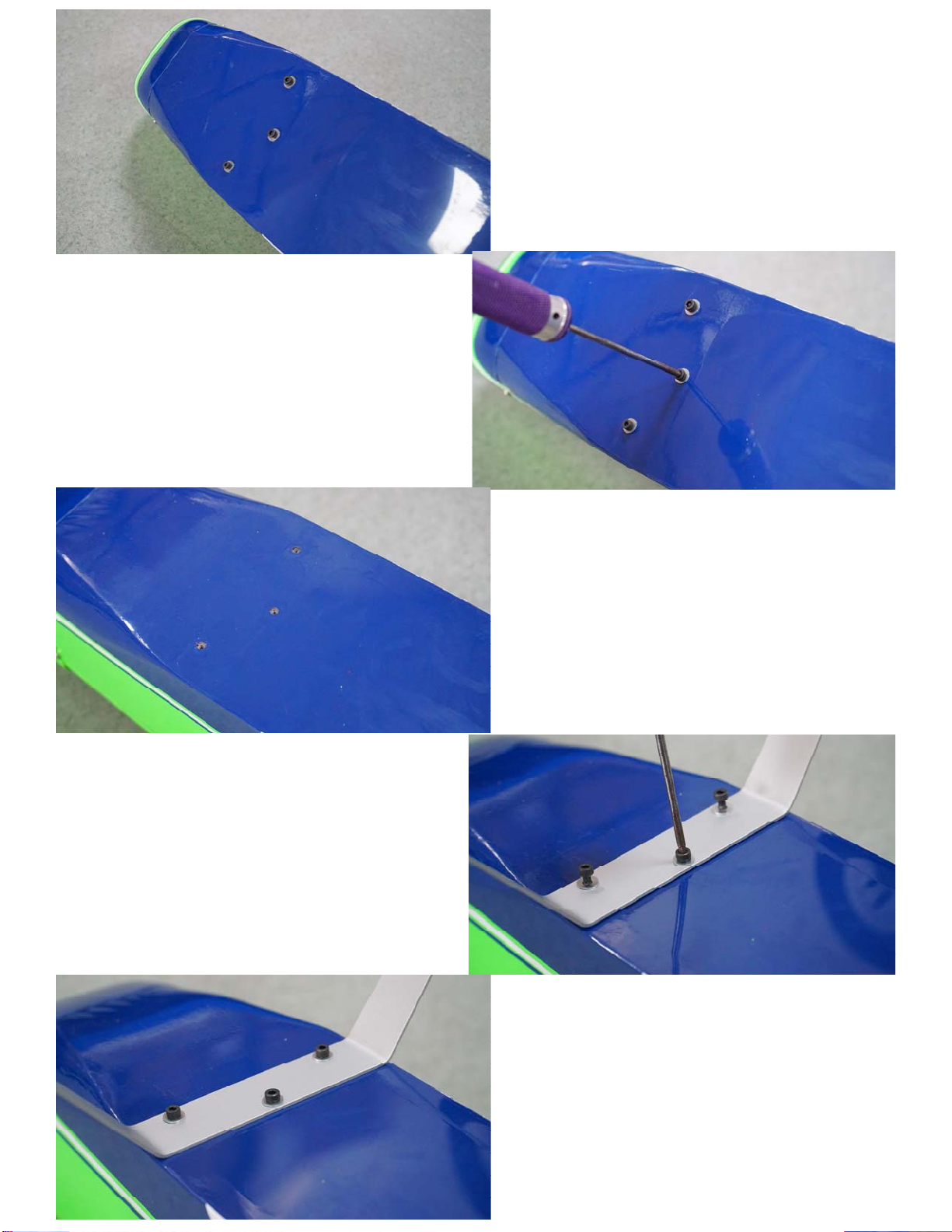
1. The mounting screws of landing gear are
installed on the fuselage to prevent missing
parts.
Landing Gear Installation
3. Align the landing gear to the hole locations
and tighten the three screws. Application of
threadlocker is highly recommended.
2. Take out the screws from the bottom of
fuselage with 2.5mm Alan screwdriver.
6
Page 7
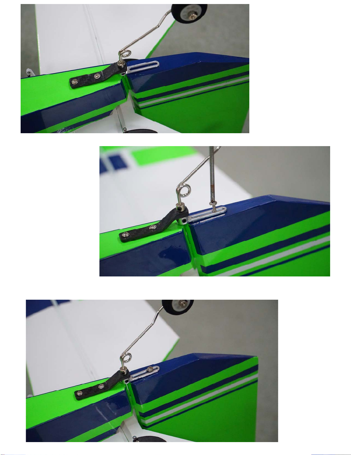
Align tail wheel
assembly to the rear
bottom of fuselage
as shown in the
photos. Make sure
the gear is centered
and pivot is aligned
to rudder hinges.
Install screws at
locations as shown in
the photos.
Installation
of Tail Wheel
7
Page 8
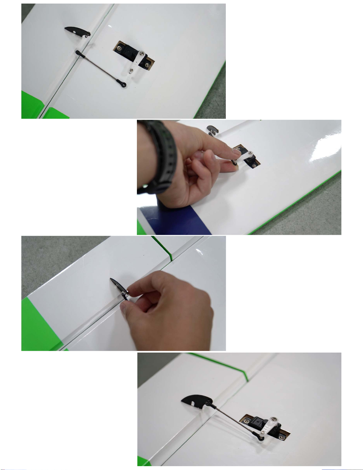
1. Servo horns are installed at
center position in factory.
Hook servos to a receiver to
check center point if
necessary.
2. Level the control surfaces,
and set rudder arms at 90
degree positions.
Installation of
Servo Link Rods
4. Push the ball joint head to
the ball head by using pliers
or hand.
3. Adjust the link rod length by
turning the ball joints to
appropriate positions.
8
Page 9
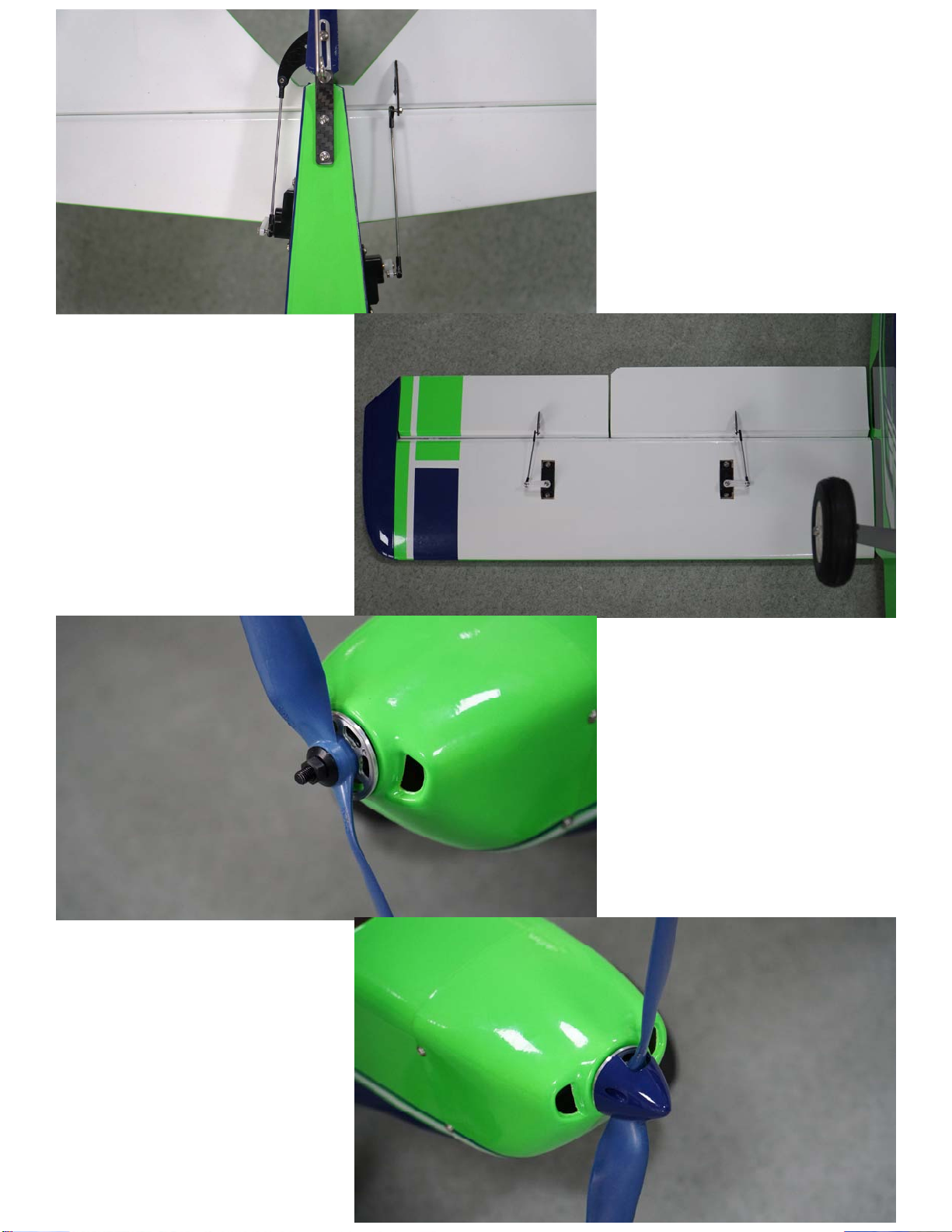
5. Electrify the servos to make
sure all the control surfaces
are installed in the center
positions.
Installation of
Servo Link Rods
(continued)
Installation sequence of spinner
parts:
aluminum alloy base plate →
propeller → washer → nut →
spinner → two screws.
Installation of
Spinner
9
Page 10
Recommended Settings of Dual Rates and
Exponentials of Control Surfaces
Lowrate Lowrateexp Highrate Highrateexp
Ailerons 60 40% 100 40%
Elevator 50 30% 100 30%
Rudder 60 30% 100 30%
Flaps 80 ~ 100 ~
ForcustomersupportintheUSA,please
contactOhioModelProductsinOhio.
Tel: +1‐614‐733‐9488 (9am‐5pm,ET)
Email: [email protected]
Website:www.OhioModelProducts.com
DisclaimerandSafety
• Thisproductisnotatoy.Itisnotrecommendedforchildrenunderage14.
• Fly the airplane by abidingbylocal lawsand rules.
• Flytheairplaneinadesignatedlocation,andalwaysmaintainvisualcontactoftheaircraft.
• Avoidflyingdirectlyoverunprotectedpeople,movingvehicles,andoccupiedstructures.
• ReadthesafecodeofAMAbeforeflight.Theguidelinecanbedownloadedfromthefollowinglink:
www.modelaircraft.org/files/100.pdf
ForcustomersupportoutsideoftheUSA,
pleasecontactOMPHobby inChina.
Tel:+86‐755‐8672‐4337
Email:[email protected]
Website:www.OMPHOBBY.com
10
 Loading...